EP1464900A2 - Refrigeration cycle apparatus and unit for refrigeration cycle apparatus - Google Patents
Refrigeration cycle apparatus and unit for refrigeration cycle apparatus Download PDFInfo
- Publication number
- EP1464900A2 EP1464900A2 EP04007808A EP04007808A EP1464900A2 EP 1464900 A2 EP1464900 A2 EP 1464900A2 EP 04007808 A EP04007808 A EP 04007808A EP 04007808 A EP04007808 A EP 04007808A EP 1464900 A2 EP1464900 A2 EP 1464900A2
- Authority
- EP
- European Patent Office
- Prior art keywords
- expansion device
- rotary shaft
- refrigerant
- compressor
- refrigeration cycle
- Prior art date
- Legal status (The legal status is an assumption and is not a legal conclusion. Google has not performed a legal analysis and makes no representation as to the accuracy of the status listed.)
- Withdrawn
Links
Images

Classifications
-
- F—MECHANICAL ENGINEERING; LIGHTING; HEATING; WEAPONS; BLASTING
- F25—REFRIGERATION OR COOLING; COMBINED HEATING AND REFRIGERATION SYSTEMS; HEAT PUMP SYSTEMS; MANUFACTURE OR STORAGE OF ICE; LIQUEFACTION SOLIDIFICATION OF GASES
- F25B—REFRIGERATION MACHINES, PLANTS OR SYSTEMS; COMBINED HEATING AND REFRIGERATION SYSTEMS; HEAT PUMP SYSTEMS
- F25B9/00—Compression machines, plants or systems, in which the refrigerant is air or other gas of low boiling point
- F25B9/06—Compression machines, plants or systems, in which the refrigerant is air or other gas of low boiling point using expanders
-
- F—MECHANICAL ENGINEERING; LIGHTING; HEATING; WEAPONS; BLASTING
- F04—POSITIVE - DISPLACEMENT MACHINES FOR LIQUIDS; PUMPS FOR LIQUIDS OR ELASTIC FLUIDS
- F04B—POSITIVE-DISPLACEMENT MACHINES FOR LIQUIDS; PUMPS
- F04B27/00—Multi-cylinder pumps specially adapted for elastic fluids and characterised by number or arrangement of cylinders
- F04B27/08—Multi-cylinder pumps specially adapted for elastic fluids and characterised by number or arrangement of cylinders having cylinders coaxial with, or parallel or inclined to, main shaft axis
- F04B27/10—Multi-cylinder pumps specially adapted for elastic fluids and characterised by number or arrangement of cylinders having cylinders coaxial with, or parallel or inclined to, main shaft axis having stationary cylinders
-
- F—MECHANICAL ENGINEERING; LIGHTING; HEATING; WEAPONS; BLASTING
- F04—POSITIVE - DISPLACEMENT MACHINES FOR LIQUIDS; PUMPS FOR LIQUIDS OR ELASTIC FLUIDS
- F04B—POSITIVE-DISPLACEMENT MACHINES FOR LIQUIDS; PUMPS
- F04B35/00—Piston pumps specially adapted for elastic fluids and characterised by the driving means to their working members, or by combination with, or adaptation to, specific driving engines or motors, not otherwise provided for
- F04B35/002—Piston pumps specially adapted for elastic fluids and characterised by the driving means to their working members, or by combination with, or adaptation to, specific driving engines or motors, not otherwise provided for driven by internal combustion engines
-
- F—MECHANICAL ENGINEERING; LIGHTING; HEATING; WEAPONS; BLASTING
- F25—REFRIGERATION OR COOLING; COMBINED HEATING AND REFRIGERATION SYSTEMS; HEAT PUMP SYSTEMS; MANUFACTURE OR STORAGE OF ICE; LIQUEFACTION SOLIDIFICATION OF GASES
- F25B—REFRIGERATION MACHINES, PLANTS OR SYSTEMS; COMBINED HEATING AND REFRIGERATION SYSTEMS; HEAT PUMP SYSTEMS
- F25B9/00—Compression machines, plants or systems, in which the refrigerant is air or other gas of low boiling point
- F25B9/002—Compression machines, plants or systems, in which the refrigerant is air or other gas of low boiling point characterised by the refrigerant
- F25B9/008—Compression machines, plants or systems, in which the refrigerant is air or other gas of low boiling point characterised by the refrigerant the refrigerant being carbon dioxide
-
- F—MECHANICAL ENGINEERING; LIGHTING; HEATING; WEAPONS; BLASTING
- F25—REFRIGERATION OR COOLING; COMBINED HEATING AND REFRIGERATION SYSTEMS; HEAT PUMP SYSTEMS; MANUFACTURE OR STORAGE OF ICE; LIQUEFACTION SOLIDIFICATION OF GASES
- F25B—REFRIGERATION MACHINES, PLANTS OR SYSTEMS; COMBINED HEATING AND REFRIGERATION SYSTEMS; HEAT PUMP SYSTEMS
- F25B1/00—Compression machines, plants or systems with non-reversible cycle
- F25B1/04—Compression machines, plants or systems with non-reversible cycle with compressor of rotary type
-
- F—MECHANICAL ENGINEERING; LIGHTING; HEATING; WEAPONS; BLASTING
- F25—REFRIGERATION OR COOLING; COMBINED HEATING AND REFRIGERATION SYSTEMS; HEAT PUMP SYSTEMS; MANUFACTURE OR STORAGE OF ICE; LIQUEFACTION SOLIDIFICATION OF GASES
- F25B—REFRIGERATION MACHINES, PLANTS OR SYSTEMS; COMBINED HEATING AND REFRIGERATION SYSTEMS; HEAT PUMP SYSTEMS
- F25B2309/00—Gas cycle refrigeration machines
- F25B2309/06—Compression machines, plants or systems characterised by the refrigerant being carbon dioxide
- F25B2309/061—Compression machines, plants or systems characterised by the refrigerant being carbon dioxide with cycle highest pressure above the supercritical pressure
-
- F—MECHANICAL ENGINEERING; LIGHTING; HEATING; WEAPONS; BLASTING
- F25—REFRIGERATION OR COOLING; COMBINED HEATING AND REFRIGERATION SYSTEMS; HEAT PUMP SYSTEMS; MANUFACTURE OR STORAGE OF ICE; LIQUEFACTION SOLIDIFICATION OF GASES
- F25B—REFRIGERATION MACHINES, PLANTS OR SYSTEMS; COMBINED HEATING AND REFRIGERATION SYSTEMS; HEAT PUMP SYSTEMS
- F25B2400/00—Component parts or details not otherwise provided for in this subclass
- F25B2400/07—Details of compressors or related parts
- F25B2400/076—Details of compressors or related parts having multiple cylinders driven by a rotating swash plate
-
- F—MECHANICAL ENGINEERING; LIGHTING; HEATING; WEAPONS; BLASTING
- F25—REFRIGERATION OR COOLING; COMBINED HEATING AND REFRIGERATION SYSTEMS; HEAT PUMP SYSTEMS; MANUFACTURE OR STORAGE OF ICE; LIQUEFACTION SOLIDIFICATION OF GASES
- F25B—REFRIGERATION MACHINES, PLANTS OR SYSTEMS; COMBINED HEATING AND REFRIGERATION SYSTEMS; HEAT PUMP SYSTEMS
- F25B2600/00—Control issues
- F25B2600/02—Compressor control
- F25B2600/025—Compressor control by controlling speed
- F25B2600/0253—Compressor control by controlling speed with variable speed
-
- Y—GENERAL TAGGING OF NEW TECHNOLOGICAL DEVELOPMENTS; GENERAL TAGGING OF CROSS-SECTIONAL TECHNOLOGIES SPANNING OVER SEVERAL SECTIONS OF THE IPC; TECHNICAL SUBJECTS COVERED BY FORMER USPC CROSS-REFERENCE ART COLLECTIONS [XRACs] AND DIGESTS
- Y02—TECHNOLOGIES OR APPLICATIONS FOR MITIGATION OR ADAPTATION AGAINST CLIMATE CHANGE
- Y02B—CLIMATE CHANGE MITIGATION TECHNOLOGIES RELATED TO BUILDINGS, e.g. HOUSING, HOUSE APPLIANCES OR RELATED END-USER APPLICATIONS
- Y02B30/00—Energy efficient heating, ventilation or air conditioning [HVAC]
- Y02B30/70—Efficient control or regulation technologies, e.g. for control of refrigerant flow, motor or heating
Definitions
- the present invention relates to a refrigeration cycle apparatus having a refrigerant circulation passage including a compressor that increases the pressure of refrigerant, a radiator that cools refrigerant the pressure of which has been increased by the compressor, an expansion device that decompresses and expands the refrigerant cooled by the radiator to extract power to drive the compressor, and an evaporator for heating the refrigerant that has been decompressed and expanded by the expansion device.
- the present invention also pertains to a unit for the refrigeration cycle apparatus.
- the refrigeration cycle apparatus includes a refrigerant circulation passage that includes a compressor, a radiator, an expansion device, and an evaporator.
- the expansion device and a decompression valve are located between the outlet of the radiator and the inlet of the evaporator.
- the expansion device is located upstream of the decompression valve.
- the expansion device decompresses and expands refrigerant that has been cooled by the radiator, thereby generating power.
- the expansion device then transmits the power to the compressor. That is, the expansion device recovers power.
- a structure may be employed in which a rotary shaft for transmitting power generated by the expansion device is connected to a rotary shaft for driving the compressor, so that the shafts rotate integrally.
- the flow rate of refrigerant discharged by the expansion device can fluctuate under the influence of rotation speed of the rotary shaft of the compressor.
- the fluctuation influences the cycle pressure of the refrigerant circulation passage.
- the decompression valve for example, may be constructed to adjust the cycle pressure to cancel the influence.
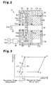
- Line 101 in Fig. 3 represents the relationship between the enthalpy and the pressure of the refrigerant in the above described refrigeration cycle apparatus.
- a condition A represents the enthalpy and the pressure of the refrigerant at the suction inlet of the compressor (that is, at the outlet of the evaporator).
- a condition B represents the enthalpy and the pressure of the refrigerant at the discharge outlet of the compressor (that is, at the inlet of the radiator).
- a condition C represents the enthalpy and the pressure of the refrigerant at the inlet of the expansion device (that is, at the outlet of the radiator).
- a condition D represents the enthalpy and the pressure of the refrigerant at the outlet of the expansion device (that is, at the inlet of the decompression valve).
- a condition E represents the enthalpy and the pressure of the refrigerant at the outlet of the decompression valve (that is, at the inlet of the evaporator).
- the refrigerant shifts from the condition C to the condition D due to decompression and expansion by the expansion device.
- the difference of enthalpy between the condition C and the condition D represents the magnitude of power generated by the expansion device.
- the refrigerant is shifted from the condition D to the condition E of a lower pressure by the decompression valve.
- the decompression valve decreases the pressure of refrigerant by an amount corresponding to the pressure difference between the condition D and the condition E in order to adjust the cycle pressure. Therefore, the amount of power that corresponds to the decompression cannot be recovered
- the present invention provides a refrigeration cycle apparatus.
- the refrigeration cycle apparatus has a compressor, a radiator, an expansion device, an evaporator, and a variable discharge rate mechanism.
- the compressor has a rotary shaft.
- the rotary shaft is rotated by an external drive source.
- the compressor increases the pressure of refrigerant.
- the radiator cools refrigerant the pressure of which has been increased by the compressor.
- the expansion device decompresses and expands refrigerant that has been cooled by the radiator, and then discharges the refrigerant.
- the expansion device generates power using the decompression and expansion and transmits the power to the rotary shaft.
- the evaporator heats refrigerant that has been decompressed and expanded by the expansion device.
- the variable discharge rate mechanism is capable of changing the discharge rate of the expansion device per rotation of the rotary shaft.
- the present invention also provides a unit incorporated in a refrigeration cycle apparatus.
- the refrigeration cycle apparatus includes a radiator for cooling introduced refrigerant, and an evaporator for heating introduced refrigerant.
- the unit has a compressor, an expansion device and a variable discharge rate mechanism.
- the compressor has a rotary shaft. The rotary shaft is rotated by an external drive source. When the rotary shaft is rotated, the compressor increases the pressure of refrigerant and sends the refrigerant to the radiator.
- the expansion device decompresses and expands refrigerant sent from the radiator, and discharges the refrigerant to the evaporator.
- the expansion device generates power using the decompression and expansion and transmits the power to the rotary shaft.
- the variable discharge rate mechanism changes the discharge rate of the expansion device per rotation of the rotary shaft.
- the compressor, the expansion device, and the variable discharge rate mechanism are integrated.
- a vehicular refrigeration cycle apparatus and a unit for the refrigeration cycle apparatus according to first and second embodiments of the present invention will be described in the following.
- the second embodiment only the components different from the first embodiment are explained.
- Like or similar components are given the like numbers and detailed explanations are omitted.
- the refrigeration cycle apparatus has a refrigerant circulation passage, which includes a compressor 11, a radiator 12, an expansion device 13, and an evaporator 14. Carbon dioxide is used as refrigerant (fluid) in the refrigerant circulation passage.
- the refrigerant circulation passage has refrigerant passages 20, 21.
- the refrigerant passage 20 includes a pipe connecting a discharge port 11b of the compressor 11 with an inlet 12a of the radiator 12.
- the refrigerant passage 21 connects an outlet 12b of the radiator 12 with an inlet 13a of the expansion device 13.
- the refrigerant circulation passage also has refrigerant passages 22, 23.
- the refrigerant passage 22 connects an outlet 13b of the expansion device 13 with an inlet 14a of the evaporator 14.
- the refrigerant passage 23 connects an outlet 14b of the evaporator 14 with a suction port 11a of the compressor 11.
- a pressure sensor (detection device) 12c and a temperature sensor 12d are provided at the outlet 12b of the radiator 12.
- the pressure sensor 12c detects the pressure of refrigerant at the outlet 12b, which represents a cycle pressure in this embodiment.
- the temperature sensor 12d detects the temperature of the refrigerant. Detection values of the sensors 12c, 12d are sent to an air conditioner ECU 15 (see Fig. 2).
- the air conditioner ECU 15 functions as a controller.
- the compressor 11 draws refrigerant from the evaporator 14 through the refrigerant passage 23 and the suction port 11a.
- the compressor 11 compresses the drawn refrigerant, or increases the pressure of the refrigerant.
- the compressor 11 then discharges the compressed gas to the refrigerant passage 20 through the discharge port 11b.
- the radiator 12 performs heat exchange between the refrigerant from the refrigerant passage 20 and the outside air, thereby cooling the refrigerant.
- the refrigerant in the radiator 12 is drawn to the expansion device 13 through the refrigerant passage 21.
- the expansion device 13 decompresses and expands the refrigerant, thereby extracting power to be supplied to the compressor 11.
- the expansion device 13 discharges the decompressed and expanded refrigerant to the refrigerant passage 22 through the outlet 13b.
- the evaporator 14 performs heat exchange between the refrigerant from the refrigerant passage 22 and the outside air, thereby heating the refrigerant.
- the compressor 11 will now be described.
- the left end of the compressor 11 in Fig. 1 is defined as the front of the compressor 11, and the right end is defined as the rear of the compressor 11.
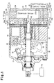
- the housing of the compressor 11 includes a cylinder block 31, a front housing member 32, a cylinder head 34, and a rear housing member 35.
- the front housing member 32 is joined to the front end of the cylinder block 31.
- the cylinder head 34 is joined to the rear end of the cylinder block 31 with a valve assembly 33 in between.
- the rear housing member 35 is joined to the rear end of the cylinder head 34.
- a piston type compression mechanism 36 is accommodated in the housing of the compressor 11.
- the compression mechanism 36 includes a compression mechanism rotary shaft 37 and a swash plate 38.
- the swash plate 38 rotates along rotation of the compression mechanism rotary shaft 37. Pairs of shoes 39 are provided at the peripheral portion of the swash plate 38. Rotation of the swash plate 38 is converted into reciprocation of pistons 40 by the shoes 39.
- Refrigerant is compressed accordingly.
- a suction chamber 41 and a discharge chamber 42 are defined in the cylinder head 34. Refrigerant is drawn to the suction chamber 41 from the refrigerant passage 23 through the suction port 11a. The refrigerant is then drawn to compression chambers 43 and compressed in the compression chambers 43. The compressed gas is discharged to the refrigerant passage 20 through the discharge chamber 42 and the discharge port 11b.
- a front portion of the compression mechanism rotary shaft 37 is rotatably supported by the front housing member 32 and protrudes to the outside of the compressor housing.
- the front portion of the compression mechanism rotary shaft 37 which extends to the outside of the housing, is coupled to and driven by an engine Eg, which is a drive source of the vehicle, by way of a power transmission mechanism (not shown).
- the compression mechanism rotary shaft 37 is rotated by power of the engine Eg. That is, the engine Eg functions as a drive source of the compressor 11.
- a rear portion of the compression mechanism rotary shaft 37 is rotatably supported by the cylinder block 31.
- the rear end of the compression mechanism rotary shaft 37 extends through the valve assembly 33 and projects rearward from the valve assembly 33 to be located in a through hole 34a formed in the center of the cylinder head 34.
- the compression mechanism 36 is of a variable displacement type. That is, the swash plate 38 is housed in a crank chamber 44 and can be inclined with respect to the compression mechanism rotary shaft 37. The pressure in the crank chamber 44 is controlled by adjusting the opening degree of a control valve 45. Accordingly, the stroke of the pistons 40 is changed to vary the compressor displacement.
- the expansion device 13 will now be described.
- the expansion device 13 is accommodated in the rear housing member 35 of the compressor 11.
- the housing of the expansion device 13 is integrated with the housing of the compressor 11.
- the compressor 11 and the expansion device 13 accommodated in the housing of the compressor 11 form a unit for a refrigeration cycle apparatus.
- a circulation hole 21b is formed in the rear housing member 35 to communicate with the inlet 13a of the expansion device 13.
- a pipe 21a is attached to the rear housing member 35 to communicate with the circulation hole 21b.
- the pipe 21a and the circulation hole 21b form the refrigerant passage 21.
- a circulation hole 22b is formed in the rear housing member 35 to communicate with the outlet 13b of the expansion device 13.
- a pipe 22a is attached to the rear housing member 35 to communicate with the circulation hole 22b.
- the pipe 22a and the circulation hole 22b form the refrigerant passage 22.
- the expansion device 13 includes a vane type expansion mechanism 50, and a variable-speed mechanism 51 forming a variable discharge rate mechanism.
- the housing of the expansion device 13 is formed of a front housing member 52 and a rear housing member 54, which is joined to the rear end of the front housing member 52 with a wall plate 53 in between.
- the front housing member 52 and the wall plate 53 serve as the housing of the variable-speed mechanism 51. That is, in this embodiment, the housing of the variable-speed mechanism 51 forms part of the housing of the expansion device 13.
- the expansion mechanism 50 includes a substantially cylindrical rotor 56. Vane grooves are formed in radial directions on the outer circumferential surface of the rotor 56. The expansion mechanism 50 also has vanes each of which received by one of the vane grooves to reciprocate therein.
- a rotor chamber 57 is defined between the wall plate 53 and the rear housing member 54.
- the rotor 56 is fixed to an expansion mechanism rotary shaft 55 to rotate integrally with the expansion mechanism rotary shaft 55.
- the expansion mechanism rotary shaft 55 extends through the rotor chamber 57 and rotatably supported by the wall plate 53 and the rear housing member 54 with bearings.
- a space defined by the inner circumferential surface of the rotor chamber 57, the outer circumferential surface of the rotor 56, and each adjacent pair of the vanes consists a refrigerant chamber 57a to decompress and expand refrigerant. Refrigerant is drawn into each refrigerant chamber 57a through the inlet 13a.
- the refrigerant is then decompressed and expanded, which generates rotational force of the rotor 56.
- the rotational force is extracted as power by way of the expansion mechanism rotary shaft 55.
- the decompressed and expanded refrigerant is discharged to the refrigerant passage 22 from the refrigerant chamber 57a through the outlet 13b.
- variable-speed mechanism chamber 58 is defined between the front housing member 52 and the wall plate 53 to accommodate the variable-speed mechanism 51.
- a through hole 53a is formed in the wall plate 53.
- the expansion mechanism rotary shaft 55 protrudes into the variable-speed mechanism chamber 58 through the through hole 53a.
- the variable-speed mechanism 51 is a planetary gear train.
- An internal gear 60 which is part of the variable-speed mechanism 51, is fixed to the front end portion of the expansion mechanism rotary shaft 55, which protrudes into the variable-speed mechanism chamber 58.
- the internal gear 60 rotates integrally with the expansion mechanism rotary shaft 55.
- a variable-speed mechanism rotary shaft 61 is rotatably supported by the front wall of the front housing member 52 with bearings. A front end portion of the variable-speed mechanism rotary shaft 61 protrudes frontward of the front housing member 52 through a through hole 52a formed in the front wall of the front housing member 52. A sun gear 62 is fixed to the rear end of the variable-speed mechanism rotary shaft 61 to rotate integrally with the shaft 61.
- Three planetary gears 63 are located between and meshed with the internal gear 60 and the sun gear 62.
- a gear carrier 64 is supported on the outer circumferential surface of the variable-speed mechanism rotary shaft 61 to rotate relative to the variable-speed mechanism rotary shaft 61.
- Three support shafts 64b projects from the gear carrier 64.
- Each planetary gear 63 is rotatably supported by the gear carrier 64 with one of the support shafts 64b.
- a main body 64a of the gear carrier 64 is formed as a spur gear.
- a teeth portion 64c of the main body 64a is meshed with a gear (not shown) fixed to an output shaft of an electric motor 65.
- the rotation speed of the gear carrier 64 about the axis of the variable-speed mechanism rotary shaft 61 is adjusted by controlling the electric motor 65, that is by controlling the rotation speed and the rotation direction of the electric motor 65.
- An engagement recess 61a is formed in the front end face of the variable-speed mechanism rotary shaft 61.
- the engagement recess 61a is engaged with an engagement projection 37a formed on the rear end face of the compression mechanism rotary shaft 37 (see Fig. 1).
- the engagement permits power to be transmitted between the compression mechanism rotary shaft 37 and the variable-speed mechanism rotary shaft 61. That is, the variable-speed mechanism 51 is located in the power transmission path between the compression mechanism rotary shaft 37 and the expansion mechanism rotary shaft 55.
- Control of the electric motor 65 permits the variable-speed mechanism 51 to continuously change the ratio of the rotation speed, or the gear ratio, between the compression mechanism rotary shaft 37 and the expansion mechanism rotary shaft 55. Adjusting the rotation speed ratio between the compression mechanism rotary shaft 37 and the expansion mechanism rotary shaft 55 permits the discharge rate of the expansion device 13 per rotation of the compression mechanism rotary shaft 37 to be adjusted.
- the air conditioner ECU 15 controls the electric motor 65 based on a detection value of the pressure sensor 12c and a detection value of the temperature sensor 12d such that the refrigerant pressure at the outlet 12b of the radiator 12 corresponds to the refrigerant temperature, thereby maintaining a coefficient of performance (COP) at a high level. That is, based on a detection value of the temperature sensor 12d, the air conditioner ECU 15 computes a target value of the cycle pressure that maintains the COP at a high level. The air conditioner ECU 15 controls the electric motor 65 to eliminate the difference between the detection value of the pressure sensor 12c and the target value.
- COP coefficient of performance
- This embodiment provides the following advantages.
- the invention may be embodied in the following forms.
- the housing of the compressor 11 and the housing of the expansion device 13 are separate.
- the housing of the expansion device 13 may be omitted, and the rear housing member 35 of the compressor 11 may be used as the housing of the expansion device 13.
- the expansion mechanism 50, the variable-speed mechanism 51, and the compressor 11 are integrated. However, at least one of the expansion mechanism 50 and the variable-speed mechanism 51 may be separate and spaced from the compressor 11.
- a scroll type expansion device may be employed.
- piston type compression mechanism 36 that is capable of changing the displacement is used.
- other types of compression mechanism may be used.
- a piston type compression mechanism of fixed displacement may be employed.
- Compression mechanisms other than piston type for example, a scroll type compression mechanism or a vane type compression mechanism may be employed.
- the present invention may be applied to a refrigeration cycle apparatus that is not used in vehicles.
- Refrigerant other than carbon dioxide may be used.
- chlorofluorocarbon may be used.
- the pressure sensor 12c and the temperature sensor 12d provided at the outlet of the radiator 12 are omitted.
- a pressure sensor (detection means) and a temperature sensor are provided at the outlet 14b of the evaporator 14 to detect the refrigerant pressure (the cycle pressure) and the refrigerant temperature at the outlet 14b.
- the air conditioner ECU computes a target value of the cycle pressure suitable for maintaining the COP at a high level based, for example, on a detection value of the temperature sensor. Then, the air conditioner ECU adjusts the discharge rate of the expansion device 13 by driving the variable discharge rate mechanism in a direction minimizing the difference between the detection value of the pressure sensor and the target value.
Landscapes
- Engineering & Computer Science (AREA)
- Mechanical Engineering (AREA)
- General Engineering & Computer Science (AREA)
- Physics & Mathematics (AREA)
- Thermal Sciences (AREA)
- Chemical & Material Sciences (AREA)
- Combustion & Propulsion (AREA)
- Chemical Kinetics & Catalysis (AREA)
- Control Of Positive-Displacement Pumps (AREA)
- Compressors, Vaccum Pumps And Other Relevant Systems (AREA)
- Air-Conditioning For Vehicles (AREA)
Abstract
Description
Claims (14)
- A refrigeration cycle apparatus, comprising:a compressor having a rotary shaft, wherein the rotary shaft is rotated by an external drive source, wherein, when the rotary shaft is rotated, the compressor increases the pressure of refrigerant;a radiator for cooling refrigerant the pressure of which has been increased by the compressor;an expansion device, wherein the expansion device decompresses and expands refrigerant that has been cooled by the radiator, and then discharges the refrigerant, and wherein the expansion device generates power using the decompression and expansion and transmits the power to the rotary shaft;an evaporator, wherein the evaporator heats refrigerant that has been decompressed and expanded by the expansion device, the apparatus being characterized by:a variable discharge rate mechanism, which is capable of changing the discharge rate of the expansion device per rotation of the rotary shaft.
- The refrigeration cycle apparatus according to claim 1, characterized in that the expansion device has a rotary shaft, wherein the variable discharge rate mechanism is a variable-speed mechanism located between the rotary shaft of the compressor and the rotary shaft of the expansion device, and wherein the variable-speed mechanism changes the ratio of rotation speed between the rotary shaft of the compressor and the rotary shaft of the expansion device.
- The refrigeration cycle apparatus according to claim 2, characterized in that the variable-speed mechanism is a planetary gear train.
- The refrigeration cycle apparatus according to claim 1, characterized in that the variable discharge rate mechanism is a variable displacement mechanism, wherein the variable displacement mechanism is incorporated in the expansion device and is capable of changing the displacement of the expansion device.
- The refrigeration cycle apparatus according to claim 4, characterized in that the variable displacement mechanism includes a piston, a swash plate that converts rotation of the rotary shaft into reciprocation of the piston, and an actuator that changes the inclination angle of the swash plate, and wherein the displacement of the expansion device is changed according to the inclination angle of the swash plate.
- The refrigeration cycle apparatus according to any one of claims 1 to 5, further being characterized by:a refrigerant circulation passage that includes the radiator, the evaporator, the compressor, and the expansion device;a detection device that detects the pressure at an arbitrary section in the refrigerant circulation passage; anda controller that controls the variable discharge rate mechanism such that the difference between a detection value of the detection device and a predetermined target value is eliminated.
- The refrigeration cycle apparatus according to claim 6, characterized in that the detection device detects the pressure at a section of the refrigerant circulation passage in the vicinity of an outlet of the radiator.
- The refrigeration cycle apparatus according to claim 6, characterized in that the controller determines the target value based on the temperature of the refrigerant at an outlet of the radiator.
- The refrigeration cycle apparatus according to any one of claims 1 to 8, characterized in that the refrigerant is carbon dioxide.
- The refrigeration cycle apparatus according to any one of claims 1 to 9, characterized in that the apparatus is mounted on a vehicle, and wherein the external drive source is a drive source of the vehicle.
- The refrigeration cycle apparatus according to any one of claims 1 to 10, characterized in that the compressor, the expansion device, and the variable discharge rate mechanism are integrated.
- The refrigeration cycle apparatus according to claim 11, characterized in that the expansion device and the variable discharge rate mechanism are incorporated in the housing of the compressor.
- A unit forming a part of the refrigeration cycle apparatus according to any one of claims 1 to 10, characterized in that the compressor, the expansion device, and the variable discharge are integrated.
- The unit according to claim 13, characterized in that the expansion device and the variable discharge rate mechanism are incorporated in a housing of the compressor.
Applications Claiming Priority (2)
| Application Number | Priority Date | Filing Date | Title |
|---|---|---|---|
| JP2003097047A JP2004301456A (en) | 2003-03-31 | 2003-03-31 | Refrigerating cycle apparatus and equipment for the same |
| JP2003097047 | 2003-03-31 |
Publications (2)
| Publication Number | Publication Date |
|---|---|
| EP1464900A2 true EP1464900A2 (en) | 2004-10-06 |
| EP1464900A3 EP1464900A3 (en) | 2005-03-23 |
Family
ID=32844657
Family Applications (1)
| Application Number | Title | Priority Date | Filing Date |
|---|---|---|---|
| EP04007808A Withdrawn EP1464900A3 (en) | 2003-03-31 | 2004-03-31 | Refrigeration cycle apparatus and unit for refrigeration cycle apparatus |
Country Status (3)
| Country | Link |
|---|---|
| US (1) | US20040211203A1 (en) |
| EP (1) | EP1464900A3 (en) |
| JP (1) | JP2004301456A (en) |
Cited By (2)
| Publication number | Priority date | Publication date | Assignee | Title |
|---|---|---|---|---|
| EP1946016A4 (en) * | 2005-08-15 | 2015-04-29 | Whitemoss Inc | Integrated compressor/expansion engine |
| CN104617747A (en) * | 2015-01-27 | 2015-05-13 | 爱恒能源科技(上海)有限公司 | Variable speed rotary shaft rear-end electric power recovery method and application thereof |
Families Citing this family (5)
| Publication number | Priority date | Publication date | Assignee | Title |
|---|---|---|---|---|
| KR100581557B1 (en) * | 2004-12-14 | 2006-05-22 | 엘지전자 주식회사 | Back pressure device of swing vane compressor |
| JP2007255327A (en) * | 2006-03-23 | 2007-10-04 | Nippon Soken Inc | Expander control device |
| JP4082434B2 (en) * | 2006-05-18 | 2008-04-30 | ダイキン工業株式会社 | Refrigeration equipment |
| JP5447499B2 (en) * | 2011-12-28 | 2014-03-19 | ダイキン工業株式会社 | Refrigeration equipment |
| JP5742882B2 (en) * | 2013-05-30 | 2015-07-01 | トヨタ自動車株式会社 | Motor lock determination device |
Family Cites Families (9)
| Publication number | Priority date | Publication date | Assignee | Title |
|---|---|---|---|---|
| US5038583A (en) * | 1989-12-18 | 1991-08-13 | Gali Carl E | Gas expansion motor equipped air conditioning/refrigeration system |
| US5947854A (en) * | 1997-05-08 | 1999-09-07 | Worksmart Energy Enterprises, Inc. | Combined variable-speed drive and speed reducer for pumps and fans |
| US6234769B1 (en) * | 1997-07-09 | 2001-05-22 | Denso Corporation | Hybrid type compressor driven by engine and electric motor |
| JP2000046429A (en) * | 1998-07-28 | 2000-02-18 | Aisin Seiki Co Ltd | Refrigeration air conditioner |
| WO2000029793A1 (en) * | 1998-11-18 | 2000-05-25 | FKW HANNOVER Forschungszentrum für Kältetechnik und Wärmepumpen GmbH | Piston compressor |
| JP2000234814A (en) * | 1999-02-17 | 2000-08-29 | Aisin Seiki Co Ltd | Vapor compression refrigeration equipment |
| JP2000241033A (en) * | 1999-02-23 | 2000-09-08 | Aisin Seiki Co Ltd | Vapor compression refrigeration equipment |
| US6321564B1 (en) * | 1999-03-15 | 2001-11-27 | Denso Corporation | Refrigerant cycle system with expansion energy recovery |
| JP2002156163A (en) * | 2000-11-16 | 2002-05-31 | Mitsubishi Heavy Ind Ltd | Air conditioner |
-
2003
- 2003-03-31 JP JP2003097047A patent/JP2004301456A/en active Pending
-
2004
- 2004-03-31 US US10/813,779 patent/US20040211203A1/en not_active Abandoned
- 2004-03-31 EP EP04007808A patent/EP1464900A3/en not_active Withdrawn
Cited By (2)
| Publication number | Priority date | Publication date | Assignee | Title |
|---|---|---|---|---|
| EP1946016A4 (en) * | 2005-08-15 | 2015-04-29 | Whitemoss Inc | Integrated compressor/expansion engine |
| CN104617747A (en) * | 2015-01-27 | 2015-05-13 | 爱恒能源科技(上海)有限公司 | Variable speed rotary shaft rear-end electric power recovery method and application thereof |
Also Published As
| Publication number | Publication date |
|---|---|
| EP1464900A3 (en) | 2005-03-23 |
| US20040211203A1 (en) | 2004-10-28 |
| JP2004301456A (en) | 2004-10-28 |
Similar Documents
| Publication | Publication Date | Title |
|---|---|---|
| US6640562B2 (en) | Air-conditioning system for vehicle and its control method | |
| US6230507B1 (en) | Hybrid compressor and control method | |
| US6565329B2 (en) | Electric type swash plate compressor | |
| EP1081378A2 (en) | Control valve for variable displacement compressor | |
| US6663355B2 (en) | Variable displacement compressor | |
| EP0919721A2 (en) | Thermal overload control of a variable displacement compressor | |
| US6848262B2 (en) | Compressor device and control method for the same | |
| US6672844B2 (en) | Apparatus and method for controlling variable displacement compressor | |
| US20040211203A1 (en) | Refrigeration cycle apparatus and unit for refrigeration cycle apparatus | |
| KR100993765B1 (en) | Capacity control valve of variable displacement compressor | |
| US20020041809A1 (en) | Compressor having seal cooling structure | |
| US20010024616A1 (en) | Variable displacement type compressor with suction control valve | |
| US5704769A (en) | Noise suppressing mechanism in piston-type compressor | |
| US20010046444A1 (en) | Slant plate-type variable displacement compressors with capacity control mechanisms | |
| US5287708A (en) | Car air conditioner with a hydraulically driven refrigerant compressor | |
| US5201189A (en) | Refrigerant compressor with an initial seizure prevention means | |
| US20170211561A1 (en) | Variable displacement swash plate type compressor | |
| US6679077B2 (en) | Piston type variable displacement fluid machine | |
| EP1865274A1 (en) | Vapor-compression refrigeration circuit and automotive air-conditioning system using the refrigeration circuit | |
| KR20090092229A (en) | Tilting plate type compressor | |
| JP2007232343A (en) | Refrigeration circuit and compressor | |
| JP5240535B2 (en) | Variable capacity clutchless compressor | |
| KR101729831B1 (en) | Variable displacement swash plate compressor | |
| JP4825519B2 (en) | Expansion compressor | |
| EP1288496A2 (en) | Piston type variable displacement compressor |
Legal Events
| Date | Code | Title | Description |
|---|---|---|---|
| PUAI | Public reference made under article 153(3) epc to a published international application that has entered the european phase |
Free format text: ORIGINAL CODE: 0009012 |
|
| 17P | Request for examination filed |
Effective date: 20040331 |
|
| AK | Designated contracting states |
Kind code of ref document: A2 Designated state(s): AT BE BG CH CY CZ DE DK EE ES FI FR GB GR HU IE IT LI LU MC NL PL PT RO SE SI SK TR |
|
| AX | Request for extension of the european patent |
Extension state: AL LT LV MK |
|
| PUAL | Search report despatched |
Free format text: ORIGINAL CODE: 0009013 |
|
| AK | Designated contracting states |
Kind code of ref document: A3 Designated state(s): AT BE BG CH CY CZ DE DK EE ES FI FR GB GR HU IE IT LI LU MC NL PL PT RO SE SI SK TR |
|
| AX | Request for extension of the european patent |
Extension state: AL LT LV MK |
|
| STAA | Information on the status of an ep patent application or granted ep patent |
Free format text: STATUS: THE APPLICATION HAS BEEN WITHDRAWN |
|
| 18W | Application withdrawn |
Effective date: 20050407 |