EP1464827A1 - A fuel manifold in thixotropic aluminium for the direct injection of fuel into an internal combustion engine - Google Patents
A fuel manifold in thixotropic aluminium for the direct injection of fuel into an internal combustion engine Download PDFInfo
- Publication number
- EP1464827A1 EP1464827A1 EP04101383A EP04101383A EP1464827A1 EP 1464827 A1 EP1464827 A1 EP 1464827A1 EP 04101383 A EP04101383 A EP 04101383A EP 04101383 A EP04101383 A EP 04101383A EP 1464827 A1 EP1464827 A1 EP 1464827A1
- Authority
- EP
- European Patent Office
- Prior art keywords
- fuel
- fuel manifold
- manifold
- head
- supply duct
- Prior art date
- Legal status (The legal status is an assumption and is not a legal conclusion. Google has not performed a legal analysis and makes no representation as to the accuracy of the status listed.)
- Withdrawn
Links
Images


Classifications
-
- F—MECHANICAL ENGINEERING; LIGHTING; HEATING; WEAPONS; BLASTING
- F02—COMBUSTION ENGINES; HOT-GAS OR COMBUSTION-PRODUCT ENGINE PLANTS
- F02M—SUPPLYING COMBUSTION ENGINES IN GENERAL WITH COMBUSTIBLE MIXTURES OR CONSTITUENTS THEREOF
- F02M35/00—Combustion-air cleaners, air intakes, intake silencers, or induction systems specially adapted for, or arranged on, internal-combustion engines
- F02M35/10—Air intakes; Induction systems
- F02M35/10209—Fluid connections to the air intake system; their arrangement of pipes, valves or the like
- F02M35/10216—Fuel injectors; Fuel pipes or rails; Fuel pumps or pressure regulators
-
- F—MECHANICAL ENGINEERING; LIGHTING; HEATING; WEAPONS; BLASTING
- F02—COMBUSTION ENGINES; HOT-GAS OR COMBUSTION-PRODUCT ENGINE PLANTS
- F02M—SUPPLYING COMBUSTION ENGINES IN GENERAL WITH COMBUSTIBLE MIXTURES OR CONSTITUENTS THEREOF
- F02M35/00—Combustion-air cleaners, air intakes, intake silencers, or induction systems specially adapted for, or arranged on, internal-combustion engines
- F02M35/10—Air intakes; Induction systems
- F02M35/10006—Air intakes; Induction systems characterised by the position of elements of the air intake system in direction of the air intake flow, i.e. between ambient air inlet and supply to the combustion chamber
- F02M35/10078—Connections of intake systems to the engine
- F02M35/10085—Connections of intake systems to the engine having a connecting piece, e.g. a flange, between the engine and the air intake being foreseen with a throttle valve, fuel injector, mixture ducts or the like
-
- F—MECHANICAL ENGINEERING; LIGHTING; HEATING; WEAPONS; BLASTING
- F02—COMBUSTION ENGINES; HOT-GAS OR COMBUSTION-PRODUCT ENGINE PLANTS
- F02M—SUPPLYING COMBUSTION ENGINES IN GENERAL WITH COMBUSTIBLE MIXTURES OR CONSTITUENTS THEREOF
- F02M35/00—Combustion-air cleaners, air intakes, intake silencers, or induction systems specially adapted for, or arranged on, internal-combustion engines
- F02M35/10—Air intakes; Induction systems
- F02M35/10209—Fluid connections to the air intake system; their arrangement of pipes, valves or the like
- F02M35/10222—Exhaust gas recirculation [EGR]; Positive crankcase ventilation [PCV]; Additional air admission, lubricant or fuel vapour admission
-
- F—MECHANICAL ENGINEERING; LIGHTING; HEATING; WEAPONS; BLASTING
- F02—COMBUSTION ENGINES; HOT-GAS OR COMBUSTION-PRODUCT ENGINE PLANTS
- F02M—SUPPLYING COMBUSTION ENGINES IN GENERAL WITH COMBUSTIBLE MIXTURES OR CONSTITUENTS THEREOF
- F02M35/00—Combustion-air cleaners, air intakes, intake silencers, or induction systems specially adapted for, or arranged on, internal-combustion engines
- F02M35/10—Air intakes; Induction systems
- F02M35/10314—Materials for intake systems
- F02M35/10327—Metals; Alloys
-
- F—MECHANICAL ENGINEERING; LIGHTING; HEATING; WEAPONS; BLASTING
- F02—COMBUSTION ENGINES; HOT-GAS OR COMBUSTION-PRODUCT ENGINE PLANTS
- F02M—SUPPLYING COMBUSTION ENGINES IN GENERAL WITH COMBUSTIBLE MIXTURES OR CONSTITUENTS THEREOF
- F02M35/00—Combustion-air cleaners, air intakes, intake silencers, or induction systems specially adapted for, or arranged on, internal-combustion engines
- F02M35/10—Air intakes; Induction systems
- F02M35/1034—Manufacturing and assembling intake systems
- F02M35/10347—Moulding, casting or the like
-
- F—MECHANICAL ENGINEERING; LIGHTING; HEATING; WEAPONS; BLASTING
- F02—COMBUSTION ENGINES; HOT-GAS OR COMBUSTION-PRODUCT ENGINE PLANTS
- F02M—SUPPLYING COMBUSTION ENGINES IN GENERAL WITH COMBUSTIBLE MIXTURES OR CONSTITUENTS THEREOF
- F02M55/00—Fuel-injection apparatus characterised by their fuel conduits or their venting means; Arrangements of conduits between fuel tank and pump F02M37/00
- F02M55/02—Conduits between injection pumps and injectors, e.g. conduits between pump and common-rail or conduits between common-rail and injectors
- F02M55/025—Common rails
-
- F—MECHANICAL ENGINEERING; LIGHTING; HEATING; WEAPONS; BLASTING
- F02—COMBUSTION ENGINES; HOT-GAS OR COMBUSTION-PRODUCT ENGINE PLANTS
- F02M—SUPPLYING COMBUSTION ENGINES IN GENERAL WITH COMBUSTIBLE MIXTURES OR CONSTITUENTS THEREOF
- F02M69/00—Low-pressure fuel-injection apparatus ; Apparatus with both continuous and intermittent injection; Apparatus injecting different types of fuel
- F02M69/46—Details, component parts or accessories not provided for in, or of interest apart from, the apparatus covered by groups F02M69/02 - F02M69/44
- F02M69/462—Arrangement of fuel conduits, e.g. with valves for maintaining pressure in the pipes after the engine being shut-down
- F02M69/465—Arrangement of fuel conduits, e.g. with valves for maintaining pressure in the pipes after the engine being shut-down of fuel rails
-
- F—MECHANICAL ENGINEERING; LIGHTING; HEATING; WEAPONS; BLASTING
- F02—COMBUSTION ENGINES; HOT-GAS OR COMBUSTION-PRODUCT ENGINE PLANTS
- F02M—SUPPLYING COMBUSTION ENGINES IN GENERAL WITH COMBUSTIBLE MIXTURES OR CONSTITUENTS THEREOF
- F02M35/00—Combustion-air cleaners, air intakes, intake silencers, or induction systems specially adapted for, or arranged on, internal-combustion engines
- F02M35/10—Air intakes; Induction systems
- F02M35/10006—Air intakes; Induction systems characterised by the position of elements of the air intake system in direction of the air intake flow, i.e. between ambient air inlet and supply to the combustion chamber
- F02M35/10078—Connections of intake systems to the engine
Definitions
- the present invention relates to a fuel manifold for the direct injection of fuel into an internal combustion engine.
- the present invention can be used particularly advantageously for the production of a fuel manifold for the direct injection of petrol into a petrol-driven internal combustion engine to which the following description will explicitly refer without going into detail.
- the petrol manifolds are currently made from plastic material (typically moulded technopolymers) and are secured to the intake manifold, which is also generally made from plastic material, by means of a series of screws.
- Plastic material is easy to process and extremely economic, but does not have good mechanical properties and is not therefore able to bear the relatively high pressures of the petrol used in direct petrol injection with the necessary safety margins.
- the object of the present invention is to provide a fuel manifold for the direct injection of fuel into an internal combustion engine which is free from the drawbacks described above and is easy and economic to embody.
- the present invention therefore relates to a fuel manifold for the direct injection of fuel into an internal combustion engine as set out in claim 1 and, preferably, any one of the subsequent claims dependent directly or indirectly on claim 1.
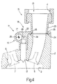
- an internal combustion engine is shown overall by 1 and comprises a head 2 in which four cylinders 3 are provided (only one of which is shown in Fig. 1), each of these cylinders 3 being connected to an intake manifold 4 by means of at least one respective intake valve 5 and to an exhaust manifold 6 by means of a respective exhaust valve 7.
- the intake manifold 4 receives fresh air (i.e. ambient air from outside) by means of a butterfly valve 8 which can be adjusted between a closed position and a position of maximum opening; an exhaust duct 9 provided with one or more catalysts (not shown in detail) leads from the exhaust manifold 6 for the emission into the atmosphere of the gases generated by combustion in the cylinders 3.
- a low pressure pump (not shown in detail) supplies the petrol from a tank (not shown in detail) to a high pressure pump 10 which in turn supplies the petrol to a petrol manifold 11; a series of injectors 12 (one for each cylinder 3) is connected to the petrol manifold 11, each of these injectors 12 being actuated cyclically to inject part of the petrol under pressure in the petrol manifold 11 into the respective cylinder 3.
- the pressure value of the petrol in the petrol manifold 11 is maintained instant by instant at a desired value by means of a pressure regulator 13 which is coupled to the petrol manifold 11 and is adapted to discharge any surplus petrol to a recycling duct which returns this surplus petrol upstream of the low pressure pump (not shown).
- a sensor 14, adapted to measure the pressure value of the petrol in the petrol manifold 11, is also connected to the petrol manifold 11.
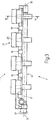
- the fuel manifold 11 is formed by a single monolithic body 15 which is made from thixotropic aluminium by means of a pressure die casting process and comprises a supply duct 16, which is of substantially cylindrical shape, has a central axis of symmetry 17 and is adapted to distribute the petrol under pressure to the injectors 12, and a flange 18 disposed laterally to the supply duct 16.
- the flange 18 has a plurality of through holes 19 so that it can be secured by respective screws 20 to the head 2 of the engine 1 and comprises four coupling members 21, each of which is adapted to bring a respective cylinder 3 into communication with the intake manifold 4.
- the flange 18 comprises a substantially plane plate 22 which extends laterally to the supply duct 16 from a median portion of this supply duct 16; each coupling member 21 comprises a tubular body 23 which rises from the plate 22 in a perpendicular manner with respect to the plane in which the plate 22 lies.
- the end upper portion of each tubular body 23 is shaped to facilitate connection with a respective duct coming from the intake manifold 4.
- a lower surface 24 of the plate 22, i.e. the opposite surface with respect to the tubular bodies 23, is plane and has a relatively very small surface roughness so that it can be coupled in a leak-tight manner (possibly with the interposition of a gasket) with a corresponding upper surface 25 of the head 2.
- a series of reinforcing ribs 26, involving both the plate 22 and the supply duct 16, are provided and are disposed perpendicularly with respect to the plane in which the plate 22 lies and with respect to the axis 17 of the supply duct 16.
- the flange 18 has a series of raised zones 27, via each of which a respective through hole 19 is provided for the passage of a connection screw 20 with the head 2 of the engine 1.
- Part of the reinforcing ribs 26 starts from the raised zones 27, while the remaining part of the reinforcing ribs 26 starts from the tubular bodies 23.
- the supply duct 16 is formed by a main cylindrical tubular channel 28 from which a series of further secondary cylindrical tubular channels 29, disposed perpendicularly with respect to the main cylindrical tubular channel 28, leads; each secondary cylindrical tubular channel 29 is adapted to house a respective injector 12 in a leak-tight manner.
- the main cylindrical tubular channel 28 has two opposite open ends 30 and 31, the end 30 being connected to the high pressure pump 10 in order to supply the petrol under pressure to the petrol manifold 11, while the end 31 is closed by a relative screw cap 32.
- the function of the end 31 is to enable the correct production of the main cylindrical tubular channel 28 during the pressure die casting process for the monolithic body 15.
- the main cylindrical tubular channel 28 has an opening 33 adapted to receive the pressure regulator 13 and an opening 34 adapted to receive the pressure sensor 14.
- the openings 33 and 34 are not formed during the pressure die casting process for the monolithic body 15, but are produced subsequently by drilling of the monolithic body 15.
Landscapes
- Engineering & Computer Science (AREA)
- Chemical & Material Sciences (AREA)
- Combustion & Propulsion (AREA)
- Mechanical Engineering (AREA)
- General Engineering & Computer Science (AREA)
- Manufacturing & Machinery (AREA)
- Fuel-Injection Apparatus (AREA)
- Cylinder Crankcases Of Internal Combustion Engines (AREA)
Abstract
Description
Claims (10)
- A fuel manifold (11) for the direct injection of fuel into an internal combustion engine (1) comprising a head (2) provided with a number of cylinders (3), a number of injectors (12), each of which is connected to the fuel manifold (11) and is adapted directly to inject the fuel into a respective cylinder (3), and an intake manifold (4) which is connected to the head (2) in order to supply fresh air to the cylinders (3), the fuel manifold (11) being characterised in that it is formed by a single monolithic body (15) which is made from thixotropic aluminium by means of a pressure die casting process and comprises a supply duct (16) adapted to distribute the fuel under pressure to the injectors (12), and a flange (18) disposed laterally to the supply duct (16), the flange (18) having a plurality of through holes (19) in order to be secured by respective screws (20) to the head (2) of the engine (1) and comprising a number of coupling members (21), each of which is adapted to bring a respective cylinder (3) into communication with the intake manifold (4).
- A fuel manifold (11) as claimed in claim 1, in which the flange (18) comprises a substantially plane plate (22) which extends laterally to the supply duct (16) from a median portion of this supply duct (16), each coupling member (21) comprising a tubular body which rises from the plate (22) perpendicularly with respect to the plane in which this plate (22) lies.
- A fuel manifold (11) as claimed in claim 2, in which a lower surface (24) of the plate (22) is plane and has a relatively very small surface roughness so that is can be coupled in a leak-tight manner with a corresponding upper surface (25) of the head (2).
- A fuel manifold (11) as claimed in claim 2 or 3, in which a series of reinforcing ribs (26) are provided and are disposed perpendicularly with respect to the plane in which the plate (22) lies and involve both the plate (22) and the supply duct (16).
- A fuel manifold (11) as claimed in claim 4, in which the flange (18) has a series of raised zones (27), via each of which a respective through hole (19) is provided for the passage of a screw (20) for connection to the head (2) of the engine (1).
- A fuel manifold (11) as claimed in claim 5, in which some reinforcing ribs (26) start from the raised zones (27).
- A fuel manifold (11) as claimed in claim 4, 5 or 6, in which some reinforcing ribs (26) start from the tubular bodies (23).
- A fuel manifold (11) as claimed in one of claims 1 to 7, in which the supply duct (16) is formed by a main cylindrical tubular channel (28) from which a series of further secondary cylindrical tubular channels (29), disposed perpendicularly with respect to the main cylindrical tubular duct (28), lead, each secondary cylindrical tubular channel (29) being adapted to house a respective injector (12) in a leak-tight manner.
- A fuel manifold (11) as claimed in claim 8, in which the main cylindrical tubular channel (28) has two opposite open ends (30, 31), one of which is used to supply the fuel under pressure and the other is closed by a relative screw cap (32).
- A fuel manifold (11) as claimed in claim 9, in which, in the vicinity of the end (31) closed by the screw cap (32), the main cylindrical tubular channel (28) has a first opening (33) adapted to receive a pressure regulator (13) and a second opening (34) adapted to receive a pressure sensor (14).
Applications Claiming Priority (2)
| Application Number | Priority Date | Filing Date | Title |
|---|---|---|---|
| ITBO20030200 | 2003-04-04 | ||
| IT000200A ITBO20030200A1 (en) | 2003-04-04 | 2003-04-04 | THIXOTROPIC ALUMINUM FUEL MANIFOLD FOR INJECTION |
Publications (1)
| Publication Number | Publication Date |
|---|---|
| EP1464827A1 true EP1464827A1 (en) | 2004-10-06 |
Family
ID=32843885
Family Applications (1)
| Application Number | Title | Priority Date | Filing Date |
|---|---|---|---|
| EP04101383A Withdrawn EP1464827A1 (en) | 2003-04-04 | 2004-04-02 | A fuel manifold in thixotropic aluminium for the direct injection of fuel into an internal combustion engine |
Country Status (4)
| Country | Link |
|---|---|
| US (1) | US7213575B2 (en) |
| EP (1) | EP1464827A1 (en) |
| BR (1) | BRPI0401562B1 (en) |
| IT (1) | ITBO20030200A1 (en) |
Cited By (1)
| Publication number | Priority date | Publication date | Assignee | Title |
|---|---|---|---|---|
| EP1568880A3 (en) * | 2004-02-27 | 2006-04-19 | Magneti Marelli Powertrain S.p.A. | Dual material fuel manifold for an internal combustion engine with direct fuel injection and method for its production |
Families Citing this family (1)
| Publication number | Priority date | Publication date | Assignee | Title |
|---|---|---|---|---|
| DE60319968T2 (en) * | 2003-06-20 | 2009-04-16 | Delphi Technologies, Inc., Troy | Fuel system |
Citations (4)
| Publication number | Priority date | Publication date | Assignee | Title |
|---|---|---|---|---|
| DE4224908A1 (en) * | 1991-07-31 | 1993-02-04 | Weber Srl | Fuel and air supply device for I.C. engine - consists of two parts, forming air collector, each with seats for injector |
| US5630466A (en) * | 1994-01-17 | 1997-05-20 | Aluminium Pechiney | Process for shaping metal materials in a semi-solid state |
| DE19920195A1 (en) * | 1999-05-03 | 2000-11-16 | Audi Ag | Inlet manifold for injection IC engine has an intermediate manifold with integral mounting for the injectors and with outer ports onto which is fitted the inlet manifold |
| US20030015170A1 (en) * | 2001-06-27 | 2003-01-23 | Filterwerk Mann & Hummel Gmbh | Intermediate flange system for an internal combustion engine with direct fuel injection |
Family Cites Families (10)
| Publication number | Priority date | Publication date | Assignee | Title |
|---|---|---|---|---|
| US4966120A (en) * | 1987-07-29 | 1990-10-30 | Aisan Kogyo Kabushiki Kaisha | Fuel injection system assembly |
| JPH02107758U (en) * | 1989-02-14 | 1990-08-28 | ||
| US5682859A (en) * | 1996-01-22 | 1997-11-04 | Siemens Automotive Corporation | Method and arrangement for mounting fuel rails |
| AU756027B2 (en) * | 1997-10-20 | 2003-01-02 | Chipless Metals Llc. | Making precision castings using thixotropic materials |
| US6427755B1 (en) * | 1997-10-20 | 2002-08-06 | Chipless Metals Llc | Method of making precision casting using thixotropic materials |
| US6338333B1 (en) * | 1999-06-10 | 2002-01-15 | Delphi Technologies, Inc. | Integrated fuel delivery module for direct injection |
| US6405711B1 (en) * | 2000-07-27 | 2002-06-18 | Delphi Technologies, Inc. | Fuel delivery module for fuel injected internal combustion engines |
| US6742489B2 (en) * | 2001-09-19 | 2004-06-01 | Filterwerk Mann & Hummel Gmbh | Intake manifold for internal combustion engine with integrated fuel rail |
| DE10334913B4 (en) * | 2002-08-07 | 2014-03-13 | Siemens Vdo Automotive Inc. | Intake manifold with integrated features |
| ITBO20040114A1 (en) * | 2004-02-27 | 2004-05-27 | Magneti Marelli Powertrain Spa | BI-MATERIAL FUEL MANIFOLD FOR AN INTERNAL COMBUSTION ENGINE WITH DIRECT FUEL INJECTION AND METHOD FOR ITS REALIZATION |
-
2003
- 2003-04-04 IT IT000200A patent/ITBO20030200A1/en unknown
-
2004
- 2004-04-02 US US10/817,221 patent/US7213575B2/en not_active Expired - Fee Related
- 2004-04-02 EP EP04101383A patent/EP1464827A1/en not_active Withdrawn
- 2004-04-05 BR BRPI0401562-2B1A patent/BRPI0401562B1/en not_active IP Right Cessation
Patent Citations (4)
| Publication number | Priority date | Publication date | Assignee | Title |
|---|---|---|---|---|
| DE4224908A1 (en) * | 1991-07-31 | 1993-02-04 | Weber Srl | Fuel and air supply device for I.C. engine - consists of two parts, forming air collector, each with seats for injector |
| US5630466A (en) * | 1994-01-17 | 1997-05-20 | Aluminium Pechiney | Process for shaping metal materials in a semi-solid state |
| DE19920195A1 (en) * | 1999-05-03 | 2000-11-16 | Audi Ag | Inlet manifold for injection IC engine has an intermediate manifold with integral mounting for the injectors and with outer ports onto which is fitted the inlet manifold |
| US20030015170A1 (en) * | 2001-06-27 | 2003-01-23 | Filterwerk Mann & Hummel Gmbh | Intermediate flange system for an internal combustion engine with direct fuel injection |
Non-Patent Citations (1)
| Title |
|---|
| KIUCHI M., KOPP R.: "Mushy / Semi-solid metal forming technology - Present and future", CIRP ANNALS 2002 - KEYNOTE PAPERS, vol. 51, no. 2/2002, 22 October 2002 (2002-10-22), pages 1 - 19, XP002261139, Retrieved from the Internet <URL:http://www.bibl.liu.se/etj2/cirp/2002/2002%5F2/papers/Keynote_STC_F_2002_Mushy.pdf> [retrieved on 20031112] * |
Cited By (1)
| Publication number | Priority date | Publication date | Assignee | Title |
|---|---|---|---|---|
| EP1568880A3 (en) * | 2004-02-27 | 2006-04-19 | Magneti Marelli Powertrain S.p.A. | Dual material fuel manifold for an internal combustion engine with direct fuel injection and method for its production |
Also Published As
| Publication number | Publication date |
|---|---|
| BRPI0401562B1 (en) | 2013-12-17 |
| BRPI0401562A (en) | 2005-01-18 |
| US20050056256A1 (en) | 2005-03-17 |
| US7213575B2 (en) | 2007-05-08 |
| ITBO20030200A1 (en) | 2004-10-05 |
Similar Documents
| Publication | Publication Date | Title |
|---|---|---|
| RU2696185C2 (en) | Diesel engine fuel injector anchor clamp (embodiments) and engine assembly comprising fuel injector clamp | |
| EP1571319A3 (en) | Fuel supply apparatus for internal combustion engine | |
| EP1363001A3 (en) | Air and fuel supply system for combustion engine | |
| US20080196691A1 (en) | Direct Injection Internal Combustion Engine and Injector Used for Direct Injection Internal Combustion Engine | |
| CA2426960A1 (en) | Self-igniting, mixture-compressing internal combustion engine and method for its operation | |
| EP0876553B1 (en) | Method and arrangement for mounting fuel rails | |
| EP1555417A3 (en) | Injection controller for internal combustion engine | |
| JPH10288081A (en) | Cooling structure around fuel injection valve in in-cylinder fuel injection engine | |
| JP2000504078A (en) | Fuel injector fixture for molded intake manifold with integral fuel rail | |
| US20050188956A1 (en) | Dual Material Fuel Manifold For An Internal Combustion Engine With Direct Fuel Injection And Method For Its Production | |
| US7213575B2 (en) | Fuel manifold in thixotropic aluminum for the direct injection of fuel into an internal combustion engine | |
| US8096277B2 (en) | Intake manifold for an internal combustion engine provided with metallic reinforcement brackets for fastening the fuel common rail | |
| US20190331061A1 (en) | Intake manifold with integrated water injection nozzle | |
| US20050166898A1 (en) | Fuel injection system and cylinder head with a central fuel reservoir | |
| EP1321664A3 (en) | Fuel injection system with an apparatus for removing air from fuel | |
| JPH03121263A (en) | Fuel supply device for air-fuel injection type two-cycle engine | |
| JP5262645B2 (en) | Engine fuel supply system | |
| AU2003270170A1 (en) | Cylinder head for a water-cooled internal combustion piston engine having inner reinforcement | |
| US5601062A (en) | Intake system for engine | |
| EP1760304A1 (en) | Integrated air-fuel manifold for an internal combustion engine, and relative production method | |
| EP1691057A3 (en) | Engine of spark ignition type | |
| EP1074730A3 (en) | Center feed of air for assist fuel injector | |
| JPH0680825U (en) | Engine intake system using gas fuel | |
| JPH07243359A (en) | Fuel injector | |
| JPH0323362A (en) | Fuel injection device for internal combustion engine |
Legal Events
| Date | Code | Title | Description |
|---|---|---|---|
| PUAI | Public reference made under article 153(3) epc to a published international application that has entered the european phase |
Free format text: ORIGINAL CODE: 0009012 |
|
| AK | Designated contracting states |
Kind code of ref document: A1 Designated state(s): AT BE BG CH CY CZ DE DK EE ES FI FR GB GR HU IE IT LI LU MC NL PL PT RO SE SI SK TR |
|
| AX | Request for extension of the european patent |
Extension state: AL HR LT LV MK |
|
| 17P | Request for examination filed |
Effective date: 20050401 |
|
| AKX | Designation fees paid |
Designated state(s): DE ES FR GB SE |
|
| 17Q | First examination report despatched |
Effective date: 20061102 |
|
| STAA | Information on the status of an ep patent application or granted ep patent |
Free format text: STATUS: THE APPLICATION IS DEEMED TO BE WITHDRAWN |
|
| 18D | Application deemed to be withdrawn |
Effective date: 20080311 |