EP1464815A1 - Control apparatus and method for internal combustion engine - Google Patents
Control apparatus and method for internal combustion engine Download PDFInfo
- Publication number
- EP1464815A1 EP1464815A1 EP04007119A EP04007119A EP1464815A1 EP 1464815 A1 EP1464815 A1 EP 1464815A1 EP 04007119 A EP04007119 A EP 04007119A EP 04007119 A EP04007119 A EP 04007119A EP 1464815 A1 EP1464815 A1 EP 1464815A1
- Authority
- EP
- European Patent Office
- Prior art keywords
- regeneration
- malfunction
- engine
- parameter value
- amount
- Prior art date
- Legal status (The legal status is an assumption and is not a legal conclusion. Google has not performed a legal analysis and makes no representation as to the accuracy of the status listed.)
- Granted
Links
Images



Classifications
-
- F—MECHANICAL ENGINEERING; LIGHTING; HEATING; WEAPONS; BLASTING
- F02—COMBUSTION ENGINES; HOT-GAS OR COMBUSTION-PRODUCT ENGINE PLANTS
- F02D—CONTROLLING COMBUSTION ENGINES
- F02D41/00—Electrical control of supply of combustible mixture or its constituents
- F02D41/02—Circuit arrangements for generating control signals
- F02D41/14—Introducing closed-loop corrections
- F02D41/1438—Introducing closed-loop corrections using means for determining characteristics of the combustion gases; Sensors therefor
- F02D41/1444—Introducing closed-loop corrections using means for determining characteristics of the combustion gases; Sensors therefor characterised by the characteristics of the combustion gases
- F02D41/146—Introducing closed-loop corrections using means for determining characteristics of the combustion gases; Sensors therefor characterised by the characteristics of the combustion gases the characteristics being an NOx content or concentration
- F02D41/1463—Introducing closed-loop corrections using means for determining characteristics of the combustion gases; Sensors therefor characterised by the characteristics of the combustion gases the characteristics being an NOx content or concentration of the exhaust gases downstream of exhaust gas treatment apparatus
-
- F—MECHANICAL ENGINEERING; LIGHTING; HEATING; WEAPONS; BLASTING
- F01—MACHINES OR ENGINES IN GENERAL; ENGINE PLANTS IN GENERAL; STEAM ENGINES
- F01N—GAS-FLOW SILENCERS OR EXHAUST APPARATUS FOR MACHINES OR ENGINES IN GENERAL; GAS-FLOW SILENCERS OR EXHAUST APPARATUS FOR INTERNAL-COMBUSTION ENGINES
- F01N9/00—Electrical control of exhaust gas treating apparatus
- F01N9/002—Electrical control of exhaust gas treating apparatus of filter regeneration
-
- F—MECHANICAL ENGINEERING; LIGHTING; HEATING; WEAPONS; BLASTING
- F02—COMBUSTION ENGINES; HOT-GAS OR COMBUSTION-PRODUCT ENGINE PLANTS
- F02D—CONTROLLING COMBUSTION ENGINES
- F02D11/00—Arrangements for, or adaptations to, non-automatic engine control initiation means, e.g. operator initiated
- F02D11/06—Arrangements for, or adaptations to, non-automatic engine control initiation means, e.g. operator initiated characterised by non-mechanical control linkages, e.g. fluid control linkages or by control linkages with power drive or assistance
- F02D11/10—Arrangements for, or adaptations to, non-automatic engine control initiation means, e.g. operator initiated characterised by non-mechanical control linkages, e.g. fluid control linkages or by control linkages with power drive or assistance of the electric type
- F02D11/107—Safety-related aspects
-
- F—MECHANICAL ENGINEERING; LIGHTING; HEATING; WEAPONS; BLASTING
- F02—COMBUSTION ENGINES; HOT-GAS OR COMBUSTION-PRODUCT ENGINE PLANTS
- F02D—CONTROLLING COMBUSTION ENGINES
- F02D41/00—Electrical control of supply of combustible mixture or its constituents
- F02D41/02—Circuit arrangements for generating control signals
- F02D41/021—Introducing corrections for particular conditions exterior to the engine
- F02D41/0235—Introducing corrections for particular conditions exterior to the engine in relation with the state of the exhaust gas treating apparatus
- F02D41/027—Introducing corrections for particular conditions exterior to the engine in relation with the state of the exhaust gas treating apparatus to purge or regenerate the exhaust gas treating apparatus
- F02D41/029—Introducing corrections for particular conditions exterior to the engine in relation with the state of the exhaust gas treating apparatus to purge or regenerate the exhaust gas treating apparatus the exhaust gas treating apparatus being a particulate filter
-
- F—MECHANICAL ENGINEERING; LIGHTING; HEATING; WEAPONS; BLASTING
- F02—COMBUSTION ENGINES; HOT-GAS OR COMBUSTION-PRODUCT ENGINE PLANTS
- F02D—CONTROLLING COMBUSTION ENGINES
- F02D41/00—Electrical control of supply of combustible mixture or its constituents
- F02D41/02—Circuit arrangements for generating control signals
- F02D41/14—Introducing closed-loop corrections
- F02D41/1438—Introducing closed-loop corrections using means for determining characteristics of the combustion gases; Sensors therefor
- F02D41/1444—Introducing closed-loop corrections using means for determining characteristics of the combustion gases; Sensors therefor characterised by the characteristics of the combustion gases
- F02D41/1448—Introducing closed-loop corrections using means for determining characteristics of the combustion gases; Sensors therefor characterised by the characteristics of the combustion gases the characteristics being an exhaust gas pressure
-
- F—MECHANICAL ENGINEERING; LIGHTING; HEATING; WEAPONS; BLASTING
- F02—COMBUSTION ENGINES; HOT-GAS OR COMBUSTION-PRODUCT ENGINE PLANTS
- F02D—CONTROLLING COMBUSTION ENGINES
- F02D41/00—Electrical control of supply of combustible mixture or its constituents
- F02D41/22—Safety or indicating devices for abnormal conditions
- F02D41/222—Safety or indicating devices for abnormal conditions relating to the failure of sensors or parameter detection devices
-
- F—MECHANICAL ENGINEERING; LIGHTING; HEATING; WEAPONS; BLASTING
- F02—COMBUSTION ENGINES; HOT-GAS OR COMBUSTION-PRODUCT ENGINE PLANTS
- F02D—CONTROLLING COMBUSTION ENGINES
- F02D41/00—Electrical control of supply of combustible mixture or its constituents
- F02D41/30—Controlling fuel injection
- F02D41/38—Controlling fuel injection of the high pressure type
- F02D41/40—Controlling fuel injection of the high pressure type with means for controlling injection timing or duration
- F02D41/402—Multiple injections
- F02D41/405—Multiple injections with post injections
-
- F—MECHANICAL ENGINEERING; LIGHTING; HEATING; WEAPONS; BLASTING
- F01—MACHINES OR ENGINES IN GENERAL; ENGINE PLANTS IN GENERAL; STEAM ENGINES
- F01N—GAS-FLOW SILENCERS OR EXHAUST APPARATUS FOR MACHINES OR ENGINES IN GENERAL; GAS-FLOW SILENCERS OR EXHAUST APPARATUS FOR INTERNAL-COMBUSTION ENGINES
- F01N2900/00—Details of electrical control or of the monitoring of the exhaust gas treating apparatus
- F01N2900/04—Methods of control or diagnosing
- F01N2900/0422—Methods of control or diagnosing measuring the elapsed time
-
- F—MECHANICAL ENGINEERING; LIGHTING; HEATING; WEAPONS; BLASTING
- F02—COMBUSTION ENGINES; HOT-GAS OR COMBUSTION-PRODUCT ENGINE PLANTS
- F02D—CONTROLLING COMBUSTION ENGINES
- F02D41/00—Electrical control of supply of combustible mixture or its constituents
- F02D41/22—Safety or indicating devices for abnormal conditions
- F02D2041/228—Warning displays
-
- F—MECHANICAL ENGINEERING; LIGHTING; HEATING; WEAPONS; BLASTING
- F02—COMBUSTION ENGINES; HOT-GAS OR COMBUSTION-PRODUCT ENGINE PLANTS
- F02D—CONTROLLING COMBUSTION ENGINES
- F02D2200/00—Input parameters for engine control
- F02D2200/02—Input parameters for engine control the parameters being related to the engine
- F02D2200/04—Engine intake system parameters
- F02D2200/0404—Throttle position
-
- F—MECHANICAL ENGINEERING; LIGHTING; HEATING; WEAPONS; BLASTING
- F02—COMBUSTION ENGINES; HOT-GAS OR COMBUSTION-PRODUCT ENGINE PLANTS
- F02D—CONTROLLING COMBUSTION ENGINES
- F02D2200/00—Input parameters for engine control
- F02D2200/02—Input parameters for engine control the parameters being related to the engine
- F02D2200/04—Engine intake system parameters
- F02D2200/0414—Air temperature
-
- F—MECHANICAL ENGINEERING; LIGHTING; HEATING; WEAPONS; BLASTING
- F02—COMBUSTION ENGINES; HOT-GAS OR COMBUSTION-PRODUCT ENGINE PLANTS
- F02D—CONTROLLING COMBUSTION ENGINES
- F02D2200/00—Input parameters for engine control
- F02D2200/02—Input parameters for engine control the parameters being related to the engine
- F02D2200/06—Fuel or fuel supply system parameters
- F02D2200/0602—Fuel pressure
-
- F—MECHANICAL ENGINEERING; LIGHTING; HEATING; WEAPONS; BLASTING
- F02—COMBUSTION ENGINES; HOT-GAS OR COMBUSTION-PRODUCT ENGINE PLANTS
- F02D—CONTROLLING COMBUSTION ENGINES
- F02D2200/00—Input parameters for engine control
- F02D2200/02—Input parameters for engine control the parameters being related to the engine
- F02D2200/08—Exhaust gas treatment apparatus parameters
- F02D2200/0812—Particle filter loading
-
- F—MECHANICAL ENGINEERING; LIGHTING; HEATING; WEAPONS; BLASTING
- F02—COMBUSTION ENGINES; HOT-GAS OR COMBUSTION-PRODUCT ENGINE PLANTS
- F02D—CONTROLLING COMBUSTION ENGINES
- F02D2200/00—Input parameters for engine control
- F02D2200/60—Input parameters for engine control said parameters being related to the driver demands or status
- F02D2200/602—Pedal position
-
- F—MECHANICAL ENGINEERING; LIGHTING; HEATING; WEAPONS; BLASTING
- F02—COMBUSTION ENGINES; HOT-GAS OR COMBUSTION-PRODUCT ENGINE PLANTS
- F02D—CONTROLLING COMBUSTION ENGINES
- F02D41/00—Electrical control of supply of combustible mixture or its constituents
- F02D41/0025—Controlling engines characterised by use of non-liquid fuels, pluralities of fuels, or non-fuel substances added to the combustible mixtures
- F02D41/0047—Controlling exhaust gas recirculation [EGR]
- F02D41/0065—Specific aspects of external EGR control
-
- F—MECHANICAL ENGINEERING; LIGHTING; HEATING; WEAPONS; BLASTING
- F02—COMBUSTION ENGINES; HOT-GAS OR COMBUSTION-PRODUCT ENGINE PLANTS
- F02D—CONTROLLING COMBUSTION ENGINES
- F02D41/00—Electrical control of supply of combustible mixture or its constituents
- F02D41/02—Circuit arrangements for generating control signals
- F02D41/021—Introducing corrections for particular conditions exterior to the engine
- F02D41/0235—Introducing corrections for particular conditions exterior to the engine in relation with the state of the exhaust gas treating apparatus
- F02D41/027—Introducing corrections for particular conditions exterior to the engine in relation with the state of the exhaust gas treating apparatus to purge or regenerate the exhaust gas treating apparatus
- F02D41/0275—Introducing corrections for particular conditions exterior to the engine in relation with the state of the exhaust gas treating apparatus to purge or regenerate the exhaust gas treating apparatus the exhaust gas treating apparatus being a NOx trap or adsorbent
-
- F—MECHANICAL ENGINEERING; LIGHTING; HEATING; WEAPONS; BLASTING
- F02—COMBUSTION ENGINES; HOT-GAS OR COMBUSTION-PRODUCT ENGINE PLANTS
- F02D—CONTROLLING COMBUSTION ENGINES
- F02D41/00—Electrical control of supply of combustible mixture or its constituents
- F02D41/02—Circuit arrangements for generating control signals
- F02D41/14—Introducing closed-loop corrections
- F02D41/1438—Introducing closed-loop corrections using means for determining characteristics of the combustion gases; Sensors therefor
- F02D41/1444—Introducing closed-loop corrections using means for determining characteristics of the combustion gases; Sensors therefor characterised by the characteristics of the combustion gases
- F02D41/1446—Introducing closed-loop corrections using means for determining characteristics of the combustion gases; Sensors therefor characterised by the characteristics of the combustion gases the characteristics being exhaust temperatures
-
- F—MECHANICAL ENGINEERING; LIGHTING; HEATING; WEAPONS; BLASTING
- F02—COMBUSTION ENGINES; HOT-GAS OR COMBUSTION-PRODUCT ENGINE PLANTS
- F02D—CONTROLLING COMBUSTION ENGINES
- F02D41/00—Electrical control of supply of combustible mixture or its constituents
- F02D41/02—Circuit arrangements for generating control signals
- F02D41/18—Circuit arrangements for generating control signals by measuring intake air flow
- F02D41/187—Circuit arrangements for generating control signals by measuring intake air flow using a hot wire flow sensor
-
- Y—GENERAL TAGGING OF NEW TECHNOLOGICAL DEVELOPMENTS; GENERAL TAGGING OF CROSS-SECTIONAL TECHNOLOGIES SPANNING OVER SEVERAL SECTIONS OF THE IPC; TECHNICAL SUBJECTS COVERED BY FORMER USPC CROSS-REFERENCE ART COLLECTIONS [XRACs] AND DIGESTS
- Y02—TECHNOLOGIES OR APPLICATIONS FOR MITIGATION OR ADAPTATION AGAINST CLIMATE CHANGE
- Y02T—CLIMATE CHANGE MITIGATION TECHNOLOGIES RELATED TO TRANSPORTATION
- Y02T10/00—Road transport of goods or passengers
- Y02T10/10—Internal combustion engine [ICE] based vehicles
- Y02T10/40—Engine management systems
Definitions
- the present invention relates to a control apparatus for an engine, engine, diesel engine, control method of an engine, and computer program product, which are adapted to regenerate a particulate filter that traps exhausted particulate included in exhaust gas from the engine.
- exhaust gas from a diesel engine includes fine particle called particulate.
- a particulate filter may be provided in an exhaust passage.
- the filter regeneration raises the filter temperature so as to burn out the trapped exhausted particulate.
- the burn-out operation is promoted as the filter temperature rises.
- the opening degree of an intake throttle valve, provided in an intake passage of the engine is reduced from that in a non-regenerating state to decrease the intake-air amount and thus the exhaust-gas amount.
- a primary fuel injection is performed into a combustion chamber of a cylinder near the top dead center of the compression stroke, followed by a post injection performed during the expansion stroke.
- This filter regeneration operation causes the filter temperature to rise, resulting in successive temperature rise in the filter as the filter regeneration operation proceeds.
- the opening degree of the intake throttle valve is conventionally feedback-controlled in accordance with engine load indicated by the acceleration pedal position, engine rotational speed, and/or the like, during a normal operating condition of the engine. Accordingly, in case that a malfunction occurs in a opening sensor for detecting the opening degree of the intake throttle valve, the sensor inaccurately detects the opening degree of the valve, which degrades the accuracy of the feedback control of the intake throttle valve performed in accordance with the detected value.
- the detected value of the valve opening be substituted with another parameter, such as the value of intake pressure of the engine and/or driving current in a driving motor of the throttle valve.
- the filter temperature has already been increased during the regeneration of the particulate filter.
- the full opening of the intake throttle valve in such a condition abruptly increases oxygen supply and thus the exhausted particulate quickly burns.
- the filter temperature unduly rises to possibly cause the melt, defect, and/or hypofunction of the particulate filter.
- an object of the present invention is to improve the operation of the regeneration of the particulate filter, particularly to prevent the melt or the like of a particulate filter due to the unduly temperature rise of the filter, when the full opening of an intake throttle valve or an increase in the amount of intake air or an increase in the amount of intake air is demanded during the regeneration of the particulate filter.
- the present invention prevents the melt or the like of a particulate filter due to the unduly temperature rise of the filter, when the full opening of an intake throttle valve or an increase in the amount of intake air is demanded during the regeneration of the particulate filter.
- a control apparatus for an engine being equipped with trapping means for trapping exhausted particulate in an exhaust passage of the engine.
- the control apparatus comprises: first parameter value detection means; second parameter value detection means; regeneration initiation judgement or determination means; regeneration means; malfunction detection means; malfunction handling means; and malfunction handling inhibition means.
- the first parameter value detection means detects a parameter value associated with an amount of intake air.
- the second parameter value detection means detects at least one parameter value associated with the amount of exhausted particulate trapped in the trapping means.
- the regeneration initiation judgement or determination means makes an initiation judgement or determination that a burn-out operation of the exhausted particulate trapped in the trapping means should be initiated in accordance with a detection of the second parameter value detection means.
- the regeneration means when the initiation judgement or determination is made by the regeneration initiation judgement or determination means, regenerates the trapping means by reducing the amount of intake air from that attained in accordance with the engine operational condition during non-regeneration state.
- the malfunction detection means detects a malfunction of the first parameter value detection means.
- the malfunction handling means handles the malfunction by increasing the amount of intake air or allowing the substantially maximum amount of intake air in case the malfunction detection means detects the malfunction of the first parameter value detection means.
- the malfunction handling inhibition means inhibits an operation of the malfunction handling means during a regeneration operation of the regeneration means even in case the malfunction detection means detects a malfunction of the first parameter value detection means.
- control apparatus may further comprise third parameter value detection means for detecting a parameter value associated with the progress of the regeneration by the regeneration means.
- the malfunction handling inhibition means inhibits the operation of the malfunction handling means only when the progress in the regeneration detected by the third parameter value detection means is greater than a specified (predetermined or predeterminable) degree.
- the intake throttle valve is inhibited from being fully opened (in other words, in the early stage of the regeneration during which the exhausted particulate trapped in the trapping means has not yet actively burnt out, the intake throttle valve is immediately fully opened).
- the regeneration means when the initiation judgement is made by the regeneration initiation judgement means, may further control a fuel injector of the engine to perform a post injection during the expansion stroke after a primary injection near the top dead center of the compression stroke.
- the regeneration means may reduce the amount of the post injection.
- control apparatus may further comprise regeneration suppression judgement or determination means for judging that the reduction in the amount of the post injection has suppressed the progress in the regeneration of the trapping means based on the detection by the third parameter value detection means.
- the malfunction handling inhibition means discontinues the inhibition of the operation of the malfunction handling means when the regeneration suppression judgement or determination means judges that the progress in the regeneration is suppressed.
- the amount of intake air may be increased.
- the unduly temperature rise of the trapping means and accompanying melt of the trapping means are avoided, with the advantage from an increase in the amount of intake air, such as above-described favorable running performance, being ensured.
- the third parameter value detection means may detect any one of a parameter value associated with the temperature of the trapping means and the lapsed time since the regeneration means initiated its operation.
- an engine equipped with the control apparatus according to the present invention or preferred embodiments thereof.
- control apparatus may be advantageously combined with a diesel engine.
- a control method of an engine being equipped with trapping means for trapping exhausted particulate in an exhaust passage of the engine comprises the following steps of: detecting a first parameter value associated with the amount of intake-air; detecting at least one second parameter value associated with the amount of exhausted particulate trapped in the trapping means; making an initiation judgement or determination that a burn-out operation of the exhausted particulate trapped in the trapping means should be initiated based on a detection of the second parameter value; regenerating the trapping means upon the initiation judgement or determination by reducing the amount of intake-air to a smaller degree than that attained in accordance with the engine operational condition during non-regeneration state; detecting a malfunction in the step of detecting the first parameter value; handling a malfunction by increasing the amount of intake air or allowing a substantially maximum amount of intake-air in case the malfunction is detected in the step of detecting the first parameter value; and inhibiting the handling of the malfunction during the regeneration of the trapping means even in case the malfunction is
- a computer program product which, when loaded onto a computer for use in a control apparatus for an engine being equipped with trapping means for trapping exhausted particulate in an exhaust passage of the engine carries out the control method of an engine according to the present invention or preferred embodiments thereof.
- the present invention preferably is applied to a diesel engine 1 shown in FIG. 1.
- the engine 1 is a four-cylinder engine for example, having four pistons 3 (one of which is shown) provided therewith which vertically reciprocate in a cylinder bore of an engine main body 2.
- a cylinder head of the engine main body 2 is provided with an injector 4 correspondingly to each cylinder.
- the injector 4 directly injects fuel into a combustion chamber of the cylinder.
- a high-pressure fuel pump 5 and common rail 6 are arranged in a fuel supply passage between a fuel tank, not shown, and the injector 4.
- the pump 5 press-feeds fuel from the fuel tank to the common rail 6, and the common rail 6 accumulates the press-fed fuel.
- the injector 4 opens its valve, a fuel having been accumulated in the common rail 6 is injected at high pressure through one or more injection bores of the injector 4.
- the amount of the fuel to be injected is controllable by the adjustment of the valve-opening duration of the injector 4 and the fuel pressure in the common rail 6.
- the timing of the fuel injection is controllable preferably by the adjustment of the valve-opening timing of the injector 4.
- the arrows drawn along the fuel supply passage indicate the direction of fuel flow.
- an intake passage 10 from the upstream side, there are disposed at least part of the following elements: an air filter 11, an air-sensor such as a air-flow meter 12, a compressor 13 preferably of a turbocharger, an intercooler 14, an intake throttle valve 15 for adjusting the intake amount, an intake throttle valve opening sensor 16 (as preferred first parameter value detection means) for detecting the opening degree of the throttle valve 15, an intake-air temperature sensor 17, intake-air pressure sensor 18, and/or an intake valve 19, in this order.
- an exhaust passage 20 from the upstream side, there are disposed at least part of the following elements: an exhaust valve 21, a turbine 22 of the turbocharger, a first exhaust-gas temperature sensor 23, an oxidation catalyst converter 24, a second exhaust-gas temperature sensor 25 (as a preferred third parameter value detection means), an upstream pressure sensor 26 (as a preferred second parameter value detection means), a particulate filter 27 for trapping exhausted particulate in exhaust gas, a downstream pressure sensor 28 (as a preferred second parameter value detection means), and a third exhaust-gas temperature sensor 29, in this order.
- an exhaust gas recirculation (EGR) passage 30 is disposed between a relatively upstream portion of the exhaust passage 20 and a (preferably relatively downstream) portion of the intake passage 10.
- an EGR valve 31 is provided for adjusting or controlling the recirculation amount of the exhaust gas.
- the particulate filter 27 preferably is coated with oxidation catalyst agents including noble metal such as platinum
- An engine rotational speed sensor 41 is attached to a crankcase (not shown) of the engine main body 2, and a coolant temperature sensor 42 is attached or connected preferably to a cylinder block (not shown).
- the common rail 6 is provided with a common rail pressure sensor 43 for detecting the accumulating pressure of fuel.
- an accelerator pedal position sensor 45 is preferably provided for detecting the operational amount of an accelerator pedal 44.
- a control unit 50 of the engine 1 outputs control signals to the injector 4 and the high-pressure fuel pump 5 in accordance with the intake-air amount, the intake-air temperature, the intake-air pressure, the temperature of the exhaust-gas flowing into the oxidation catalyst converter 24, the temperature of the exhaust-gas flowing out of the particulate filter 27, the pressures upstream and downstream of the particulate filter 27, the engine rotational speed, the coolant temperature, the fuel pressure in the common rail 6, and/or the engine load, which are detected by the above-described sensors.
- the control unit 50 calculates a target fuel injection amount by compensating for a basic fuel injection amount by use of the coolant temperature and the intake-air temperature.
- the basic fuel injection amount is determined from the engine rotational speed detected by the engine rotational speed sensor 41 and the engine load detected preferably by the accelerator pedal position sensor 45, with the influence of EGR being considered.
- the control unit 50 controls not only the EGR valve 31 but also the opening degree of the intake throttle valve 15 for the adjustment of the EGR amount.
- the opening degree is increased for the larger engine load (opening degree of the accelerator pedal) and the larger engine rotational speed.
- the control unit 50 estimates or determines the amount of exhausted particulate trapped in the particulate filter 27 based on the pressure difference between the pressure upstream of the particulate filter 27 and the pressure downstream of the particulate filter 27, and determines the initiation timing of the burn-out operation of the exhausted particulate trapped in the particulate filter 27, or when to initiate the regeneration of the particulate filter 27.
- the control unit 50 initiates the regeneration of the particulate filter 27. That is, the control unit 50 changes the opening degree of the intake throttle valve 15 to a smaller degree than that in non-regeneration state (changes the degree to closing side), and initiates additional fuel injection (post injection) during the expansion stroke after a primary fuel injection performed near the top dead center (TDC) of the compression stroke of the piston 3.
- the post injection aims at oxidizing unburned component, caused by the post injection, in the oxidation catalyst converter 24 and the particulate filter 27 loaded with oxidation catalyst agents to raise the temperature thereof for quickly regenerating the particulate filter 27.
- the reduction in the opening degree of the intake throttle valve 15 to smaller than that in the non-regenerating state aims at decreasing the intake-air amount and thus the exhaust-gas amount for efficiently raising the temperature thereof and/or of the particulate filter 27.
- the control unit 50 checks for the presence of a malfunction of the throttle valve opening sensor 16. Upon the detection of a malfunction, the control unit 50 controls the intake throttle valve 15 to substantially fully open, unless a specified (predetermined or predeterminable) condition has been fulfilled.
- the fully opening of the intake throttle valve 15 aims at taking in the sufficient amount of fresh air for ensuring favorable running performance of the vehicle.
- the control unit 50 of the engine 1 if a specified (predetermined or predeterminable) condition has been fulfilled, inhibits the full opening of the intake throttle valve 15 in case that a malfunction is detected in the throttle valve opening sensor 16.
- control unit 50 preferably is loaded with a computer program for carrying out the following control flow.
- the program is preferably stored in a memory (not shown) coupled to the control unit 50.
- step S1 the control unit 50 obtains a variety of values detected by the above-described sensors such as the temperature T of the particulate filter 27 (detected by the second exhaust-gas temperature sensor 25), the exhaust-gas pressure upstream of the particulate filter 27 (detected by the upstream pressure sensor 26), the exhaust-gas pressure downstream of the particulate filter 27 (detected by the downstream pressure sensor 28), and the engine rotational speed.
- the control unit 50 calculates the pressure difference between the detected upstream exhaust-gas pressure and the detected downstream exhaust-gas pressure. Then, in step S2, the trapped amount W of particulate trapped in the particulate filter 27 is calculated or determined or estimated based on the calculated pressure difference.
- step S3 a judgement or determination is made as to whether or not the flag F2 is 1. If NO is judged meaning that the flag F2 is not 1, a judgement or determination is made as to whether or not the trapped amount W is equal to or larger than a specified (predetermined or predeterminable) value ⁇ in step S4 (as preferred regeneration initiation judgement means).
- the initial value of the flag F2 is 0.
- the flag F2 is set to 1 in step S9.
- the flag F2 is reset to 0 in step S13.
- step S4 judges NO meaning that the trapped amount W is not equal to the predetermined or predeterminable value ⁇ or larger
- the sequence proceeds to step S5 where a judgement or determination or discrimination is made as to whether the presence or absence of a malfunction of the throttle valve opening sensor 16 provided for detecting the opening degree of the intake throttle valve 15 (as preferred malfunction detecting means).
- the malfunction of the throttle valve opening sensor 16 refers to the condition where its output value is out of a predetermined or predeterminable range (normal range) e.g. due to the brake or short in sensor wiring.
- step S5 if the output value is in the predetermined or predeterminable range, the absence of a malfunction (NO) is judged. On the other hand, if the output value is out of the predetermined or predeterminable range, the presence of a malfunction (YES) is judged.
- step S5 judges NO meaning that no sensor malfunction has occurred, a control of the opening degree of the intake throttle valve 15 is performed in accordance with the operational condition in step S6. If step S5 judges YES meaning that sensor malfunction has occurred, a warning lamp (not shown) is illuminated in step S7, and the intake throttle valve 15 is fully opened in step S8 (as preferred malfunction handling means).
- step S4 judges YES meaning that the trapped amount W is equal to the predetermined or predeterminable value ⁇ or larger, the sequence proceeds to step S9, where the flag F2 is set to 1.
- step S10 a judgement or determination is made as to whether the presence or absence of a malfunction of the throttle valve opening sensor 16 in the similar manner to step S5 described above (as preferred malfunction detection means). If NO is judged meaning that no sensor malfunction has occurred, the sequence proceeds to step S11 where a judgement or determination is made as to whether or not the trapped amount W is equal to the predetermined or predeterminable value ⁇ or smaller, that is, whether or not the regeneration control of the particulate filter 27 has reduced the trapped amount W to the predetermined or predeterminable value ⁇ or smaller.
- the predetermined or predeterminable value ⁇ is preferably preset to smaller than the predetermined or predeterminable value ⁇ used in the above-described regeneration initiation.
- step S11 judges NO meaning that the trapped amount W is not equal to the predetermined or predeterminable value ⁇ or smaller, the filter regeneration is implemented by performing the post injection and changing the opening degree of the intake throttle valve 15 to the closing side in step S12 (as preferred regeneration means). If step S11 judges YES meaning that the trapped amount W is equal to the predetermined or predeterminable value ⁇ or smaller, the flag F2 is set to 0 in step S13; the control of the opening degree of the intake throttle valve 15 is performed in accordance with the operational condition in step S6; and the sequence returns to step S1. In other words, the sequence completes the regeneration of the particulate filter 27 and shifts to a control for the non-regeneration state.
- step S10 judges YES meaning that sensor malfunction has occurred, the warning lamp is illuminated in step S14 and the post injection is discontinued or reduced in its amount in step S15.
- the discontinuation or reduction of the post injection aims at suspending the regeneration of the particulate filter 27, thereby decreasing the temperature T of the particulate filter 27 quickly and positively.
- step S16 a judgement or determination is made as to whether or not a flag F1 is 1.
- the initial value of the flag F1 is 0.
- the flag F1 is set to 1 in step S18.
- the flag F1 is reset to 0 in step S21.
- step S16 judges NO meaning that the flag has not been set to 1, a judgement or determination is made as to whether or not the temperature T of the particulate filter 27 is equal to the predetermined or predeterminable value p or larger in step S17 (third parameter value detection means).
- the predetermined or predeterminable value p may be preferably set to approximately 500°C which is reached in the late stage of a standard regeneration control, for example. If the judgement is NO meaning that the temperature T is not equal to ⁇ or larger, the intake throttle valve 15 is fully opened, and the sequence returns to step S1.
- step S17 judges YES meaning that the temperature T is equal to ⁇ or larger
- the flag F1 is set to 1 in step S18 and a judgement is made as to whether or not the temperature T of the particulate filter 27 is equal to the predetermined or predeterminable value ⁇ or smaller in step S19 (regeneration suppression judgement means).
- the predetermined or predeterminable value ⁇ is smaller than ⁇ .
- ⁇ may be preferably set to approximately 400°C being lower than ⁇ .
- step S19 judges NO meaning that the temperature T is not equal to ⁇ or smaller, the condition of the intake throttle valve 15 being adjusted to the closing side is maintained in step S20 (as preferred malfunction handling inhibition means) and the sequence returns to step S1. If step S19 judges YES meaning that the temperature T is equal to ⁇ or smaller, the flag F1 is reset to 0 in step S21; the intake throttle valve 15 is fully opened in step S8; and the sequence returns to step S1.
- This control acts as will be described with reference to the time charts shown in FIG. 3 through FIG. 5.
- FIG. 3 shows the case without the occurrence of a malfunction of the throttle valve opening sensor 16 (steps S10, S11, S12, S13, and S16 in FIG. 2).
- the opening degree of the intake throttle valve 15 is controlled in accordance with engine load.
- the flag F2 is set to 1; the opening degree of the intake throttle valve 15 is reduced to a smaller degree than that in non-regeneration state; and the post injection is performed, that is, the regeneration control of the particulate filter 27 is implemented.
- the regeneration control causes the exhausted particulate to burn out, so that the trapped amount W gradually decreases and the temperature T of the particulate filter 27 gradually rises.
- the flag F2 is reset to 0 and thus the regeneration control, or the post injection and the control of the opening of intake throttle valve to closing side, is ended, and the control shifts to the operational-condition-based control of the intake throttle valve 15. In addition, this results in the gradual drop in the temperature T of the particulate filter 27.
- FIG. 4 shows the case where a malfunction occurs in the throttle valve opening sensor 16 and the temperature T of the particulate filter 27 at the timing of the malfunction occurrence is equal to value ⁇ or smaller (steps S10, S17, and S8).
- steps S10, S17, and S8 For the control before the time t11 at which the regeneration control is initiated, its description is omitted because it is similar or the same as that before the time t1 shown in FIG. 3.
- the regeneration control having been implemented from the time t11, the exhausted particulate burns out to gradually decrease the trapped amount W and to gradually raise the temperature T of the particulate filter 27.
- the post injection is immediately discontinued, or reduced in its amount, and the judgement or determination is made as to whether or not the temperature T of the particulate filter 27 is equal to the predetermined or predeterminable value ⁇ or larger.
- the intake throttle valve 15 is controlled to full open because the temperature T is not equal to the predetermined or predeterminable value ⁇ or larger.
- the temperature T of the particulate filter 27 quickly drops with favorable running performance of the vehicle being ensured.
- the reason for the immediate full open of the intake throttle valve 15 is that the problem of unduly temperature rise is not caused even by the full open of the intake throttle valve 15 because the exhaust particulate trapped in the particulate filter 27 has not yet actively burned out in the early stage of the regeneration (where the temperature T is not equal to the predetermined or predeterminable value p or larger).
- FIG. 5 shows the case where a malfunction occurs in the throttle valve opening sensor 16 and the temperature T of the particulate filter 27 at the timing of the malfunction occurrence is equal to value ⁇ or larger (steps S10, S17, S19, S20, and S8).
- steps S10, S17, S19, S20, and S8 For the control before the time t21 at which the regeneration control is initiated, its description is omitted because it is similar or the same as that before the time t1 shown in FIG. 3.
- the regeneration control having been implemented from the time t21, the exhausted particulate burns out to gradually decrease the trapped amount W and to gradually raise the temperature T of the particulate filter 27.
- the post injection is immediately discontinued, or reduced in its amount, and the judgement or determination is made as to whether or not the temperature T of the particulate filter 27 is equal to the predetermined or predeterminable value ⁇ or larger. In this case, however, the full open control of the intake throttle valve 15 (indicated by the broken line in FIG.
- step 31 through step 39 are similar or the same as step S1 through step S9, respectively, with its description omitted. For other steps, the description is omitted for the same steps as those in FIG. 2.
- step S34 judges YES meaning that the trapped amount W is equal to the specified (predetermined or predeterminable) value ⁇ or larger, the sequence proceeds to step S39 where the flag F2 is set to 1, and in step S40, a counter (third parameter value detection means, not shown) is operated to measure a lapsed time C since the regeneration initiation.
- step S41 a judgement or determination is made as to whether the presence or absence of the malfunction of the throttle valve opening sensor 16. If NO is judged meaning that no sensor malfunction has occurred, the sequence proceeds to step S42 where a judgement or determination is made as to whether the trapped amount is equal to the specified (predetermined or predeterminable) value ⁇ or smaller.
- step S42 judges NO meaning that the trapped amount W is not equal to the specified (predetermined or predeterminable) value ⁇ or smaller, the filter regeneration is implemented by performing the post injection and changing the opening degree of the intake throttle valve 15 to the closing side in step S43 (as preferred regeneration means). If step S 42 judges YES meaning that the trapped amount W is equal to the predeterminable value ⁇ or smaller, the flag F2 is set to 0 in step S44; the control of the opening degree of the intake throttle valve 15 is performed in accordance with the operational condition in step S36; and the sequence returns to step S31. In other words, the sequence completes the regeneration of the particulate filter 27 and shifts to a control for the non-regeneration state.
- step S41 judges YES meaning that sensor malfunction has occurred, the warning lamp is illuminated in step S45 and the post injection is discontinued or reduced in its amount in step S46.
- step S47 a judgement or determination is made as to whether or not the flag F1 has been set to 1. If NO is judged meaning that the flag F1 is not 1, a judgement or determination is made as to whether or not the lapsed time C is equal to a specified (predetermined or predeterminable) value C1 or smaller in step S48 (a third parameter value detection means).
- the predetermined or predeterminable value C1 may be preferably set to a time period during which the temperature T of the particulate filter 27 is raised to approximately 500°C by a standard regeneration control, for example. If YES is judged meaning that the lapsed time C is equal to the predetermined or predeterminable value C1 or smaller, the intake throttle valve 15 is fully opened in step S38, and the sequence returns to step S31.
- step S48 judges NO meaning that the lapsed time C is not equal to the predetermined or predeterminable value C1 or smaller, the flag F1 is set to 1 in step S49 and a judgement or determination is made as to whether or not the lapsed time C is equal to the predetermined or predeterminable value C2 or larger in step S50 (regeneration suppression judgement means).
- the specified (predetermined or predeterminable) value C2 is greater than C1.
- C2 may be preferably set to a time period during which the discontinuation of the regeneration causes the temperature T of the particulate filter 27 to drop to approximately 400°C when the temperature T of the particulate filter 27 has raised to approximately 500°C in a standard operational condition.
- step S50 judges NO meaning that the lapsed time C is not equal to C2 or larger, the condition of the intake throttle valve 15 being adjusted to the closing side is maintained in step S51 and the sequence returns to step S31. If step S50 judges YES meaning that the lapsed time C is equal to C2 or larger, the flag F1 is reset to 0 in step S52; the intake throttle valve 15 is fully opened in step S52; and the sequence returns to step S31.
- the opening of the intake throttle valve 15 during the regeneration operation may be changed to a degree equal to or smaller than a specified (predetermined predeterminable) degree (substantially fully closed) regardless of the engine operational condition.
- the preferred embodiment of the present invention is described for a diesel engine, but the present invention may apply to gasoline engines or any other engines that may produce carbon particulate. Also, the application of the present invention is not limited to automotive engines, but includes engines in industrial use or engines used for other purposes.
- this embodiment runs the computer program for performing the control of the present invention which has been stored in the memory of the control unit 50
- the program may be stored in a storage medium (e.g. CD-ROM) separate from the control unit 50 or may be implemented in a dedicated circuitry, logic component and/or programmable device (e.g. an PROM, EPROM, EEPROM, ASIC, etc.).
- the present invention inhibits the opening degree of the intake throttle valve from being widened when the regeneration of the particulate filter or other factors have raised the filter temperature. Accordingly, even when it is demanded that the opening degree of the intake throttle valve be widened to cope with a malfunction of the throttle valve sensor, defects in the filter, possibly caused by the unduly temperature rise of the particulate filter, is prevented.
Landscapes
- Engineering & Computer Science (AREA)
- Chemical & Material Sciences (AREA)
- Combustion & Propulsion (AREA)
- Mechanical Engineering (AREA)
- General Engineering & Computer Science (AREA)
- Processes For Solid Components From Exhaust (AREA)
- Control Of Throttle Valves Provided In The Intake System Or In The Exhaust System (AREA)
- Electrical Control Of Air Or Fuel Supplied To Internal-Combustion Engine (AREA)
- Combined Controls Of Internal Combustion Engines (AREA)
Abstract
Description
- The present invention relates to a control apparatus for an engine, engine, diesel engine, control method of an engine, and computer program product, which are adapted to regenerate a particulate filter that traps exhausted particulate included in exhaust gas from the engine.
- In general, exhaust gas from a diesel engine includes fine particle called particulate. For trapping and removing the particulate, a particulate filter may be provided in an exhaust passage.
- As an operating period of the engine is prolonged, the amount of the exhausted particulate trapped in the filter increases, causing the filter to be gradually clogged with the particulate. To cope with this, generally, when a predeterminable condition is fulfilled, the removal of the exhausted particulate from the filter, or the filter regeneration is performed.
- The filter regeneration raises the filter temperature so as to burn out the trapped exhausted particulate. The burn-out operation is promoted as the filter temperature rises. Thus, in order to efficiently raise the filter temperature, the opening degree of an intake throttle valve, provided in an intake passage of the engine, is reduced from that in a non-regenerating state to decrease the intake-air amount and thus the exhaust-gas amount. With the exhaust gas temperature having been effectively increased as a result of the above, a primary fuel injection is performed into a combustion chamber of a cylinder near the top dead center of the compression stroke, followed by a post injection performed during the expansion stroke. This filter regeneration operation causes the filter temperature to rise, resulting in successive temperature rise in the filter as the filter regeneration operation proceeds.
- In a vehicle mounted with a diesel engine, the opening degree of the intake throttle valve is conventionally feedback-controlled in accordance with engine load indicated by the acceleration pedal position, engine rotational speed, and/or the like, during a normal operating condition of the engine. Accordingly, in case that a malfunction occurs in a opening sensor for detecting the opening degree of the intake throttle valve, the sensor inaccurately detects the opening degree of the valve, which degrades the accuracy of the feedback control of the intake throttle valve performed in accordance with the detected value. In this regard, as disclosed in Japanese Patent Publication S61-15262 and Japanese Unexamined Patent Publication H11-241638, it has been proposed that the detected value of the valve opening be substituted with another parameter, such as the value of intake pressure of the engine and/or driving current in a driving motor of the throttle valve.
- However, the use of another parameter in substitution for the detected value of the opening sensor to be actually used inevitably results in the inferiority in accuracy of the control and thus disadvantageously requires a complicated control for compensating for the inferiority. Thus, especially in the vehicle with the diesel engine, it has been proposed that in case a malfunction occurs in the opening sensor of the intake throttle valve, a measure should be taken to handle or cope with the malfunction such that the intake throttle valve is fully opened for ensuring the favorable running performance.
- However, when the measure is taken during the regeneration of the particulate filter, the following problem is encountered. That is, as described above, the filter temperature has already been increased during the regeneration of the particulate filter. The full opening of the intake throttle valve in such a condition abruptly increases oxygen supply and thus the exhausted particulate quickly burns. As a result, the filter temperature unduly rises to possibly cause the melt, defect, and/or hypofunction of the particulate filter.
- In view of the above-described problem, an object of the present invention is to improve the operation of the regeneration of the particulate filter, particularly to prevent the melt or the like of a particulate filter due to the unduly temperature rise of the filter, when the full opening of an intake throttle valve or an increase in the amount of intake air or an increase in the amount of intake air is demanded during the regeneration of the particulate filter.
- The object is solved according to the invention by a control apparatus for an engine according to
claim 1, by an engine according toclaim 6, by a diesel engine according to claim 7, by a control method of an engine according to claim 8, and by a computer program product according toclaim 9. Preferred embodiments of the present invention are subject of the dependent claims. - Accordingly, the present invention prevents the melt or the like of a particulate filter due to the unduly temperature rise of the filter, when the full opening of an intake throttle valve or an increase in the amount of intake air is demanded during the regeneration of the particulate filter.
- In accordance with the present invention, there is provided a control apparatus for an engine being equipped with trapping means for trapping exhausted particulate in an exhaust passage of the engine. The control apparatus comprises: first parameter value detection means; second parameter value detection means; regeneration initiation judgement or determination means; regeneration means; malfunction detection means; malfunction handling means; and malfunction handling inhibition means. The first parameter value detection means detects a parameter value associated with an amount of intake air. The second parameter value detection means detects at least one parameter value associated with the amount of exhausted particulate trapped in the trapping means. The regeneration initiation judgement or determination means makes an initiation judgement or determination that a burn-out operation of the exhausted particulate trapped in the trapping means should be initiated in accordance with a detection of the second parameter value detection means. The regeneration means, when the initiation judgement or determination is made by the regeneration initiation judgement or determination means, regenerates the trapping means by reducing the amount of intake air from that attained in accordance with the engine operational condition during non-regeneration state. The malfunction detection means detects a malfunction of the first parameter value detection means. The malfunction handling means handles the malfunction by increasing the amount of intake air or allowing the substantially maximum amount of intake air in case the malfunction detection means detects the malfunction of the first parameter value detection means. The malfunction handling inhibition means inhibits an operation of the malfunction handling means during a regeneration operation of the regeneration means even in case the malfunction detection means detects a malfunction of the first parameter value detection means.
- Accordingly, during the regeneration operation of the trapping means, an increase in the amount of intake-air is inhibited even in case of the malfunction being detected in the first parameter value detection means. This avoids the unduly rise in the temperature of the trapping means due to the abrupt increase in the oxygen supply to the trapping means and the accompanying problem such as melt, defect, and/or hypofunction of the trapping means.
- Preferably, the control apparatus may further comprise third parameter value detection means for detecting a parameter value associated with the progress of the regeneration by the regeneration means. The malfunction handling inhibition means inhibits the operation of the malfunction handling means only when the progress in the regeneration detected by the third parameter value detection means is greater than a specified (predetermined or predeterminable) degree.
- Accordingly, only when the progress in the regeneration of the trapping means is greater than the specified (predetermined or predeterminable) degree and the temperature of the trapping means is relatively high, the intake throttle valve is inhibited from being fully opened (in other words, in the early stage of the regeneration during which the exhausted particulate trapped in the trapping means has not yet actively burnt out, the intake throttle valve is immediately fully opened). Thus, the drawback accompanying the inhibition, such as inability to ensure the favorable running performance, is eliminated.
- More preferably, the regeneration means, when the initiation judgement is made by the regeneration initiation judgement means, may further control a fuel injector of the engine to perform a post injection during the expansion stroke after a primary injection near the top dead center of the compression stroke. When the malfunction handling inhibition means inhibits the operation of the malfunction handling means, the regeneration means may reduce the amount of the post injection.
- Accordingly, an increase in the amount of intake-air is inhibited and the amount of the post injection, which is to be performed to regenerate the trapping means, is concurrently reduced, so that the regeneration of the trapping means is suppressed, thereby positively dropping the temperature of the trapping means.
- Further preferably, the control apparatus may further comprise regeneration suppression judgement or determination means for judging that the reduction in the amount of the post injection has suppressed the progress in the regeneration of the trapping means based on the detection by the third parameter value detection means. The malfunction handling inhibition means discontinues the inhibition of the operation of the malfunction handling means when the regeneration suppression judgement or determination means judges that the progress in the regeneration is suppressed.
- Accordingly, when the reduction in the amount of the post injection has suppressed the progress in the regeneration of the trapping means, the amount of intake air may be increased. Thus, the unduly temperature rise of the trapping means and accompanying melt of the trapping means are avoided, with the advantage from an increase in the amount of intake air, such as above-described favorable running performance, being ensured.
- Still further preferably, the third parameter value detection means may detect any one of a parameter value associated with the temperature of the trapping means and the lapsed time since the regeneration means initiated its operation.
- Accordingly, the progress in the regeneration of the trapping means is accurately grasped, thereby sufficiently attaining the above-described advantages.
- In accordance with the present invention, there is further provided an engine equipped with the control apparatus according to the present invention or preferred embodiments thereof.
- The control apparatus according to the present invention or the preferred embodiments thereof may be advantageously combined with a diesel engine.
- In accordance with the present invention, there is still further provided a control method of an engine being equipped with trapping means for trapping exhausted particulate in an exhaust passage of the engine. The method comprises the following steps of: detecting a first parameter value associated with the amount of intake-air; detecting at least one second parameter value associated with the amount of exhausted particulate trapped in the trapping means; making an initiation judgement or determination that a burn-out operation of the exhausted particulate trapped in the trapping means should be initiated based on a detection of the second parameter value; regenerating the trapping means upon the initiation judgement or determination by reducing the amount of intake-air to a smaller degree than that attained in accordance with the engine operational condition during non-regeneration state; detecting a malfunction in the step of detecting the first parameter value; handling a malfunction by increasing the amount of intake air or allowing a substantially maximum amount of intake-air in case the malfunction is detected in the step of detecting the first parameter value; and inhibiting the handling of the malfunction during the regeneration of the trapping means even in case the malfunction is detected in the step of detecting the first parameter value.
- In accordance with the present invention, there is still further provided a computer program product which, when loaded onto a computer for use in a control apparatus for an engine being equipped with trapping means for trapping exhausted particulate in an exhaust passage of the engine carries out the control method of an engine according to the present invention or preferred embodiments thereof.
- Other features, aspects, and advantages of the present invention will become apparent from the following description of the invention which refer to the accompanying drawings.
- FIG. 1 is a system diagram of an engine according to an embodiment of the present invention;
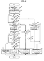
- FIG. 2 is a flow chart showing an example of a control of the opening of a throttle valve;
- FIG. 3 is a time chart illustrating an example of the action of the control of the opening of the throttle valve (without the occurrence of sensor malfunction);
- FIG. 4 is a time chart illustrating an example of the action of the control of the opening of the throttle valve (in case with the occurrence of sensor malfunction and the temperature of the particulate filter at the timing of the occurrence of the malfunction being a specified (predetermined or predeterminable) value or smaller);
- FIG. 5 is a time chart illustrating an example of the action of the control of the opening of the throttle valve (in case with the occurrence of sensor malfunction and the temperature of the particulate filter at the timing of the occurrence of the malfunction being a specified (predetermined or predeterminable) value or larger); and
- FIG. 6 is a flow chart showing another example of a control of the opening of a throttle valve.
-
- A preferred embodiment of the present invention will now be described. It should be understood that even though embodiments are separately described, single features thereof may be combined to additional embodiments.
- The present invention preferably is applied to a
diesel engine 1 shown in FIG. 1. Theengine 1 is a four-cylinder engine for example, having four pistons 3 (one of which is shown) provided therewith which vertically reciprocate in a cylinder bore of an enginemain body 2. A cylinder head of the enginemain body 2 is provided with aninjector 4 correspondingly to each cylinder. Theinjector 4 directly injects fuel into a combustion chamber of the cylinder. - A high-
pressure fuel pump 5 andcommon rail 6 are arranged in a fuel supply passage between a fuel tank, not shown, and theinjector 4. Thepump 5 press-feeds fuel from the fuel tank to thecommon rail 6, and thecommon rail 6 accumulates the press-fed fuel. When theinjector 4 opens its valve, a fuel having been accumulated in thecommon rail 6 is injected at high pressure through one or more injection bores of theinjector 4. The amount of the fuel to be injected is controllable by the adjustment of the valve-opening duration of theinjector 4 and the fuel pressure in thecommon rail 6. The timing of the fuel injection is controllable preferably by the adjustment of the valve-opening timing of theinjector 4. In the drawing, the arrows drawn along the fuel supply passage indicate the direction of fuel flow. - In an
intake passage 10, from the upstream side, there are disposed at least part of the following elements: anair filter 11, an air-sensor such as a air-flow meter 12, acompressor 13 preferably of a turbocharger, anintercooler 14, anintake throttle valve 15 for adjusting the intake amount, an intake throttle valve opening sensor 16 (as preferred first parameter value detection means) for detecting the opening degree of thethrottle valve 15, an intake-air temperature sensor 17, intake-air pressure sensor 18, and/or anintake valve 19, in this order. - In an
exhaust passage 20, from the upstream side, there are disposed at least part of the following elements: anexhaust valve 21, aturbine 22 of the turbocharger, a first exhaust-gas temperature sensor 23, anoxidation catalyst converter 24, a second exhaust-gas temperature sensor 25 (as a preferred third parameter value detection means), an upstream pressure sensor 26 (as a preferred second parameter value detection means), aparticulate filter 27 for trapping exhausted particulate in exhaust gas, a downstream pressure sensor 28 (as a preferred second parameter value detection means), and a third exhaust-gas temperature sensor 29, in this order. Between a relatively upstream portion of theexhaust passage 20 and a (preferably relatively downstream) portion of theintake passage 10, an exhaust gas recirculation (EGR)passage 30 is disposed. In theEGR passage 30, anEGR valve 31 is provided for adjusting or controlling the recirculation amount of the exhaust gas. Theparticulate filter 27 preferably is coated with oxidation catalyst agents including noble metal such as platinum - An engine
rotational speed sensor 41 is attached to a crankcase (not shown) of the enginemain body 2, and acoolant temperature sensor 42 is attached or connected preferably to a cylinder block (not shown). Thecommon rail 6 is provided with a commonrail pressure sensor 43 for detecting the accumulating pressure of fuel. In a passenger compartment (not shown), an acceleratorpedal position sensor 45 is preferably provided for detecting the operational amount of anaccelerator pedal 44. - A
control unit 50 of theengine 1 outputs control signals to theinjector 4 and the high-pressure fuel pump 5 in accordance with the intake-air amount, the intake-air temperature, the intake-air pressure, the temperature of the exhaust-gas flowing into theoxidation catalyst converter 24, the temperature of the exhaust-gas flowing out of theparticulate filter 27, the pressures upstream and downstream of theparticulate filter 27, the engine rotational speed, the coolant temperature, the fuel pressure in thecommon rail 6, and/or the engine load, which are detected by the above-described sensors. - The
control unit 50 calculates a target fuel injection amount by compensating for a basic fuel injection amount by use of the coolant temperature and the intake-air temperature. The basic fuel injection amount is determined from the engine rotational speed detected by the enginerotational speed sensor 41 and the engine load detected preferably by the acceleratorpedal position sensor 45, with the influence of EGR being considered. - The
control unit 50 controls not only theEGR valve 31 but also the opening degree of theintake throttle valve 15 for the adjustment of the EGR amount. The opening degree is increased for the larger engine load (opening degree of the accelerator pedal) and the larger engine rotational speed. - The
control unit 50 estimates or determines the amount of exhausted particulate trapped in theparticulate filter 27 based on the pressure difference between the pressure upstream of theparticulate filter 27 and the pressure downstream of theparticulate filter 27, and determines the initiation timing of the burn-out operation of the exhausted particulate trapped in theparticulate filter 27, or when to initiate the regeneration of theparticulate filter 27. - When the estimated or determined trapped amount reaches a specified (predeterminer or predeterminable) amount or more, the
control unit 50 initiates the regeneration of theparticulate filter 27. That is, thecontrol unit 50 changes the opening degree of theintake throttle valve 15 to a smaller degree than that in non-regeneration state (changes the degree to closing side), and initiates additional fuel injection (post injection) during the expansion stroke after a primary fuel injection performed near the top dead center (TDC) of the compression stroke of thepiston 3. The post injection aims at oxidizing unburned component, caused by the post injection, in theoxidation catalyst converter 24 and theparticulate filter 27 loaded with oxidation catalyst agents to raise the temperature thereof for quickly regenerating theparticulate filter 27. The reduction in the opening degree of theintake throttle valve 15 to smaller than that in the non-regenerating state aims at decreasing the intake-air amount and thus the exhaust-gas amount for efficiently raising the temperature thereof and/or of theparticulate filter 27. - The
control unit 50 checks for the presence of a malfunction of the throttlevalve opening sensor 16. Upon the detection of a malfunction, thecontrol unit 50 controls theintake throttle valve 15 to substantially fully open, unless a specified (predetermined or predeterminable) condition has been fulfilled. The fully opening of theintake throttle valve 15 aims at taking in the sufficient amount of fresh air for ensuring favorable running performance of the vehicle. - In a case where the temperature T of the
particulate filter 27 has been raised by the regeneration operation of theparticulate filter 27 or other factors, abrupt full opening of theintake throttle valve 15 would adversely cause fresh air to abruptly flow in a large amount, and thus abruptly increase oxygen supply, resulting in unduly rise in the temperature T of theparticulate filter 27. This may possibly lead to the melt, defect, and/or hypofunction of theparticulate filter 27. To cope with this, thecontrol unit 50 of theengine 1 according to the embodiment, if a specified (predetermined or predeterminable) condition has been fulfilled, inhibits the full opening of theintake throttle valve 15 in case that a malfunction is detected in the throttlevalve opening sensor 16. - The control of the opening degree of the
intake throttle valve 15 will now be described in detail with reference to the flow chart shown in FIG. 2. As apparent from the above description, thecontrol unit 50 preferably is loaded with a computer program for carrying out the following control flow. The program is preferably stored in a memory (not shown) coupled to thecontrol unit 50. - First, in step S1, the
control unit 50 obtains a variety of values detected by the above-described sensors such as the temperature T of the particulate filter 27 (detected by the second exhaust-gas temperature sensor 25), the exhaust-gas pressure upstream of the particulate filter 27 (detected by the upstream pressure sensor 26), the exhaust-gas pressure downstream of the particulate filter 27 (detected by the downstream pressure sensor 28), and the engine rotational speed. In addition, thecontrol unit 50 calculates the pressure difference between the detected upstream exhaust-gas pressure and the detected downstream exhaust-gas pressure. Then, in step S2, the trapped amount W of particulate trapped in theparticulate filter 27 is calculated or determined or estimated based on the calculated pressure difference. - Next, in step S3, a judgement or determination is made as to whether or not the flag F2 is 1. If NO is judged meaning that the flag F2 is not 1, a judgement or determination is made as to whether or not the trapped amount W is equal to or larger than a specified (predetermined or predeterminable) value α in step S4 (as preferred regeneration initiation judgement means). The initial value of the flag F2 is 0. When the trapped amount W reaches a predetermined or predeterminable value α or larger, the flag F2 is set to 1 in step S9. When the trapped amount W is decreased to a specified (predetermined or predeterminable) value δ or smaller by the regeneration operation, the flag F2 is reset to 0 in step S13.
- If step S4 judges NO meaning that the trapped amount W is not equal to the predetermined or predeterminable value α or larger, the sequence proceeds to step S5 where a judgement or determination or discrimination is made as to whether the presence or absence of a malfunction of the throttle
valve opening sensor 16 provided for detecting the opening degree of the intake throttle valve 15 (as preferred malfunction detecting means). Herein, the malfunction of the throttlevalve opening sensor 16 refers to the condition where its output value is out of a predetermined or predeterminable range (normal range) e.g. due to the brake or short in sensor wiring. In step S5, if the output value is in the predetermined or predeterminable range, the absence of a malfunction (NO) is judged. On the other hand, if the output value is out of the predetermined or predeterminable range, the presence of a malfunction (YES) is judged. - If step S5 judges NO meaning that no sensor malfunction has occurred, a control of the opening degree of the
intake throttle valve 15 is performed in accordance with the operational condition in step S6. If step S5 judges YES meaning that sensor malfunction has occurred, a warning lamp (not shown) is illuminated in step S7, and theintake throttle valve 15 is fully opened in step S8 (as preferred malfunction handling means). - On the other hand, if step S4 judges YES meaning that the trapped amount W is equal to the predetermined or predeterminable value α or larger, the sequence proceeds to step S9, where the flag F2 is set to 1.
- Next, in step S10, a judgement or determination is made as to whether the presence or absence of a malfunction of the throttle
valve opening sensor 16 in the similar manner to step S5 described above (as preferred malfunction detection means). If NO is judged meaning that no sensor malfunction has occurred, the sequence proceeds to step S11 where a judgement or determination is made as to whether or not the trapped amount W is equal to the predetermined or predeterminable value δ or smaller, that is, whether or not the regeneration control of theparticulate filter 27 has reduced the trapped amount W to the predetermined or predeterminable value δ or smaller. The predetermined or predeterminable value δ is preferably preset to smaller than the predetermined or predeterminable value α used in the above-described regeneration initiation. - If step S11 judges NO meaning that the trapped amount W is not equal to the predetermined or predeterminable value δ or smaller, the filter regeneration is implemented by performing the post injection and changing the opening degree of the
intake throttle valve 15 to the closing side in step S12 (as preferred regeneration means). If step S11 judges YES meaning that the trapped amount W is equal to the predetermined or predeterminable value δ or smaller, the flag F2 is set to 0 in step S13; the control of the opening degree of theintake throttle valve 15 is performed in accordance with the operational condition in step S6; and the sequence returns to step S1. In other words, the sequence completes the regeneration of theparticulate filter 27 and shifts to a control for the non-regeneration state. - On the other hand, if step S10 judges YES meaning that sensor malfunction has occurred, the warning lamp is illuminated in step S14 and the post injection is discontinued or reduced in its amount in step S15. The discontinuation or reduction of the post injection aims at suspending the regeneration of the
particulate filter 27, thereby decreasing the temperature T of theparticulate filter 27 quickly and positively. - Next, in step S16, a judgement or determination is made as to whether or not a flag F1 is 1. The initial value of the flag F1 is 0. When the temperature T of the
particulate filter 27 reaches a specified (predetermined or predeterminable) value β or larger, the flag F1 is set to 1 in step S18. When the temperature T is decreased to a specified (predetermined or predeterminable) value γ or smaller by the regeneration operation, the flag F1 is reset to 0 in step S21. - If step S16 judges NO meaning that the flag has not been set to 1, a judgement or determination is made as to whether or not the temperature T of the
particulate filter 27 is equal to the predetermined or predeterminable value p or larger in step S17 (third parameter value detection means). The predetermined or predeterminable value p may be preferably set to approximately 500°C which is reached in the late stage of a standard regeneration control, for example. If the judgement is NO meaning that the temperature T is not equal to β or larger, theintake throttle valve 15 is fully opened, and the sequence returns to step S1. - On the other hand, if step S17 judges YES meaning that the temperature T is equal to β or larger, the flag F1 is set to 1 in step S18 and a judgement is made as to whether or not the temperature T of the
particulate filter 27 is equal to the predetermined or predeterminable value γ or smaller in step S19 (regeneration suppression judgement means). The predetermined or predeterminable value γ is smaller than β. For example, γ may be preferably set to approximately 400°C being lower than β. - If step S19 judges NO meaning that the temperature T is not equal to γ or smaller, the condition of the
intake throttle valve 15 being adjusted to the closing side is maintained in step S20 (as preferred malfunction handling inhibition means) and the sequence returns to step S1. If step S19 judges YES meaning that the temperature T is equal to γ or smaller, the flag F1 is reset to 0 in step S21; theintake throttle valve 15 is fully opened in step S8; and the sequence returns to step S1. - This control acts as will be described with reference to the time charts shown in FIG. 3 through FIG. 5.
- FIG. 3 shows the case without the occurrence of a malfunction of the throttle valve opening sensor 16 (steps S10, S11, S12, S13, and S16 in FIG. 2). As shown, in a condition where the trapped amount W is on gradual increase but has not yet reached the predetermined or predeterminable value α, the opening degree of the
intake throttle valve 15 is controlled in accordance with engine load. When the trapped amount W reaches the predetermined or predeterminable value α (at time t1) as the particulate exhausted by the operation of theengine 1 is trapped and accumulated in theparticulate filter 27, the flag F2 is set to 1; the opening degree of theintake throttle valve 15 is reduced to a smaller degree than that in non-regeneration state; and the post injection is performed, that is, the regeneration control of theparticulate filter 27 is implemented. - Then, the regeneration control causes the exhausted particulate to burn out, so that the trapped amount W gradually decreases and the temperature T of the
particulate filter 27 gradually rises. When the trapped amount W has been decreased to the predetermined or predeterminable value α (at time t2), the flag F2 is reset to 0 and thus the regeneration control, or the post injection and the control of the opening of intake throttle valve to closing side, is ended, and the control shifts to the operational-condition-based control of theintake throttle valve 15. In addition, this results in the gradual drop in the temperature T of theparticulate filter 27. - FIG. 4 shows the case where a malfunction occurs in the throttle
valve opening sensor 16 and the temperature T of theparticulate filter 27 at the timing of the malfunction occurrence is equal to value β or smaller (steps S10, S17, and S8). For the control before the time t11 at which the regeneration control is initiated, its description is omitted because it is similar or the same as that before the time t1 shown in FIG. 3. - As shown, by the regeneration control having been implemented from the time t11, the exhausted particulate burns out to gradually decrease the trapped amount W and to gradually raise the temperature T of the
particulate filter 27. Upon the occurrence of the malfunction of the throttle valve opening sensor 16 (at time t12), the post injection is immediately discontinued, or reduced in its amount, and the judgement or determination is made as to whether or not the temperature T of theparticulate filter 27 is equal to the predetermined or predeterminable value β or larger. At this time, theintake throttle valve 15 is controlled to full open because the temperature T is not equal to the predetermined or predeterminable value β or larger. As a result, the temperature T of theparticulate filter 27 quickly drops with favorable running performance of the vehicle being ensured. The reason for the immediate full open of theintake throttle valve 15 is that the problem of unduly temperature rise is not caused even by the full open of theintake throttle valve 15 because the exhaust particulate trapped in theparticulate filter 27 has not yet actively burned out in the early stage of the regeneration (where the temperature T is not equal to the predetermined or predeterminable value p or larger). - FIG. 5 shows the case where a malfunction occurs in the throttle
valve opening sensor 16 and the temperature T of theparticulate filter 27 at the timing of the malfunction occurrence is equal to value β or larger (steps S10, S17, S19, S20, and S8). For the control before the time t21 at which the regeneration control is initiated, its description is omitted because it is similar or the same as that before the time t1 shown in FIG. 3. - As shown, by the regeneration control having been implemented from the time t21, the exhausted particulate burns out to gradually decrease the trapped amount W and to gradually raise the temperature T of the
particulate filter 27. Upon the occurrence of the malfunction of the throttle valve opening sensor 16 (at time t22), the post injection is immediately discontinued, or reduced in its amount, and the judgement or determination is made as to whether or not the temperature T of theparticulate filter 27 is equal to the predetermined or predeterminable value β or larger. In this case, however, the full open control of the intake throttle valve 15 (indicated by the broken line in FIG. 5) is suspended and thus its opening degree is maintained on the closing side because the temperature T is equal to the predetermined or predeterminable value β or larger, that is, the regeneration of theparticulate filter 27 is in the late stage. Then, the judgement or determination is made as to whether or not the temperature T of theparticulate filter 27 has dropped to the predetermined or predeterminable value γ or smaller. When the temperature T is judged to be equal to the predetermined or predeterminable value γ or smaller (at time t23), that is, the temperature T of theparticulate filter 27 has been sufficiently dropped, theintake throttle valve 15 is fully opened. This control prevents the unduly rise in the temperature T of the particulate filter 27 (indicated by the broken line in FIG. 5) due to the abrupt increase in the oxygen supply to theparticulate filter 27 and the accompanying problem such as melt because the full open control of theintake throttle valve 15 is inhibited in the later stage of the regeneration (the period from time t22 to t23) with the temperature T of theparticulate filter 27 being high. - In the flow chart shown in FIG. 2, in case that a malfunction is detected or judged in the throttle
valve opening sensor 16 during the regeneration of theparticulate filter 27, the timing of the full open control of theintake throttle valve 15 is determined in accordance with the temperature T of theparticulate filter 27. However, the timing may be otherwise determined in accordance with the lapsed time since the initiation of the regeneration of theparticulate filter 27. Such a control will now be described with reference to the flow chart shown in FIG. 6.Step 31 throughstep 39 are similar or the same as step S1 through step S9, respectively, with its description omitted. For other steps, the description is omitted for the same steps as those in FIG. 2. - If step S34 judges YES meaning that the trapped amount W is equal to the specified (predetermined or predeterminable) value α or larger, the sequence proceeds to step S39 where the flag F2 is set to 1, and in step S40, a counter (third parameter value detection means, not shown) is operated to measure a lapsed time C since the regeneration initiation.
- Next, in step S41, a judgement or determination is made as to whether the presence or absence of the malfunction of the throttle
valve opening sensor 16. If NO is judged meaning that no sensor malfunction has occurred, the sequence proceeds to step S42 where a judgement or determination is made as to whether the trapped amount is equal to the specified (predetermined or predeterminable) value δ or smaller. - If step S42 judges NO meaning that the trapped amount W is not equal to the specified (predetermined or predeterminable) value δ or smaller, the filter regeneration is implemented by performing the post injection and changing the opening degree of the
intake throttle valve 15 to the closing side in step S43 (as preferred regeneration means). Ifstep S 42 judges YES meaning that the trapped amount W is equal to the predeterminable value δ or smaller, the flag F2 is set to 0 in step S44; the control of the opening degree of theintake throttle valve 15 is performed in accordance with the operational condition in step S36; and the sequence returns to step S31. In other words, the sequence completes the regeneration of theparticulate filter 27 and shifts to a control for the non-regeneration state. - On the other hand, if step S41 judges YES meaning that sensor malfunction has occurred, the warning lamp is illuminated in step S45 and the post injection is discontinued or reduced in its amount in step S46.
- Next, in step S47, a judgement or determination is made as to whether or not the flag F1 has been set to 1. If NO is judged meaning that the flag F1 is not 1, a judgement or determination is made as to whether or not the lapsed time C is equal to a specified (predetermined or predeterminable) value C1 or smaller in step S48 (a third parameter value detection means). The predetermined or predeterminable value C1 may be preferably set to a time period during which the temperature T of the
particulate filter 27 is raised to approximately 500°C by a standard regeneration control, for example. If YES is judged meaning that the lapsed time C is equal to the predetermined or predeterminable value C1 or smaller, theintake throttle valve 15 is fully opened in step S38, and the sequence returns to step S31. - On the other hand, if step S48 judges NO meaning that the lapsed time C is not equal to the predetermined or predeterminable value C1 or smaller, the flag F1 is set to 1 in step S49 and a judgement or determination is made as to whether or not the lapsed time C is equal to the predetermined or predeterminable value C2 or larger in step S50 (regeneration suppression judgement means). The specified (predetermined or predeterminable) value C2 is greater than C1. For example, C2 may be preferably set to a time period during which the discontinuation of the regeneration causes the temperature T of the
particulate filter 27 to drop to approximately 400°C when the temperature T of theparticulate filter 27 has raised to approximately 500°C in a standard operational condition. - If step S50 judges NO meaning that the lapsed time C is not equal to C2 or larger, the condition of the
intake throttle valve 15 being adjusted to the closing side is maintained in step S51 and the sequence returns to step S31. If step S50 judges YES meaning that the lapsed time C is equal to C2 or larger, the flag F1 is reset to 0 in step S52; theintake throttle valve 15 is fully opened in step S52; and the sequence returns to step S31. - It should be appreciated that though the above-described embodiment changes the opening of the
intake throttle valve 15 during the regeneration operation to a smaller degree (no fixed value) than that in the non-regenerating state in accordance with the engine operational condition, the opening may be changed to a degree equal to or smaller than a specified (predetermined predeterminable) degree (substantially fully closed) regardless of the engine operational condition. - It should be also appreciated that the preferred embodiment of the present invention is described for a diesel engine, but the present invention may apply to gasoline engines or any other engines that may produce carbon particulate. Also, the application of the present invention is not limited to automotive engines, but includes engines in industrial use or engines used for other purposes.
- Moreover, though this embodiment runs the computer program for performing the control of the present invention which has been stored in the memory of the
control unit 50, the program may be stored in a storage medium (e.g. CD-ROM) separate from thecontrol unit 50 or may be implemented in a dedicated circuitry, logic component and/or programmable device (e.g. an PROM, EPROM, EEPROM, ASIC, etc.). - Furthermore, it should be appreciated that even though the invention is described with reference to an engine using a throttle valve for controlling the amount of intake-air, the invention is equally applicable to engines where the amount of intake air is controlled in a different way.
- As described above, the present invention inhibits the opening degree of the intake throttle valve from being widened when the regeneration of the particulate filter or other factors have raised the filter temperature. Accordingly, even when it is demanded that the opening degree of the intake throttle valve be widened to cope with a malfunction of the throttle valve sensor, defects in the filter, possibly caused by the unduly temperature rise of the particulate filter, is prevented.
Claims (9)
- A control apparatus for an engine (1), the engine (1) being equipped with trapping means (27) for trapping exhausted particulate in an exhaust passage (20) of the engine (1), comprising,
first parameter value detection means (16) for detecting a parameter value associated with amount of intake-air;
second parameter value detection means (26, 28) for detecting at least one parameter value associated with the amount of exhausted particulate trapped in the trapping means (27);
regeneration initiation judgement means (50) for making an initiation judgement that a burn-out operation of the exhausted particulate trapped in the trapping means (27) should be initiated in accordance with a detection of said second parameter value detection means (26, 28);
regeneration means (50) for, when the initiation judgement is made by said regeneration initiation judgement means (50), regenerating the trapping means (27) by including reducing the amount of intake-air to a smaller degree than that attained in accordance with the engine operational condition during non-regeneration state;
malfunction detection means (50) for detecting a malfunction of said first parameter value detection means (16);
malfunction handling means (50) for handling the malfunction by increasing the amount of intake-air in case said malfunction detection means (50) detects the malfunction of said first parameter value detection means (16); and
malfunction handling inhibition means (50) for inhibiting an operation of said malfunction handling means (50) during a regeneration operation of said regeneration means (50) even in case said malfunction detection means (50) detects a malfunction of said first parameter value detection means (16). - The control apparatus for an engine (1) as defined in claim 1 further comprising,
third parameter value detection means (25, 50) for detecting a parameter value (T; C) associated with the progress of the regeneration by the regeneration means (50),
wherein said malfunction handling inhibition means (50) inhibits the operation of said malfunction handling means (50) only when the progress in the regeneration detected by said third parameter value detection means (25, 50) is greater than a predetermined or predeterminable degree. - The control apparatus for an engine (1) as defined in claim 2,
wherein said regeneration means (5), when the initiation judgement is made by said regeneration initiation judgement means (50), further controls a fuel injector (4) of the engine (1) to perform a post injection during the expansion stroke after a primary injection near the top dead center of the compression stroke, and
wherein said regeneration means (50) reduces the amount of the post injection when said malfunction handling inhibition means (50) inhibits the operation of said malfunction handling means (50). - The control apparatus for an engine (1) as defined in claim 2 or 3 further comprising,
regeneration suppression judgement means (50) for judging that the reduction in the amount of the post injection has suppressed the progress in the regeneration of the trapping means (27) based on the detection by said third parameter value detection means (25, 50),
wherein said malfunction handling inhibition means (50) discontinues the inhibition of the operation of said malfunction handling means (50) when said regeneration suppression judgement means (50) judges that the progress in the regeneration is suppressed. - The control apparatus for an engine (1) as defined in any one of claims 2 to 4,
wherein said third parameter value detection means (25, 50) detects any one of a parameter value (T; C) associated with the temperature (T) of the trapping means (27) and the lapsed time (C) since said regeneration means (50) initiated its operation. - An engine (1) equipped with the control apparatus as defined in any one of claims 1 to 5.
- A diesel engine (1) equipped with the control apparatus as defined in any one of claims 1 to 5.
- A control method of an engine (1), the engine being equipped with trapping means (27) for trapping exhausted particulate in an exhaust passage (20) of the engine (1), comprising the following steps of:detecting a first parameter value associated with the amount of intake-air;detecting at least one second parameter value associated with the amount of exhausted particulate trapped in the trapping means (27);making an initiation judgement that a burn-out operation of the exhausted particulate trapped in the trapping means (27) should be initiated based on a detection of the second parameter value;regenerating the trapping means (27) upon the initiation judgement by reducing the amount of intake-air to a smaller degree than that attained in accordance with the engine operational condition during non-regeneration state;detecting a malfunction in said step of detecting the first parameter value;handling a malfunction by increasing the amount of intake-air in case the malfunction is detected in said step of detecting the first parameter value; andinhibiting the handling of the malfunction during the regeneration of the trapping means even in case the malfunction is detected in said step of detecting the first parameter value.
- Computer program product which, when loaded onto a computer for use in a control apparatus for an engine (1) being equipped with trapping means (27) for trapping exhausted particulate in an exhaust passage (20) of the engine (1), carries out the control method of an engine according to claim 8.
Applications Claiming Priority (2)
| Application Number | Priority Date | Filing Date | Title |
|---|---|---|---|
| JP2003094500 | 2003-03-31 | ||
| JP2003094500A JP3915728B2 (en) | 2003-03-31 | 2003-03-31 | Engine control device |
Publications (2)
| Publication Number | Publication Date |
|---|---|
| EP1464815A1 true EP1464815A1 (en) | 2004-10-06 |
| EP1464815B1 EP1464815B1 (en) | 2006-01-04 |
Family
ID=32844616
Family Applications (1)
| Application Number | Title | Priority Date | Filing Date |
|---|---|---|---|
| EP04007119A Expired - Lifetime EP1464815B1 (en) | 2003-03-31 | 2004-03-24 | Control apparatus and method for internal combustion engine |
Country Status (3)
| Country | Link |
|---|---|
| EP (1) | EP1464815B1 (en) |
| JP (1) | JP3915728B2 (en) |
| DE (1) | DE602004000297T2 (en) |
Cited By (2)
| Publication number | Priority date | Publication date | Assignee | Title |
|---|---|---|---|---|
| FR2867509A1 (en) * | 2004-03-15 | 2005-09-16 | Denso Corp | EXHAUST GAS PURIFYING SYSTEM OF INTERNAL COMBUSTION ENGINE |
| EP1741885A3 (en) * | 2005-05-18 | 2007-12-26 | HONDA MOTOR CO., Ltd. | Exhaust gas purifying apparatus for internal combustion engine |
Families Citing this family (1)
| Publication number | Priority date | Publication date | Assignee | Title |
|---|---|---|---|---|
| JP5530226B2 (en) * | 2010-03-09 | 2014-06-25 | ヤンマー株式会社 | Engine exhaust gas treatment system |
Citations (2)
| Publication number | Priority date | Publication date | Assignee | Title |
|---|---|---|---|---|
| US5384707A (en) * | 1990-12-07 | 1995-01-24 | Ford Motor Company | Diagnostic airflow measurement |
| WO2002031324A1 (en) * | 2000-10-13 | 2002-04-18 | Toyota Jidosha Kabushiki Kaisha | Exhaust emission control device of internal combustion engine |
-
2003
- 2003-03-31 JP JP2003094500A patent/JP3915728B2/en not_active Expired - Fee Related
-
2004
- 2004-03-24 DE DE602004000297T patent/DE602004000297T2/en not_active Expired - Lifetime
- 2004-03-24 EP EP04007119A patent/EP1464815B1/en not_active Expired - Lifetime
Patent Citations (3)
| Publication number | Priority date | Publication date | Assignee | Title |
|---|---|---|---|---|
| US5384707A (en) * | 1990-12-07 | 1995-01-24 | Ford Motor Company | Diagnostic airflow measurement |
| WO2002031324A1 (en) * | 2000-10-13 | 2002-04-18 | Toyota Jidosha Kabushiki Kaisha | Exhaust emission control device of internal combustion engine |
| EP1331371A1 (en) * | 2000-10-13 | 2003-07-30 | Toyota Jidosha Kabushiki Kaisha | Exhaust emission control device of internal combustion engine |
Cited By (3)
| Publication number | Priority date | Publication date | Assignee | Title |
|---|---|---|---|---|
| FR2867509A1 (en) * | 2004-03-15 | 2005-09-16 | Denso Corp | EXHAUST GAS PURIFYING SYSTEM OF INTERNAL COMBUSTION ENGINE |
| US7313913B2 (en) | 2004-03-15 | 2008-01-01 | Denso Corporation | Exhaust gas purification system of internal combustion engine |
| EP1741885A3 (en) * | 2005-05-18 | 2007-12-26 | HONDA MOTOR CO., Ltd. | Exhaust gas purifying apparatus for internal combustion engine |
Also Published As
| Publication number | Publication date |
|---|---|
| DE602004000297D1 (en) | 2006-03-30 |
| EP1464815B1 (en) | 2006-01-04 |
| DE602004000297T2 (en) | 2006-09-14 |
| JP3915728B2 (en) | 2007-05-16 |
| JP2004301009A (en) | 2004-10-28 |
Similar Documents
| Publication | Publication Date | Title |
|---|---|---|
| CN101965445B (en) | engine | |
| US7082754B2 (en) | Regeneration of diesel particulate filter | |
| US20080196395A1 (en) | Exhaust Gas Purification System For Internal Combustion Engine | |
| EP1722087B1 (en) | Exhaust gas purifying apparatus for internal combustion engine | |
| EP1662101A1 (en) | Exhaust emission control device of internal combustion engine | |
| EP1669565A1 (en) | Exhaust gas purifying apparatus for internal combustion engine | |
| JP2009281144A (en) | Control device for internal combustion engine with turbocharger | |
| EP1736658A1 (en) | Control system for internal combustion engine | |
| EP1464818B1 (en) | Control apparatus for an engine, engine, control method of an engine, and computer program product | |
| JP3876778B2 (en) | Engine fuel injection control device | |
| JP6036533B2 (en) | PM accumulation amount estimation device and exhaust purification system for internal combustion engine | |
| EP2211044A1 (en) | EGR controller and EGR control method for internal combustion engine | |
| EP1903200B1 (en) | Exhaust gas purification system of internal combustion engine | |
| EP1662122A2 (en) | Exhaust emission control device of internal combustion engine | |
| JP2010169032A (en) | Engine control device | |
| JP2006316746A (en) | Exhaust gas purification device for internal combustion engine | |
| EP1464815B1 (en) | Control apparatus and method for internal combustion engine | |
| JP4710666B2 (en) | EGR system control method and EGR system | |
| JP4400535B2 (en) | Fuel injection control device for internal combustion engine | |
| JP2014031779A (en) | Deterioration diagnostic device of catalyst | |
| JP5247555B2 (en) | Engine control device | |
| JP2021021360A (en) | Control device of engine | |
| JP4447510B2 (en) | Exhaust gas purification device for internal combustion engine | |
| EP1726807B1 (en) | Engine output control system for internal combustion engine | |
| JP5796277B2 (en) | Exhaust gas purification system |
Legal Events
| Date | Code | Title | Description |
|---|---|---|---|
| PUAI | Public reference made under article 153(3) epc to a published international application that has entered the european phase |
Free format text: ORIGINAL CODE: 0009012 |
|
| AK | Designated contracting states |
Kind code of ref document: A1 Designated state(s): AT BE BG CH CY CZ DE DK EE ES FI FR GB GR HU IE IT LI LU MC NL PL PT RO SE SI SK TR |
|
| AX | Request for extension of the european patent |
Extension state: AL LT LV MK |
|
| 17P | Request for examination filed |
Effective date: 20050105 |
|
| 17Q | First examination report despatched |
Effective date: 20050204 |
|
| GRAP | Despatch of communication of intention to grant a patent |
Free format text: ORIGINAL CODE: EPIDOSNIGR1 |
|
| AKX | Designation fees paid |
Designated state(s): DE |
|
| GRAS | Grant fee paid |
Free format text: ORIGINAL CODE: EPIDOSNIGR3 |
|
| GRAA | (expected) grant |
Free format text: ORIGINAL CODE: 0009210 |
|
| AK | Designated contracting states |
Kind code of ref document: B1 Designated state(s): DE |
|
| REF | Corresponds to: |
Ref document number: 602004000297 Country of ref document: DE Date of ref document: 20060330 Kind code of ref document: P |
|
| PLBE | No opposition filed within time limit |
Free format text: ORIGINAL CODE: 0009261 |
|
| STAA | Information on the status of an ep patent application or granted ep patent |
Free format text: STATUS: NO OPPOSITION FILED WITHIN TIME LIMIT |
|
| 26N | No opposition filed |
Effective date: 20061005 |
|
| PGFP | Annual fee paid to national office [announced via postgrant information from national office to epo] |
Ref country code: DE Payment date: 20150317 Year of fee payment: 12 |
|
| REG | Reference to a national code |
Ref country code: DE Ref legal event code: R119 Ref document number: 602004000297 Country of ref document: DE |
|
| PG25 | Lapsed in a contracting state [announced via postgrant information from national office to epo] |
Ref country code: DE Free format text: LAPSE BECAUSE OF NON-PAYMENT OF DUE FEES Effective date: 20161001 |