EP1464784A1 - Strip hinge composed of flexible strips of fiber reinforced synthetic material - Google Patents
Strip hinge composed of flexible strips of fiber reinforced synthetic material Download PDFInfo
- Publication number
- EP1464784A1 EP1464784A1 EP03447081A EP03447081A EP1464784A1 EP 1464784 A1 EP1464784 A1 EP 1464784A1 EP 03447081 A EP03447081 A EP 03447081A EP 03447081 A EP03447081 A EP 03447081A EP 1464784 A1 EP1464784 A1 EP 1464784A1
- Authority
- EP
- European Patent Office
- Prior art keywords
- hinge
- layer
- reinforcing material
- opposite
- mixture
- Prior art date
- Legal status (The legal status is an assumption and is not a legal conclusion. Google has not performed a legal analysis and makes no representation as to the accuracy of the status listed.)
- Withdrawn
Links
- 239000000835 fiber Substances 0.000 title claims abstract description 20
- 229920002994 synthetic fiber Polymers 0.000 title description 2
- 239000012779 reinforcing material Substances 0.000 claims abstract description 45
- 239000000463 material Substances 0.000 claims description 22
- 239000000203 mixture Substances 0.000 claims description 13
- 229920005989 resin Polymers 0.000 claims description 11
- 239000011347 resin Substances 0.000 claims description 11
- 239000012815 thermoplastic material Substances 0.000 claims description 11
- 229920001187 thermosetting polymer Polymers 0.000 claims description 9
- -1 polyethylene Polymers 0.000 claims description 8
- 239000004744 fabric Substances 0.000 claims description 7
- 229920002635 polyurethane Polymers 0.000 claims description 6
- 239000004814 polyurethane Substances 0.000 claims description 6
- 229920001971 elastomer Polymers 0.000 claims description 5
- 239000000806 elastomer Substances 0.000 claims description 5
- 239000013536 elastomeric material Substances 0.000 claims description 4
- 229920002857 polybutadiene Polymers 0.000 claims description 4
- 239000004698 Polyethylene Substances 0.000 claims description 3
- 229920000573 polyethylene Polymers 0.000 claims description 3
- 238000009954 braiding Methods 0.000 claims description 2
- 238000009732 tufting Methods 0.000 claims description 2
- 229920006337 unsaturated polyester resin Polymers 0.000 claims description 2
- 229920001567 vinyl ester resin Polymers 0.000 claims description 2
- 239000010410 layer Substances 0.000 description 29
- 238000000034 method Methods 0.000 description 4
- 239000002131 composite material Substances 0.000 description 3
- 239000000853 adhesive Substances 0.000 description 2
- 230000001070 adhesive effect Effects 0.000 description 2
- 238000005452 bending Methods 0.000 description 2
- 238000010276 construction Methods 0.000 description 2
- 238000005470 impregnation Methods 0.000 description 2
- 230000002787 reinforcement Effects 0.000 description 2
- OKTJSMMVPCPJKN-UHFFFAOYSA-N Carbon Chemical compound [C] OKTJSMMVPCPJKN-UHFFFAOYSA-N 0.000 description 1
- 229920000742 Cotton Polymers 0.000 description 1
- 241000208202 Linaceae Species 0.000 description 1
- 235000004431 Linum usitatissimum Nutrition 0.000 description 1
- 239000004952 Polyamide Substances 0.000 description 1
- 239000004743 Polypropylene Substances 0.000 description 1
- 230000006978 adaptation Effects 0.000 description 1
- 229920003235 aromatic polyamide Polymers 0.000 description 1
- 229910052799 carbon Inorganic materials 0.000 description 1
- 230000000295 complement effect Effects 0.000 description 1
- 150000001875 compounds Chemical class 0.000 description 1
- 239000002178 crystalline material Substances 0.000 description 1
- 239000002657 fibrous material Substances 0.000 description 1
- 239000003365 glass fiber Substances 0.000 description 1
- 229910052500 inorganic mineral Inorganic materials 0.000 description 1
- 239000012212 insulator Substances 0.000 description 1
- 238000009940 knitting Methods 0.000 description 1
- 238000004519 manufacturing process Methods 0.000 description 1
- 239000002184 metal Substances 0.000 description 1
- 239000011707 mineral Substances 0.000 description 1
- 239000004033 plastic Substances 0.000 description 1
- 229920003023 plastic Polymers 0.000 description 1
- 229920002647 polyamide Polymers 0.000 description 1
- 229920000728 polyester Polymers 0.000 description 1
- 229920001155 polypropylene Polymers 0.000 description 1
- 230000003014 reinforcing effect Effects 0.000 description 1
- 239000002356 single layer Substances 0.000 description 1
- 239000000126 substance Substances 0.000 description 1
- 229920001169 thermoplastic Polymers 0.000 description 1
- 239000004416 thermosoftening plastic Substances 0.000 description 1
- 238000003466 welding Methods 0.000 description 1
- 210000002268 wool Anatomy 0.000 description 1
Images
Classifications
-
- E—FIXED CONSTRUCTIONS
- E05—LOCKS; KEYS; WINDOW OR DOOR FITTINGS; SAFES
- E05D—HINGES OR SUSPENSION DEVICES FOR DOORS, WINDOWS OR WINGS
- E05D9/00—Flaps or sleeves specially designed for making from particular material, e.g. hoop-iron, sheet metal, plastics
-
- E—FIXED CONSTRUCTIONS
- E05—LOCKS; KEYS; WINDOW OR DOOR FITTINGS; SAFES
- E05D—HINGES OR SUSPENSION DEVICES FOR DOORS, WINDOWS OR WINGS
- E05D1/00—Pinless hinges; Substitutes for hinges
- E05D1/02—Pinless hinges; Substitutes for hinges made of one piece
-
- E—FIXED CONSTRUCTIONS
- E05—LOCKS; KEYS; WINDOW OR DOOR FITTINGS; SAFES
- E05Y—INDEXING SCHEME ASSOCIATED WITH SUBCLASSES E05D AND E05F, RELATING TO CONSTRUCTION ELEMENTS, ELECTRIC CONTROL, POWER SUPPLY, POWER SIGNAL OR TRANSMISSION, USER INTERFACES, MOUNTING OR COUPLING, DETAILS, ACCESSORIES, AUXILIARY OPERATIONS NOT OTHERWISE PROVIDED FOR, APPLICATION THEREOF
- E05Y2900/00—Application of doors, windows, wings or fittings thereof
- E05Y2900/10—Application of doors, windows, wings or fittings thereof for buildings or parts thereof
- E05Y2900/13—Type of wing
- E05Y2900/132—Doors
Definitions
- the present invention relates to a hinge for hingedly connecting a first and a second device along at least part of a length of a hinge axis between them, according to the preamble of the first claim.
- the hinges known in the art consist of two parts rotatably mounted with respect to each other through a pen.
- one or a plurality of cylindrical protrusions are provided, which are to be received in corresponding recesses on the second part.
- one or a plurality of annular protrusions are provided, which are to be received in corresponding recesses on the first part.
- the first and second part are connected by aligning the central hole of the annular protrusions on the first and second part and by passing a pen through the aligned central holes.
- the first hinge part is mounted to or provided on a first panel, the second part being mounted to or provided on a second panel.
- the hinge of the present invention comprises
- the hinge of the present invention being made of a composite material presents the advantages of being suitable for use with a large variety of devices, shapes and materials that need to be hingedly connected.
- the shape of the hinge in particular the shape of the first and second part that are connected to respectively the first and second device, easily adapts itself to the shape of the devices to be connected. This in contrast to the state of the art hinges the shape of which has to be adapted to the devices to be connected already in the production stage thereof.
- This versatility of the composite material is combined with a reduced weight as compared to existing hinges, while providing improved resistance to wearing, combined with the property that the hinge may be rotated over an angle of more than 180°, often 270 or even 360° without necessitating any adaptation of the mechanical construction of the hinge or the use of dedicated parts. This is particularly advantageous when envisaging the use of the hinge of this invention for connecting a container door to a container.
- the first and second layer comprise a sheet, a fabric or mat of a woven or non-woven, a stitched non-crimp fabric or a braided fabric of fibrous reinforcing material.
- the connection of both layers is facilitated when using a woven, braided or stitched non-crimp fabric or mat, the fibres extending under an angle of between 0 and 180° with respect to the hinge axis. Nevertheless, an angle between 30° and 60° and between 120° and 150° with respect to the hinge axis is preferred as in that way an optimum reinforcement at the position of the hinge axis is obtained.
- the fibrous reinforcing material is built up of fibres that extend in various directions, in particular it is preferred that the fibrous material is built up of fibres extending in perpendicular directions.
- the man skilled in the art will be able to choose the appropriate fibrous reinforcing material depending on the intended use of the hinge and the loads to which the hinge is to be subjected.
- the first and second layer of fibrous reinforcing material may be connected to each other by any means and in any way known to the man skilled in the art.
- the first and second layer may be chemically bonded to each other, be connected by means of an adhesive or be mechanically connected, the latter mechanical connection being preferred.
- the mechanical connection may be achieved according to any method known to the man skilled in the art and will usually be adapted by the man skilled in the art to the nature of the fibrous reinforcing material of which the first and second layer are made.
- the mechanical connection may for example be achieved through welding, stapling, needling, braiding, knitting, tufting or flocking.
- the direction in which the connection is established is not critical to the invention and will usually be adapted by the man skilled in the art to the nature of the first and second fibrous reinforcing material.
- the connection is preferably established in a zigzag manner.
- the zigzag preferably extends under an angle of between 30 and 60° with respect to the hinge axis.
- the first and second layer may be made of the same or a different of fibrous reinforcing material.
- the first and second layer may comprise one single layer of fibrous reinforcing material or a plurality of superimposed layers, that may be connected to each other or not.
- Suitable fibrous reinforcing materials for use with the present invention comprise metal fibres, mineral fibres for example glass fibres, carbon fibres, wool, cotton, flax etc.; synthetic fibres for example polyester, polypropylene, polyethylene, polyamide or mixtures of two or more of these fibres.
- aramid fibres is preferred.
- twined or twisted fibres even if the basic material of which they are made has a lower elongation to break ratio. The twisting and twining techniques have been found to improve the elongation to break ratio.
- the first and second layer are impregnated with a thermoplastic material or a mixture of two or more thermoplastic materials, a thermosetting resin or a mixture of two or more different thermosetting resins, an elastomeric material or a mixture of two or more elastomers, or a mixture of two or more thermoplastic materials, thermosetting resins and elastomers.
- elastomers and thermoplastic materials are preferred as they show a good flexibility at room temperature or bending strain, combined with a good bending strength.
- the thus impregnated fibrous reinforcing material offers the advantage of being a thermal insulator and of providing a good resistance to wearing.
- the fibrous reinforcing material is rather supple, after impregnation and mounting to the devices to be connected, it shows a sufficient strength combined with the flexibility needed to allow rotating the hingedly connected first and second devices with respect to each other. Furthermore, it may be easily built in a wide variety of plastic materials in such a way that the connection of the fibrous reinforcing sheets is hardly visible.
- thermoplastic materials may be used, amorphous materials, crystalline as well as semi-crystalline materials. By selecting the appropriate material a more or less supple hinge or a hinge with a better strength and wearing resistance may be obtained.
- suitable thermoplastics include one or more materials selected from the group of polyurethane, polyethylene, polypropylene, ethylene-propylene copolymers, polybutadiene rubber or a mixture thereof.
- thermosetting resins may be used for impregnating the fibrous reinforcing material, for example a material selected from the group of polyurethane, vinylester resins, unsaturated polyester resins, or a mixture of two or more of these materials.
- Suitable elastomers include polyurethane, polypropylene, ethylene-propylene copolymers, polybutadiene rubber. These materials may be crystalline, semi crystalline or amorphous, depending on the envisaged flexibility and load bearing capacity.
- the invention also relates to an assembly comprising a first and a second device that are hingedly connected to each other by means of the above described hinge.
- first and second fibre reinforcing material at a first side of the connection defining the first part define between them a first free space for receiving a first device.
- the opposite layers of first and second fibre reinforcing material of the second part define the second part with a second free space for receiving a second device.
- the present invention also relates to a container comprising a container wall hingedly connected to a container door by means of the hinge of the present invention.
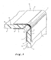
- Figure 1 shows a view to the hinge of the present invention.
- the hinge 10 of the present invention comprises a first 1 and a second 2 layer of a fibrous reinforcing material, that are connected to each other along a hinge axis 3.
- the fibrous reinforcing material is impregnated with an elastomeric material, a thermoplastic material or a thermosetting resin or a combination of two or more of these materials.
- connection 4 may be continuous or may be interrupted, and may extend over the entire length of the hinge axis or over only part thereof, depending on the intended use of the hinge 1.
- the connection 4 will usually extend over a certain width, which will be adapted to the nature of the fibrous reinforcing material 1, 2, the technique with which the connection is achieved, the nature of the material used to effectuate the connection and the nature of the devices that need be connected.
- the first layer 1 extends substantially flat.
- the second layer 2 is bent 15, 16 towards the first layer 1 so as to contact the first layer 1 at the position of the connection 4.
- a first and second pocket 5, 6 are formed for receiving a first and second device 11, 12 that need to be hingedly connected. It is however preferred to use the hinge 10 of the present invention for connecting a first and a second panel 11, 12.
- the first and second panel 11, 12 will usually have in the vicinity of the connection 4, respectively a first and a second end part with a complementary shape.
- the hinge 1 of the present invention is suitable for hingedly connecting a wide variety of devices. Suitable examples include the hinged connection of a door to a container, the hinged connection of two or more panels, the hinged connection of a door to a wall of a building, an air plane, roller doors comprising a plurality of door panels hingedly connected to each other.
- a fireproof door construction can be obtained.
- opposite faces 8, 9 of the first panel 11 are connected to respectively the first and second layer of impregnated fibrous reinforcing material 1, 2.
- connection of both faces 8, 9 of the first panel may be effectuated using the same technique and the same material or in a different manner or using different materials.
- the connection may be established mechanically, for example through stapling, by means of screws, or through chemical bonding, for example by means of an adhesive or a compound which is capable of chemically reacting with both the material of the first panel 11 and the impregnation material for the first and/or second fibrous reinforcement 1, 2.
- Opposite faces 13, 14 of the second panel 12 are connected to respectively the first and second layer of impregnated fibrous reinforcing material 1, 2 in the same or a different manner as compared to the first panel 11.
- the contact surface 7 between the first and second layer of impregnated fibrous reinforcing material 1, 2 and the first and second panel 11, 12 will be sufficiently large.
- the assembly of the present invention may further comprise means for locking the first device to a further device or to a frame to which the first device is mounted.
- the assembly of the present invention may comprise locking means for locking the first or second panel or both to a frame or a further panel.
- the side of the first or second panel 1, 2 facing the frame is provided with a protrusion and the frame or further panel are provided with a corresponding recesses for releasably receiving the protrusion.
- the releasable locking may be accomplished in any manner known to the man skilled in the art, for example in a mechanic manner, by means of co-operating magnets.
- the frame is made of a composite material and comprises a hollow part.
- the hollow part is for example connected to a pressure device or contains mechanical means for expanding the hollow part.
- the protrusion on the first panel 1 comprises means for engaging this recess. When locked into the recess, unlocking of the protrusion is achieved by applying a pressure to the hollow part of the frame or by mechanically expanding the hollow part.
Landscapes
- Engineering & Computer Science (AREA)
- Mechanical Engineering (AREA)
- Laminated Bodies (AREA)
Abstract
The present invention relates to a hinge (10) for hingedly connecting a first
and a second device (11, 12) along at least part of a length of a hinge axis
(4) between them. The hinge (10) of the present invention comprises a
first layer (1) of a first fibre reinforcing material and an opposite second
layer (2) of a second fibre reinforcing material, the first layer (1) of the first
fibre reinforcing material being connected to the second layer (2) of the
second fibre reinforcing material over at least part of the length of the
hinge axis (4), the connection defining on opposite sides thereof a
hingedly connected first and a second part (5, 6) comprising the opposite
first and second layers of fibre reinforcing material (1, 2). The hinge of the
present invention is suitable for use in a wide variety of applications, for
example the hinged connection of a door to a container, the hinged
connection of two or more panels, the hinged connection of a door to a
wall of a building or an air plane, roller doors comprising a plurality of door
panels hingedly connected to each other.
Description
- The present invention relates to a hinge for hingedly connecting a first and a second device along at least part of a length of a hinge axis between them, according to the preamble of the first claim.
- The hinges known in the art consist of two parts rotatably mounted with respect to each other through a pen. Along the side of the first part that contacts a corresponding side of the second part, one or a plurality of cylindrical protrusions are provided, which are to be received in corresponding recesses on the second part. Likewise, along the side of the second part contacting the corresponding side of the first side, one or a plurality of annular protrusions are provided, which are to be received in corresponding recesses on the first part. The first and second part are connected by aligning the central hole of the annular protrusions on the first and second part and by passing a pen through the aligned central holes. In practice, usually the first hinge part is mounted to or provided on a first panel, the second part being mounted to or provided on a second panel.
- These known hinges however present the disadvantage that the annular protrusions of the first and second part need to be well aligned to allow mounting the hinge. This has been found to be particularly laborious in case the annular protrusions of the hinge and the panel to which are provided, are made from one part.
- It is the aim of the present invention to provide a new hinge, which may be produced in a simple manner and which is suitable for use with a large variety of materials and devices.
- This is achieved according to the present invention with the technical features of the first claim.
- The hinge of the present invention comprises
- (a) a first layer or sheet of a first fibre reinforcing material and an opposite second layer of a second fibre reinforcing material. The first and second fibrous reinforcing material may be the same or different.
- (b) the first layer of the first fibre reinforcing material is connected to the second layer of the second fibrous reinforcing material at the position of the hinge axis, over at least part of the length of the hinge axis.
- (c) On opposite sides of the connection of the first layer of fibrous reinforcing material and the second layer of fibrous reinforcing material, hingedly connected first and a second parts are defined. The first part comprises a part of the opposite first and second layers of fibre reinforcing material on one side of the connection. The second part comprises a part of the opposite first and second layers of fibre reinforcing material on the opposite side of the connection.
-
- The hinge of the present invention being made of a composite material presents the advantages of being suitable for use with a large variety of devices, shapes and materials that need to be hingedly connected. The shape of the hinge, in particular the shape of the first and second part that are connected to respectively the first and second device, easily adapts itself to the shape of the devices to be connected. This in contrast to the state of the art hinges the shape of which has to be adapted to the devices to be connected already in the production stage thereof. This versatility of the composite material is combined with a reduced weight as compared to existing hinges, while providing improved resistance to wearing, combined with the property that the hinge may be rotated over an angle of more than 180°, often 270 or even 360° without necessitating any adaptation of the mechanical construction of the hinge or the use of dedicated parts. This is particularly advantageous when envisaging the use of the hinge of this invention for connecting a container door to a container.
- In the hinge of this invention, the first and second layer comprise a sheet, a fabric or mat of a woven or non-woven, a stitched non-crimp fabric or a braided fabric of fibrous reinforcing material. The connection of both layers is facilitated when using a woven, braided or stitched non-crimp fabric or mat, the fibres extending under an angle of between 0 and 180° with respect to the hinge axis. Nevertheless, an angle between 30° and 60° and between 120° and 150° with respect to the hinge axis is preferred as in that way an optimum reinforcement at the position of the hinge axis is obtained. To improve the mechanical stability of the hinge it is preferred that the fibrous reinforcing material is built up of fibres that extend in various directions, in particular it is preferred that the fibrous material is built up of fibres extending in perpendicular directions. The man skilled in the art will be able to choose the appropriate fibrous reinforcing material depending on the intended use of the hinge and the loads to which the hinge is to be subjected.
- The first and second layer of fibrous reinforcing material may be connected to each other by any means and in any way known to the man skilled in the art. For example the first and second layer may be chemically bonded to each other, be connected by means of an adhesive or be mechanically connected, the latter mechanical connection being preferred.
- The mechanical connection may be achieved according to any method known to the man skilled in the art and will usually be adapted by the man skilled in the art to the nature of the fibrous reinforcing material of which the first and second layer are made. The mechanical connection may for example be achieved through welding, stapling, needling, braiding, knitting, tufting or flocking. The direction in which the connection is established is not critical to the invention and will usually be adapted by the man skilled in the art to the nature of the first and second fibrous reinforcing material. In order to obtain an optimum connection and to minimise the risk to deformation of the connection and shifting of the connected panels with respect to each other in length direction of the hinge axis, the connection is preferably established in a zigzag manner. The zigzag preferably extends under an angle of between 30 and 60° with respect to the hinge axis.
- The first and second layer may be made of the same or a different of fibrous reinforcing material. The first and second layer may comprise one single layer of fibrous reinforcing material or a plurality of superimposed layers, that may be connected to each other or not. Suitable fibrous reinforcing materials for use with the present invention comprise metal fibres, mineral fibres for example glass fibres, carbon fibres, wool, cotton, flax etc.; synthetic fibres for example polyester, polypropylene, polyethylene, polyamide or mixtures of two or more of these fibres. However, because of its high elongation to break ratio, the use of aramid fibres is preferred. It is however also possible to use twined or twisted fibres, even if the basic material of which they are made has a lower elongation to break ratio. The twisting and twining techniques have been found to improve the elongation to break ratio.
- After having been connected to each other, the first and second layer are impregnated with a thermoplastic material or a mixture of two or more thermoplastic materials, a thermosetting resin or a mixture of two or more different thermosetting resins, an elastomeric material or a mixture of two or more elastomers, or a mixture of two or more thermoplastic materials, thermosetting resins and elastomers. However, elastomers and thermoplastic materials are preferred as they show a good flexibility at room temperature or bending strain, combined with a good bending strength. The thus impregnated fibrous reinforcing material offers the advantage of being a thermal insulator and of providing a good resistance to wearing. Moreover, although the fibrous reinforcing material is rather supple, after impregnation and mounting to the devices to be connected, it shows a sufficient strength combined with the flexibility needed to allow rotating the hingedly connected first and second devices with respect to each other. Furthermore, it may be easily built in a wide variety of plastic materials in such a way that the connection of the fibrous reinforcing sheets is hardly visible.
- Within the scope of this invention, a wide variety of thermoplastic materials may be used, amorphous materials, crystalline as well as semi-crystalline materials. By selecting the appropriate material a more or less supple hinge or a hinge with a better strength and wearing resistance may be obtained. Examples of suitable thermoplastics include one or more materials selected from the group of polyurethane, polyethylene, polypropylene, ethylene-propylene copolymers, polybutadiene rubber or a mixture thereof. Within the scope of this invention, a wide variety of thermosetting resins may be used for impregnating the fibrous reinforcing material, for example a material selected from the group of polyurethane, vinylester resins, unsaturated polyester resins, or a mixture of two or more of these materials. Examples of suitable elastomers include polyurethane, polypropylene, ethylene-propylene copolymers, polybutadiene rubber. These materials may be crystalline, semi crystalline or amorphous, depending on the envisaged flexibility and load bearing capacity.
- The invention also relates to an assembly comprising a first and a second device that are hingedly connected to each other by means of the above described hinge.
- In this assembly, the opposite layers of first and second fibre reinforcing material at a first side of the connection defining the first part, define between them a first free space for receiving a first device. Similarly, the opposite layers of first and second fibre reinforcing material of the second part define the second part with a second free space for receiving a second device.
- It is however preferred to connect opposite first and second sides of the first device to respectively the first and second layer of the first part, and to connect opposite first and second sides of the second device to respectively the first and second layer of the second device.
- The present invention also relates to a container comprising a container wall hingedly connected to a container door by means of the hinge of the present invention.
- The invention is further elucidated in the appending figure and figure description.
- Figure 1 shows a view to the hinge of the present invention.
- The
hinge 10 of the present invention comprises a first 1 and a second 2 layer of a fibrous reinforcing material, that are connected to each other along a hinge axis 3. The fibrous reinforcing material is impregnated with an elastomeric material, a thermoplastic material or a thermosetting resin or a combination of two or more of these materials. - The connection 4 may be continuous or may be interrupted, and may extend over the entire length of the hinge axis or over only part thereof, depending on the intended use of the hinge 1. The connection 4 will usually extend over a certain width, which will be adapted to the nature of the fibrous reinforcing
material 1, 2, the technique with which the connection is achieved, the nature of the material used to effectuate the connection and the nature of the devices that need be connected. - As can be seen from figure 1, the first layer 1 extends substantially flat. At the position of the connection 4, on both sides thereof, the
second layer 2 isbent second pocket 5, 6 are formed for receiving a first andsecond device hinge 10 of the present invention for connecting a first and asecond panel - To improve the functioning of the assembly, and to allow mounting the first and
second panel second panel - Because of its nature, the hinge 1 of the present invention is suitable for hingedly connecting a wide variety of devices. Suitable examples include the hinged connection of a door to a container, the hinged connection of two or more panels, the hinged connection of a door to a wall of a building, an air plane, roller doors comprising a plurality of door panels hingedly connected to each other. When properly selecting the material of the door and the material of which the hinge is made, a fireproof door construction can be obtained.
- To achieve a sturdy connection, opposite faces 8, 9 of the
first panel 11 are connected to respectively the first and second layer of impregnated fibrous reinforcingmaterial 1, 2. - The connection of both
faces 8, 9 of the first panel may be effectuated using the same technique and the same material or in a different manner or using different materials. The connection may be established mechanically, for example through stapling, by means of screws, or through chemical bonding, for example by means of an adhesive or a compound which is capable of chemically reacting with both the material of thefirst panel 11 and the impregnation material for the first and/or secondfibrous reinforcement 1, 2. Opposite faces 13, 14 of thesecond panel 12 are connected to respectively the first and second layer of impregnated fibrous reinforcingmaterial 1, 2 in the same or a different manner as compared to thefirst panel 11. - For aesthetic reasons as well as for the sake of providing a sufficiently strong connection, the
contact surface 7 between the first and second layer of impregnated fibrous reinforcingmaterial 1, 2 and the first andsecond panel - The assembly of the present invention may further comprise means for locking the first device to a further device or to a frame to which the first device is mounted. In practise, the assembly of the present invention may comprise locking means for locking the first or second panel or both to a frame or a further panel. Thereto, the side of the first or
second panel 1, 2 facing the frame is provided with a protrusion and the frame or further panel are provided with a corresponding recesses for releasably receiving the protrusion. The releasable locking may be accomplished in any manner known to the man skilled in the art, for example in a mechanic manner, by means of co-operating magnets. - In a preferred embodiment, the frame is made of a composite material and comprises a hollow part. The hollow part is for example connected to a pressure device or contains mechanical means for expanding the hollow part. The protrusion on the first panel 1 comprises means for engaging this recess. When locked into the recess, unlocking of the protrusion is achieved by applying a pressure to the hollow part of the frame or by mechanically expanding the hollow part.
Claims (14)
- A hinge (10) for hingedly connecting a first and a second device (11, 12) along at least part of a length of a hinge axis (4) between them, characterised in that the hinge (10) comprises a first layer (1) of a first fibre reinforcing material and an opposite second layer (2) of a second fibre reinforcing material, the first layer (1) of the first fibre reinforcing material being connected to the second layer (2) of the second fibre reinforcing material over at least part of the length of the hinge axis (4), the connection defining on opposite sides thereof a hingedly connected first and a second part (5, 6) comprising the opposite first and second layers of fibre reinforcing material (1, 2).
- A hinge as claimed in claim 1, characterised in that the first and second layer (1, 2) comprise a fabric, a mat, a stitched non-crimp fabric or a braided fabric of a fibrous reinforcing material.
- A hinge as claimed in claim 1 or 2, characterised in that at the position of the hinge axis (4) , the fibres extend with respect to the hinge axis under an angle which varies between 0 and 180°, preferably between 30 and 150°.
- A hinge as claimed in any one of claims 1-3, characterised in that the first and second layer are impregnated with a thermoplastic material or a mixture of two or more thermoplastic materials, a thermosetting resin or a mixture of two or more different thermosetting resins, an elastomer or a mixture of two or more elasomers, or a mixture of two or more thermoplastic materials, thermosetting resins and elasomers.
- A hinge as claimed in claim 4, characterised in that as a thermoplastic material use is made of a material selected from the group of polyethylene, polypropylene, ethylene-propylene copolymers, polybutadiene rubber, polyurethane, or a mixture thereof, the thermoplastic material being amorphous, crystalline or semi-crystalline.
- A hinge as claimed in claim 4, characterised in that as an elastomeric material use is made of a material selected from the group of polyurethane, polypropylene, ethylene-propylene copolymers, polybutadiene rubber, the elastomeric material being amorphous, crystalline or semi-crystalline.
- A hinge as claimed in claim 4, characterised in that as a thermosetting resin use is made of a material selected from the group of polyurethane, vinylester resins, unsaturated polyester resins, or a mixture of two or more of these materials.
- An hinge as claimed in any one of claims 1-7, characterised in that the first and second layer of fibrous reinforcing material are mechanically connected to each other.
- A hinge as claimed in claim 8, characterised in that the first and second layer are connected to each other through stitching, needling, braiding, tufting or flocking.
- A hinge as claimed in any one of claims 1-9, characterised in that the first layer (1) extends substantially flat, and in that at the position of the connection (4), the first and second part of the second layer (2) bend towards the first layer.
- An assembly comprising a first and a second device hingedly connected to each other by means of a hinge, characterised in that use is made of a hinge (10) as claimed in any one of claims 1-9, the opposite layers of first and second fibre reinforcing material (1, 2) of the first part defining a first free space (5) between them for receiving the first device (11).
- An assembly as claimed in claim 11, characterised in that the opposite layers of first and second fibre reinforcing material (1, 2) of the second part define between them a second free space (6) for receiving the second device (12).
- An assembly as claimed in claim 11 or 12, characterised in that opposite first and second sides (8, 9) of the first device (11) are connected to respectively the first and second layer (1, 2) of the fibrous reinforcing material of the first part (5).
- An assembly as claimed in claim 12 or 13, characterised in that opposite first and second sides of the second device (12) are connected to respectively the first and second layer (1, 2) of the fibrous reinforcing material of the second part (6).
Priority Applications (2)
| Application Number | Priority Date | Filing Date | Title |
|---|---|---|---|
| EP03447081A EP1464784A1 (en) | 2003-04-04 | 2003-04-04 | Strip hinge composed of flexible strips of fiber reinforced synthetic material |
| PCT/BE2004/000050 WO2004088073A1 (en) | 2003-04-04 | 2004-04-05 | Fibrous reinforced hinge |
Applications Claiming Priority (1)
| Application Number | Priority Date | Filing Date | Title |
|---|---|---|---|
| EP03447081A EP1464784A1 (en) | 2003-04-04 | 2003-04-04 | Strip hinge composed of flexible strips of fiber reinforced synthetic material |
Publications (1)
| Publication Number | Publication Date |
|---|---|
| EP1464784A1 true EP1464784A1 (en) | 2004-10-06 |
Family
ID=32842919
Family Applications (1)
| Application Number | Title | Priority Date | Filing Date |
|---|---|---|---|
| EP03447081A Withdrawn EP1464784A1 (en) | 2003-04-04 | 2003-04-04 | Strip hinge composed of flexible strips of fiber reinforced synthetic material |
Country Status (2)
| Country | Link |
|---|---|
| EP (1) | EP1464784A1 (en) |
| WO (1) | WO2004088073A1 (en) |
Cited By (17)
| Publication number | Priority date | Publication date | Assignee | Title |
|---|---|---|---|---|
| EP2475154A1 (en) * | 2011-01-06 | 2012-07-11 | Nokia Corporation | Method and apparatus for a hinge |
| EP2511460A1 (en) * | 2011-04-14 | 2012-10-17 | GEBHARDT Transport- und Lagersysteme GmbH | Folding connection for foldable containers |
| WO2013092714A1 (en) | 2011-12-20 | 2013-06-27 | Commissariat à l'énergie atomique et aux énergies alternatives | Articulated limb for a robot or haptic interface and robot and haptic interface comprising at least one such articulated limb |
| EP2682550A1 (en) * | 2012-07-06 | 2014-01-08 | Claverham Limited | Flexible composite hinge |
| US9625953B2 (en) | 2014-11-11 | 2017-04-18 | Microsoft Technology Licensing, Llc | Covered multi-pivot hinge |
| US9625954B2 (en) | 2014-11-26 | 2017-04-18 | Microsoft Technology Licensing, Llc | Multi-pivot hinge |
| US9851759B2 (en) | 2014-12-31 | 2017-12-26 | Microsoft Technology Licensing, Llc | Multi-pivot hinge cover |
| US9910465B2 (en) | 2014-11-11 | 2018-03-06 | Microsoft Technology Licensing, Llc | Covered radius hinge |
| US20180283065A1 (en) * | 2017-04-03 | 2018-10-04 | B/E Aerospace, Inc. | Flexible hinge assembly for aircraft interior components and the like |
| US10162389B2 (en) | 2015-09-25 | 2018-12-25 | Microsoft Technology Licensing, Llc | Covered multi-axis hinge |
| US10174534B2 (en) | 2015-01-27 | 2019-01-08 | Microsoft Technology Licensing, Llc | Multi-pivot hinge |
| US10437293B2 (en) | 2016-09-23 | 2019-10-08 | Microsoft Technology Licensing, Llc | Multi-axis hinge |
| US10564681B2 (en) | 2018-03-09 | 2020-02-18 | Microsoft Technology Licensing, Llc | Hinged device |
| WO2020052684A1 (en) * | 2018-09-14 | 2020-03-19 | 上海延锋金桥汽车饰件系统有限公司 | Airbag door hinge, trim for automobile interior comprising same, and trim manufacturing method |
| US10754377B2 (en) | 2017-04-05 | 2020-08-25 | Microsoft Technology Licensing, Llc | Hinged device |
| US10761572B1 (en) | 2019-03-25 | 2020-09-01 | Microsoft Technology Licensing, Llc | Hinged device |
| WO2020187290A1 (en) * | 2019-03-19 | 2020-09-24 | Chu Chen Ying Paulina | An integrated hinge for furniture |
Families Citing this family (3)
| Publication number | Priority date | Publication date | Assignee | Title |
|---|---|---|---|---|
| US7455306B2 (en) | 2003-10-17 | 2008-11-25 | Hendrickson Usa, L.L.C. | Integral arm axle/suspension system |
| AU2006242425B2 (en) | 2005-04-29 | 2010-06-10 | Hendrickson International Corporation | Heavy-duty vehicle axle/suspension system |
| US9150072B2 (en) | 2013-11-14 | 2015-10-06 | Hendrickson Usa, L.L.C. | Heavy-duty vehicle axle/suspension system with composite beam |
Citations (4)
| Publication number | Priority date | Publication date | Assignee | Title |
|---|---|---|---|---|
| FR2609306A1 (en) * | 1987-01-06 | 1988-07-08 | Delplanque Alain | Hinge device and application of the said device to a packaging box |
| DE9102612U1 (en) * | 1991-03-05 | 1991-05-29 | Voelskow, Peter, 7869 Aitern | Band hinge made of fiber-reinforced elastomer |
| EP0453098A1 (en) * | 1990-04-03 | 1991-10-23 | Ford Motor Company Limited | A folding window for use in an automotive vehicle |
| FR2814773A1 (en) * | 2000-09-29 | 2002-04-05 | Jacques Cinqualbre | Door panel comprises flexible sheet folded on itself around pivot and can contain rigidifying internal frame |
Family Cites Families (1)
| Publication number | Priority date | Publication date | Assignee | Title |
|---|---|---|---|---|
| GB1424139A (en) * | 1973-02-20 | 1976-02-11 | Wakeman A W | Pliable tape structures |
-
2003
- 2003-04-04 EP EP03447081A patent/EP1464784A1/en not_active Withdrawn
-
2004
- 2004-04-05 WO PCT/BE2004/000050 patent/WO2004088073A1/en not_active Ceased
Patent Citations (4)
| Publication number | Priority date | Publication date | Assignee | Title |
|---|---|---|---|---|
| FR2609306A1 (en) * | 1987-01-06 | 1988-07-08 | Delplanque Alain | Hinge device and application of the said device to a packaging box |
| EP0453098A1 (en) * | 1990-04-03 | 1991-10-23 | Ford Motor Company Limited | A folding window for use in an automotive vehicle |
| DE9102612U1 (en) * | 1991-03-05 | 1991-05-29 | Voelskow, Peter, 7869 Aitern | Band hinge made of fiber-reinforced elastomer |
| FR2814773A1 (en) * | 2000-09-29 | 2002-04-05 | Jacques Cinqualbre | Door panel comprises flexible sheet folded on itself around pivot and can contain rigidifying internal frame |
Cited By (22)
| Publication number | Priority date | Publication date | Assignee | Title |
|---|---|---|---|---|
| EP2475154A1 (en) * | 2011-01-06 | 2012-07-11 | Nokia Corporation | Method and apparatus for a hinge |
| EP2511460A1 (en) * | 2011-04-14 | 2012-10-17 | GEBHARDT Transport- und Lagersysteme GmbH | Folding connection for foldable containers |
| US9636828B2 (en) | 2011-12-20 | 2017-05-02 | Commissariat A L'energie Atomique Et Aux Energies Alternatives | Articulated limb for a robot or haptic interface and robot and haptic interface comprising at least one such articulated limb |
| WO2013092714A1 (en) | 2011-12-20 | 2013-06-27 | Commissariat à l'énergie atomique et aux énergies alternatives | Articulated limb for a robot or haptic interface and robot and haptic interface comprising at least one such articulated limb |
| EP2682550A1 (en) * | 2012-07-06 | 2014-01-08 | Claverham Limited | Flexible composite hinge |
| RU2560062C2 (en) * | 2012-07-06 | 2015-08-20 | Клейверхэм Лимитед | Hinge for use with movable structural elements |
| US9910465B2 (en) | 2014-11-11 | 2018-03-06 | Microsoft Technology Licensing, Llc | Covered radius hinge |
| US9625953B2 (en) | 2014-11-11 | 2017-04-18 | Microsoft Technology Licensing, Llc | Covered multi-pivot hinge |
| US9625954B2 (en) | 2014-11-26 | 2017-04-18 | Microsoft Technology Licensing, Llc | Multi-pivot hinge |
| US10114424B2 (en) | 2014-11-26 | 2018-10-30 | Microsoft Technology Licensing, Llc | Multi-pivot hinge |
| US9851759B2 (en) | 2014-12-31 | 2017-12-26 | Microsoft Technology Licensing, Llc | Multi-pivot hinge cover |
| US10174534B2 (en) | 2015-01-27 | 2019-01-08 | Microsoft Technology Licensing, Llc | Multi-pivot hinge |
| US10162389B2 (en) | 2015-09-25 | 2018-12-25 | Microsoft Technology Licensing, Llc | Covered multi-axis hinge |
| US10437293B2 (en) | 2016-09-23 | 2019-10-08 | Microsoft Technology Licensing, Llc | Multi-axis hinge |
| US10422169B2 (en) * | 2017-04-03 | 2019-09-24 | B/E Aerospace, Inc. | Flexible hinge assembly for aircraft interior components and the like |
| US20180283065A1 (en) * | 2017-04-03 | 2018-10-04 | B/E Aerospace, Inc. | Flexible hinge assembly for aircraft interior components and the like |
| US10754377B2 (en) | 2017-04-05 | 2020-08-25 | Microsoft Technology Licensing, Llc | Hinged device |
| US10564681B2 (en) | 2018-03-09 | 2020-02-18 | Microsoft Technology Licensing, Llc | Hinged device |
| WO2020052684A1 (en) * | 2018-09-14 | 2020-03-19 | 上海延锋金桥汽车饰件系统有限公司 | Airbag door hinge, trim for automobile interior comprising same, and trim manufacturing method |
| WO2020187290A1 (en) * | 2019-03-19 | 2020-09-24 | Chu Chen Ying Paulina | An integrated hinge for furniture |
| US11866969B2 (en) | 2019-03-19 | 2024-01-09 | Chen Ying Paulina CHU | Integrated hinge for furniture |
| US10761572B1 (en) | 2019-03-25 | 2020-09-01 | Microsoft Technology Licensing, Llc | Hinged device |
Also Published As
| Publication number | Publication date |
|---|---|
| WO2004088073A1 (en) | 2004-10-14 |
Similar Documents
| Publication | Publication Date | Title |
|---|---|---|
| WO2004088073A1 (en) | Fibrous reinforced hinge | |
| JP5436215B2 (en) | Composite conveyor belt | |
| US20040185734A1 (en) | Reinforced fabric substrate and method for making the same | |
| EP0822062B1 (en) | Fiber-reinforced plastic using a composite substrate | |
| KR20000069748A (en) | Complex fabric having layers made from glass fibers and tissue paper | |
| US7168272B2 (en) | Crimp-free infusible reinforcement fabric | |
| US20090133829A1 (en) | Method for manufacturing a textile composite intended for mechanical reinforcement of a bitumen-based waterproof coating | |
| EP3863848B1 (en) | Conveyor belt carcass containing one or more impregnated non-woven fabric layers | |
| JP2001073241A (en) | Composite reinforced yarn or string, knitted material and composite material using the same, method for producing the same, and structure | |
| HK1050160A1 (en) | Convertible fabric | |
| US20030180514A1 (en) | Novel strengthening composite | |
| WO1999019137A1 (en) | Three-dimensional strengthening material | |
| EP1667838A1 (en) | Crimp-free infusible reinforcement fabric and composite reinforced material therefrom | |
| US20230135435A1 (en) | Thermoformable nonwoven composite | |
| JP2004115995A (en) | Knitted fabric using composite reinforced yarn | |
| EP1007336A1 (en) | Reinforcement material | |
| WO1998046422A1 (en) | Impact and puncture resistant panels | |
| FI119846B (en) | Reinforcement material for use as textile reinforcement in composites | |
| EP1459880A1 (en) | Impregnated layered product usable as a soundproofing element in vehicles | |
| JP2003136603A (en) | Plastic fixing structure | |
| CA2214284C (en) | Reinforcement material | |
| JP2007031891A (en) | Unidirectional reinforced multilayer sheet | |
| BR112019010119A2 (en) | composite insulation system |
Legal Events
| Date | Code | Title | Description |
|---|---|---|---|
| PUAI | Public reference made under article 153(3) epc to a published international application that has entered the european phase |
Free format text: ORIGINAL CODE: 0009012 |
|
| AK | Designated contracting states |
Kind code of ref document: A1 Designated state(s): AT BE BG CH CY CZ DE DK EE ES FI FR GB GR HU IE IT LI LU MC NL PT RO SE SI SK TR |
|
| AX | Request for extension of the european patent |
Extension state: AL LT LV MK |
|
| AKX | Designation fees paid | ||
| REG | Reference to a national code |
Ref country code: DE Ref legal event code: 8566 |
|
| STAA | Information on the status of an ep patent application or granted ep patent |
Free format text: STATUS: THE APPLICATION IS DEEMED TO BE WITHDRAWN |
|
| 18D | Application deemed to be withdrawn |
Effective date: 20050407 |