EP1464761A2 - A wrapped drainage pipe and the method and machine for its manufacture - Google Patents
A wrapped drainage pipe and the method and machine for its manufacture Download PDFInfo
- Publication number
- EP1464761A2 EP1464761A2 EP04425164A EP04425164A EP1464761A2 EP 1464761 A2 EP1464761 A2 EP 1464761A2 EP 04425164 A EP04425164 A EP 04425164A EP 04425164 A EP04425164 A EP 04425164A EP 1464761 A2 EP1464761 A2 EP 1464761A2
- Authority
- EP
- European Patent Office
- Prior art keywords
- drainage pipe
- wrapped
- strip
- filtering
- glue
- Prior art date
- Legal status (The legal status is an assumption and is not a legal conclusion. Google has not performed a legal analysis and makes no representation as to the accuracy of the status listed.)
- Withdrawn
Links
Images
Classifications
-
- E—FIXED CONSTRUCTIONS
- E02—HYDRAULIC ENGINEERING; FOUNDATIONS; SOIL SHIFTING
- E02B—HYDRAULIC ENGINEERING
- E02B11/00—Drainage of soil, e.g. for agricultural purposes
- E02B11/005—Drainage conduits
-
- B—PERFORMING OPERATIONS; TRANSPORTING
- B29—WORKING OF PLASTICS; WORKING OF SUBSTANCES IN A PLASTIC STATE IN GENERAL
- B29C—SHAPING OR JOINING OF PLASTICS; SHAPING OF MATERIAL IN A PLASTIC STATE, NOT OTHERWISE PROVIDED FOR; AFTER-TREATMENT OF THE SHAPED PRODUCTS, e.g. REPAIRING
- B29C63/00—Lining or sheathing, i.e. applying preformed layers or sheathings of plastics; Apparatus therefor
- B29C63/02—Lining or sheathing, i.e. applying preformed layers or sheathings of plastics; Apparatus therefor using sheet or web-like material
- B29C63/04—Lining or sheathing, i.e. applying preformed layers or sheathings of plastics; Apparatus therefor using sheet or web-like material by folding, winding, bending or the like
- B29C63/06—Lining or sheathing, i.e. applying preformed layers or sheathings of plastics; Apparatus therefor using sheet or web-like material by folding, winding, bending or the like around tubular articles
- B29C63/065—Lining or sheathing, i.e. applying preformed layers or sheathings of plastics; Apparatus therefor using sheet or web-like material by folding, winding, bending or the like around tubular articles continuously
-
- B—PERFORMING OPERATIONS; TRANSPORTING
- B29—WORKING OF PLASTICS; WORKING OF SUBSTANCES IN A PLASTIC STATE IN GENERAL
- B29L—INDEXING SCHEME ASSOCIATED WITH SUBCLASS B29C, RELATING TO PARTICULAR ARTICLES
- B29L2023/00—Tubular articles
- B29L2023/18—Pleated or corrugated hoses
-
- B—PERFORMING OPERATIONS; TRANSPORTING
- B29—WORKING OF PLASTICS; WORKING OF SUBSTANCES IN A PLASTIC STATE IN GENERAL
- B29L—INDEXING SCHEME ASSOCIATED WITH SUBCLASS B29C, RELATING TO PARTICULAR ARTICLES
- B29L2023/00—Tubular articles
- B29L2023/22—Tubes or pipes, i.e. rigid
Definitions
- the invention relates to a wrapped drainage pipe and the method and machine for its manufacture, with the said wrapped pipe ready for being placed in a ditch, therefore covered with sand, gravel and finally soil for it to drain the part of water soaked land where it has been placed.
- a similar combination means the need of considerable manual work to wrap the layer of vegetable fibres around the drainage pipe, which is then fixed with one or more threads. This work is carried out on some sections of the pipe and usually by the ditch, therefore just before laying it into place.
- Said protection through which the soil cannot penetrate the drainage pipe, is effective only for a limited time because the dampness of the soil together with the ventilation produced by the drainage pipe produce mould on the layer of fibres until it rots, therefore until it is destroyed. As a consequence the fibres penetrate the pipe and can determine its clogging and making it useless in very few years.
- This different process consists in utilising a tubular structure or sock made of non vegetable permeable material in which the drainage pipe is inserted and moves freely.
- Said different solution on one side eliminates the step of tying the fibre and ensures the filtering layer wrapping the draining pipe to have a long duration, but on the other side there are other disadvantages and in particular those due to the seam on the same sock, and the ones created by the bulging rib originated by the said seam.
- Another disadvantage is due to the joining of the filtering sock and the drainage pipe which is carried out by the ditch, therefore having to carry around two separate materials which are normally assembled by inadequate personnel and also in an outdoor environment where the filtering sock might be damaged when handled.
- the thread used to sew the strip of filtering material produces holes, in the seaming points, which in some cases may widen due to the tensions the sock may undergo when the wrapped drainage pipe is handled. Therefore, the holes may become a possible access for the soil dragged in by the drained water.
- Another disadvantage of the said method is due to the longitudinal rib formed along the seam of the filtering sock.
- the bulging rib can undergo tensions both when the wrapped pipe is handled and laid in the ditch. These tensions can produce rips along the strip of filtering material due to its delicate structure and the consequent problems can be easily imagined.
- One more disadvantage of said method derives from the fact that the drainage pipe and the filtering sock move freely and independently, consequently when the wrapped drainage pipe is handled said sock can be stretched in some points therefore reducing the filtering action in those areas.
- the aim of the present invention is to produce a pipe for the drainage of wet soils which is wrapped in a filtering strip when it is manufactured so as to not require a further joining operation immediately before its installation.
- Another aim is to realise a drainage pipe wrapped in a filtering strip which is applied around the said pipe excluding at least the ends where the drainage pipe will interact with a hose-couplings and other fittings or means which do not require the presence of the wrapped filtering strip.
- Another aim is to produce a wrapped drainage pipe - in which the drainage pipe is solid for the filtering strip which is wrapped around it so that said filtering strip is uniformly distributed - which is almost smooth on the external surface, therefore free from any rib where anomalous stresses could take place and cause the delicate wrapping material to be ripped.
- One more aim is to produce a drainage pipe wrapped in a seamless strip and in any case without holes which, when the said pipe is handled, could dilate and eventually allow the soil and other small particles to penetrate the drainage pipe to the point of obstructing it or reducing its efficiency.
- One more aim is a process and the machine to realise a wrapped drainage pipe through modes and stages of a production line, i.e. with the wrapping carried out in the same factory and immediately following the machine which manufactures the pipe itself, with work stages that allow the manufacturing of the drainage pipe and filtering strip combination without the need of an operator, in order to allow a high output of wrapped drainage pipes at a low cost.
- the invention that has obtained said results consists of a drainage pipe, usually corrugated, wrapped in a strip of filtering non vegetable material and usually of nonwoven fabric.
- the width of the strip allows the two side edges, in one case, to overlap sufficiently so they can be joined by gluing or soldering, in another case to be glued to the drainage pipe along two lines, so only the surface of the pipe where drainage holes are distributed if they are not all around the said drainage pipe, is wrapped in a longitudinal direction. It also consists in the method and in the machine with which, immediately following the machine which produces the drainage pipe, the strip of filtering material of specific width, as above indicated, and of indefinite length is placed on the pipe.
- a first longitudinal edge of said strip is placed on a first trace of glue poured along a line of the said drainage pipe.
- the strip is bent on the drainage pipe, for example with the aid of a bending and wrapping device, in order to bring the second longitudinal edge over the second trace of glue.
- said second trace of glue is poured over the first edge of the filtering strip, so the two edges are glued together, in a second case it is poured over a second line of the drainage pipe when said drainage pipe needs to be wrapped only on one cylindrical section.
- the second edge of the filtering strip is placed over the first edge glued on the drainage pipe to allow the two edges to be soldered together.
- the supplied filtering strip will be cut at fixed intervals and its forward movement will be stopped temporarily for realising a wrapped drainage pipe with interruptions in specific lenghts, normally where the cut is carried out, to transform the drainage pipe into a succession of sections.
- the invention concerns a wrapped drainage pipe consisting in a drainage pipe 1, normally of a corrugated type, supplied with drainage holes 2, distributed along its length, combined with a layer of filtering material made with a strip 4 of non vegetable material, normally synthetic, or in any case a material that will not deteriorate because of humidity and air.
- Said combination being manufactured by wrapping the pipe 1 with the filtering strip 4 extended in longitudinal direction, in one case by completely wrapping the pipe, with the side edges 5 and 6 of said filtering strip 4 overlapped and fixed between them by gluing or soldering, in another case by wrapping only the portion of surface of the drainage pipe 1 where the drainage holes 2 are distributed, with the side edges 5 and 6 not overlapped between them and both fixed to the drainage pipe 1 along two distinct lines 7 and 8 placed to the sides of the drainage pipe portion where the drainage holes are present.
- the combination of drainage pipe 1 with the filtering strip 4 is obtained by fixing a first side edge 5 of the filtering strip 4 to a line 7 of drainage pipe 1, with the aid of glue; then, said filtering strip 4 is bent over the same drainage pipe 1 till it wraps around it length wise and its second side edge 6 is brought to overlap, in one case, the first side edge 5, along which second edge of said filtering strip it will be fixed, in a second case, the second line 8, on which it will be glued, without reaching the first side edge 5.
- Said sheathing normally covers the whole length of the single tubular drainage pipe sections. Each one can be various meters long and on average they have a length of 50 meters. A part with variable length of 5 to 20 cms at each end of the pipe section is excluded from sheathing, so as to allow the application of the hose-couplings and/or connecting joints without the need of cutting and eliminating said parts of sheathing on site, where the facilities are not usually appropriate for the accomplishment of precise and accurate work.
- the strip of filtering material 4 which covers drainage pipe 1 is made of material resistant to humidity and air, so that when the wrapped drainage pipe section is installed, said strip 4 will not rot in a short time, as often happens now with filtering material made of vegetable fibres.
- the invention foresees the use of a strip 4 made of synthetic fibres, usually a nonwoven fabric. Therefore said strip, in the preferred embodiment, is fixed along its first side edge 5, by means of glue, and in particular by means of a hot glue, along a line 7 of drainage pipe 1.
- the filtering strip 4 is bent so as to wrap around the drainage pipe 1 until its second side edge 6 is brought, in one case to overlap the first side edge 5 to which it will be fixed, in another case till the second side edge 6 is made to reach a distinct line 8 to which it will be glued.
- Line 8 is placed so as to wrap the whole cylindrical section of the pipe 1 along which the drainage holes 2 are distributed.
- the joints are carried out with glue, and in particular with hot glue, which guarantees a quicker adhesion.
- filtering strip 4 also made with fibres having a low melting temperature
- connection of overlapping side edges 5 and 6 is carried out by means of a heating process and therefore the soldering of the fibres which are present along the overlapping edges 5 and 6.
- the width of filtering strip 4 is such that in one case it wraps around pipe 1 and allows its side edges 5 and 6 to overlap, so as to guarantee their joining by means of gluing or soldering, in another case it has a width to cover, with an appropriate margin, the whole cylindrical section along which the drainage holes are placed. From the experimental results in the first case it is sufficient to carry out an overlap of the two side edges 5 and 6 of the filtering strip 4 and perform along the overlapped section a continuous joint with a width of 0,2 to 6 cms, to ensure the perfect adhesion of the strip to the drainage pipe 1 wrapped by it and the joining of the two said edges. In the second case, in which drainage holes 2 are placed along only one cylindrical section of drainage pipe 1, it is sufficient for filtering strip 4 to have a width equal to the width of said section plus two side gluing edges, each one of at least two cms.
- the method by which the combination between the filtering strip 4 and the drainage pipe 1 is carried out foresees a stages sequence and in any case "the covering of the drainage pipe 1 in line” that is by means of the machine that carries out said combination placed immediately after the machine which manufactures continuously the pipe 1 with drainage holes 2 placed along it.
- Said method also comprises a stage in which the filtering strip 4 is cut and its forward movement is temporarily interrupted, before reaching the drainage pipe 1 which needs to be wrapped, so that drainage pipe 1 and the filtering strip 4 move reciprocally to produce an interruption 9 of the wrapping operation of drainage pipe 1. Said pipe will then result wrapped in sections, therefore each wrapped section is distanced from the following wrapped section, as exemplified in fig. 3.
- the filtering strip 4 remains still at each cutting phase, so as to realise on drainage pipe 1 a succession of wrapped sections distanced from each other, to allow drainage pipe 1 wrapped with strip 4 to be cut on those interruptions 9 and therefore originate a succession of wrapped drainage tubular sections, with at least at each end an unwrapped lenght.
- Said machine also foresees means 19 with which the bending of filtering strip 4 over drainage pipe 1 is completed and the pressing action is also carried out, as needed, of the second side edge 6 in one case over the first side edge 5, where the second trace of glue has been laid, in another case over the trace of glue on the second line 8 of drainage pipe 1.
- said machine foresees means 20 which, in one case grab drainage pipe 1, wrapped in filtering strip 4 and, while they follow along in the forward movement, they operate its cutting to produce a succession of wrapped tubular sections, therefore they return to position to operate the next hold on the forward moving wrapped drainage pipe to operate the cutting of the following section.
- said means grab and hold the wrapped pipe while it is being cut to then release it and let it run along.
Landscapes
- Engineering & Computer Science (AREA)
- General Engineering & Computer Science (AREA)
- Life Sciences & Earth Sciences (AREA)
- Agronomy & Crop Science (AREA)
- Mechanical Engineering (AREA)
- Civil Engineering (AREA)
- Structural Engineering (AREA)
- Manufacturing & Machinery (AREA)
- Rigid Pipes And Flexible Pipes (AREA)
- Filtration Of Liquid (AREA)
- Shaping Of Tube Ends By Bending Or Straightening (AREA)
Abstract
Description
- the drainage pipe wrapped in the filtering layer is produced by the same company which produces the drainage pipe and in the same production line of the machine which produces it, without requiring further joining operations which would probably take place in a frequently inadequate environment;
- the drainage pipe wrapped in a filtering layer has sections which are not wrapped in the filtering layer, at least on its ends, therefore it does not require cleaning of the sections where coupling, connection points or other is required;
- the drainage pipe wrapped in the filtering layer does not have ribs or other protruding parts which could be subject to tensions or stresses when handled and therefore cause ripping;
- the filtering layer is seamless and devoid of holes through which water could drag inside the drainage pipe soil or other thin products which could clog it;
- the filtering layer is made of fibres and other products which do not produce mould and short term alterations, therefore ensuring a longer life product;
- the filtering layer concerns the entire surface of the drainage pipe when the drainage holes are placed along its entire outline; it can however concern only a longitudinal strip along the pipe when the drainage holes are only present in one cylindrical section of the pipe, just like for the drainage of putrid waters.
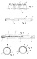
- fig. 1 exemplifies a portion of a corrugated pipe cut along its axial plane, with distributed holes through which, when the pipe is placed in the ditch, the water from the soaked soil will seep inside it;
- fig. 2 exemplifies, in a different scale, a section of a drainage pipe completely wrapped all around in a permeable strip excluding a lenght at each end;
- fig. 3 exemplifies the placing of the permeable strip on the drainage pipe, during the production process in which the sections of the drainage pipe, of the type shown in figure 2, are manufactured;
- fig. 4 is the axial front view of the drainage pipe, on a different scale, combined with the strip of filtering material which is wrapped along its entire surface;
- fig. 5 is the axial front view of the drainage pipe with the holes placed only along one portion of its surface wrapped in the filtering strip;
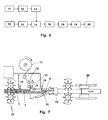
- fig. 6 is the block diagram which exemplifies the method for manufacturing the wrapped drainage pipe;
- fig. 7 exemplifies, in a schematic form, the machine which operates the
combination of the drainage pipe and the filtering strip as well as which
operates the cutting of the wrapped drainage pipe into sections, as that
shown in fig. 2.
It is understood that the drawings are exemplifying and schematic with the
sole aim of facilitating the comprehension of the invention without in any
way constituting a limitation for it.In substance the invention concerns a wrapped drainage pipe consisting in a
drainage pipe 1, normally of a corrugated type, supplied withdrainage holes 2, distributed along its length, combined with a layer of filtering material made with astrip 4 of non vegetable material, normally synthetic, or in any case a material that will not deteriorate because of humidity and air. Said combination being manufactured by wrapping thepipe 1 with thefiltering strip 4 extended in longitudinal direction, in one case by completely wrapping the pipe, with theside edges strip 4 overlapped and fixed between them by gluing or soldering, in another case by wrapping only the portion of surface of thedrainage pipe 1 where thedrainage holes 2 are distributed, with theside edges drainage pipe 1 along twodistinct lines drainage pipe 1 with thefiltering strip 4 is obtained by fixing afirst side edge 5 of the completely wrapped all around in a permeable strip excluding a lenght at each end; - fig. 3 exemplifies the placing of the permeable strip on the drainage pipe, during the production process in which the sections of the drainage pipe, of the type shown in figure 2, are manufactured;
- fig. 4 is the axial front view of the drainage pipe, on a different scale, combined with the strip of filtering material which is wrapped along its entire surface;
- fig. 5 is the axial front view of the drainage pipe with the holes placed only along one portion of its surface wrapped in the filtering strip;
- fig. 6 is the block diagram which exemplifies the method for manufacturing the wrapped drainage pipe;
- fig. 7 exemplifies, in a schematic form, the machine which operates the combination of the drainage pipe and the filtering strip as well as which operates the cutting of the wrapped drainage pipe into sections, as that shown in fig. 2.
- a stage in which a first trace of glue is laid along a
line 7 on the advancingdrainage pipe 1; - a stage in which the
filtering strip 4 is placed with itsfirst side edge 5 on said first trace of glue, along theline 7 on thedrainage pipe 1, to carry out their joining; - a stage in which a second trace of glue is laid out, in one case over said
first edge 5, in another case along asecond line 8 ofdrainage pipe 1, saidsecond line 8 placed beyond the portion equipped withdrainage holes 2; - a stage in which the
filtering strip 4 is bent around thedrainage pipe 1, till itssecond side edge 6 is brought to overlap in one case thefirst edge 5, in the second case thesecond line 8, to be joined alongedge 5, or onto the saiddrainage pipe 1.
- a stage in which
strip 4 is bent arounddrainage pipe 1 until itssecond side edge 6 is brought to overlap thefirst side edge 5; - a stage in which the two overlapped
edges
Claims (15)
- A wrapped drainage pipe, comprising a drainage pipe (1) supplied with drainage holes (2) distributed along its length and a layer of filtering material which is wrapped around it, characterised by the fact that the filtering strip (4) that wraps the drainage pipe (1) is made of non vegetable material, by the fact that said filtering strip (4) is bent over the drainage pipe (1) and extended in longitudinal direction, and by the fact that in one case the filtering strip (4) completely wraps the drainage pipe (1), with its side edges (5) and (6) overlapped and fixed between them by gluing or soldering, in another case the filtering strip (4) wraps only the portion of the surface of the drainage pipe (1) where the drainage holes (2) are distributed, with its side edges (5) and (6) not overlapped beetwen them and both fixed to the drainage pipe (1) along two distinct lines (7) and (8).
- The wrapped drainage pipe, as claimed in claim 1, characterised by the fact that the drainage pipe (1) with drainage holes (2) is wrapped in a strip (4) of filtering material, excluding at least a lenght at each of its ends.
- The wrapped drainage pipe, as claimed in claim 1, characterised by the fact that the strip (4) is made of synthetic material of a nonwoven type fabric.
- The wrapped drainage pipe, as claimed in claim 1, characterised by the fact that at least the first side edge (5) of the filtering strip (4) is fixed along a line onto the drainage pipe (1) by means of glue.
- The wrapped drainage pipe, as claimed in claim 1, characterised by the fact that the first side edge (5) of the filtering strip (4) is fixed along a line onto the drainage pipe (1) by means of hot glue.
- The wrapped drainage pipe, as claimed in claim 1, characterised by the fact that the second side edge (6) of the filtering strip (4) is overlapped onto the first edge (5) and fixed on it with glue.
- The wrapped drainage pipe, as claimed in claim 1, characterised by the fact that the second side edge (6) of the filtering strip (4) is overlapped onto the first edge (5) and fixed on it with hot glue.
- The wrapped drainage pipe, as claimed in claim 1, characterised by the fact that the second side edge (6) of the filtering strip (4) is overlapped onto the first edge (5) and fixed on it by soldering.
- The wrapped drainage pipe, as claimed in claim 1, characterised by the fact that the second side edge (6) of the filtering strip (4) is overlapped onto the first edge (5) without interruptions, for a width normally between 0,2 and 6 cm.
- The wrapped drainage pipe, as claimed in claim 1, characterised by the fact that the filtering strip (4) wraps a cylindrical section of the drainage pipe(1) on which the drainage holes (2) are placed and the side edges (5) and (6) of said strip are fixed to the said pipe by means of glue along two distinct lines (7) and (8).
- The method through which to realise the wrapped drainage pipe of claim 1, characterised by:otherwise, in absence of a second laying of glue:a stage in which at least a first trace of glue is laid along a line (7) on the forward moving drainage pipe (1) to be wrapped;a stage in which the filtering strip (4) is placed with its first side edge (5) over the first trace of glue on the drainage pipe (1) to carry out their joining;a stage in which a second trace of glue is laid, in one case over the said first side edge (5), in a second case, along a second line (8) of the drainage pipe (1);a stage in which the filtering strip (4) is bent around the drainage pipe (1) to bring its second side edge (6), in one case, to overlap and join onto the first side edge (5), in another case to overlap onto the second trace of glue along line (8);a stage in which the filtering strip (4) is bent around the drainage pipe (1) to bring its second side edge (6) to overlap onto the first side edge (5);a stage in which the two overlapped edges (5) and (6) are heated and pressed one against the other to obtain their soldering.
- The method, as claimed in claim 11, characterised by a stage in which the filtering strip (4) is cut and its forward movement is temporarily interrupted so that the drainage pipe (1) and the said filtering strip (4) may run reciprocally to create a distance between one section of wrapped drainage pipe and the next.
- The method, as claimed in claim 11, characterised by a stage in which the wrapped drainage pipe is cut in the parts where it is not combined with the filtering strip (4) to be transformed into sections.
- A machine to manufacture the drainage pipe as claimed in claim 1, characterised by the fact that it includes at least the following:a group (10) to guide and move forward the drainage pipe (1) to be wrapped;at least one group (11) for the feeding and the placing of the filtering strip (4);means (12) to cut said filtering strip (4) transversally in respect to its forward moving motion;means (14) for the laying of the first trace of glue along a line (7) of said drainage pipe (1);means (15) which lay down and press down the first side edge (5) of filtering strip (4) over the first trace of glue;means (16) for the bending of filtering strip (4) around drainage pipe (1) to wrap it;means (18) for the laying of the second trace of glue, in one case over the first side edge (5), in another case along a second line (8) of drainage pipe (1);means (19) with which the bending of filtering strip (4) over drainage pipe (1) is completed and the pressing action is also carried out, as needed, on the second side edge (6), in one case over the first side edge (5), in another case over the second trace of glue on drainage pipe (1);means (20) which grab the forward moving wrapped pipe and, in one case they accompany it in its forward movement and cut it in correspondence of the lenghts where the drainage pipe (1) is not wrapped, in another case they hold it still and cut it in correspondence of those lenghts where the drainage pipe (1) is not wrapped, then letting it go for it to move along again.
- The machine, as claimed in claim 14, characterised by the fact that it is ready to be placed on the same line as the machine which produces the drainage pipe (1) to be wrapped.
Applications Claiming Priority (2)
| Application Number | Priority Date | Filing Date | Title |
|---|---|---|---|
| ITAR20030017 | 2003-04-04 | ||
| ITAR20030017 ITAR20030017A1 (en) | 2003-04-04 | 2003-04-04 | WRAPPED TUBE FOR DRAINAGE AS WELL AS METHOD AND MACHINE |
Publications (2)
| Publication Number | Publication Date |
|---|---|
| EP1464761A2 true EP1464761A2 (en) | 2004-10-06 |
| EP1464761A3 EP1464761A3 (en) | 2007-05-16 |
Family
ID=32843878
Family Applications (1)
| Application Number | Title | Priority Date | Filing Date |
|---|---|---|---|
| EP04425164A Withdrawn EP1464761A3 (en) | 2003-04-04 | 2004-03-11 | A wrapped drainage pipe and the method and machine for its manufacture |
Country Status (3)
| Country | Link |
|---|---|
| EP (1) | EP1464761A3 (en) |
| HR (1) | HRP20040305A2 (en) |
| IT (1) | ITAR20030017A1 (en) |
Cited By (6)
| Publication number | Priority date | Publication date | Assignee | Title |
|---|---|---|---|---|
| WO2007084801A3 (en) * | 2006-01-13 | 2007-10-04 | Ring Ind Group L P | Drainage unit with external covering and method for manufacturing |
| EP3101178A1 (en) * | 2015-06-04 | 2016-12-07 | Pipelife Nederland B.V. | Method for manufacturing a drain system |
| GR1008995B (en) * | 2013-03-11 | 2017-03-28 | Εμμ. Κουβιδης Α.Β.Ε.Ε. | Three-layered drain composed of a corrugated double-structured geofabric-coated tube |
| EP3416904A4 (en) * | 2016-02-16 | 2019-11-20 | Presby Patent Trust | Modular liquid waste treatment integrated fin members, structure, assembly and method of manufacture |
| CN111775439A (en) * | 2020-07-07 | 2020-10-16 | 新疆新鲁博科技有限公司 | Pipe coating machine and method of using the same |
| CN112810099A (en) * | 2021-01-28 | 2021-05-18 | 中交第一航务工程局有限公司 | Production device and production process of hollow circular tube heating type plastic drainage plate |
Families Citing this family (1)
| Publication number | Priority date | Publication date | Assignee | Title |
|---|---|---|---|---|
| CN108127025A (en) * | 2018-01-22 | 2018-06-08 | 宁波泰茂车业有限公司 | A kind of cycle frame abnormal shape down tube automatic moulding material-preparing machine |
Family Cites Families (4)
| Publication number | Priority date | Publication date | Assignee | Title |
|---|---|---|---|---|
| US3877831A (en) * | 1972-06-13 | 1975-04-15 | Ernest J Maroschak | Method of apparatus for drilling holes in tubes |
| DE7820028U1 (en) * | 1978-07-04 | 1978-10-12 | Hoechst Ag, 6000 Frankfurt | FILTER TUBE |
| US5466092A (en) * | 1993-10-25 | 1995-11-14 | Semenza; Christopher G. | Form-drain filter |
| DE69825039T2 (en) * | 1998-06-30 | 2005-08-18 | Albert Verdonck | Sheathed drainage pipe |
-
2003
- 2003-04-04 IT ITAR20030017 patent/ITAR20030017A1/en unknown
-
2004
- 2004-03-11 EP EP04425164A patent/EP1464761A3/en not_active Withdrawn
- 2004-03-31 HR HR20040305A patent/HRP20040305A2/en not_active Application Discontinuation
Cited By (7)
| Publication number | Priority date | Publication date | Assignee | Title |
|---|---|---|---|---|
| WO2007084801A3 (en) * | 2006-01-13 | 2007-10-04 | Ring Ind Group L P | Drainage unit with external covering and method for manufacturing |
| US8256990B2 (en) | 2006-01-13 | 2012-09-04 | Ezflow, L.P. | Drainage unit with external covering and method for manufacture |
| GR1008995B (en) * | 2013-03-11 | 2017-03-28 | Εμμ. Κουβιδης Α.Β.Ε.Ε. | Three-layered drain composed of a corrugated double-structured geofabric-coated tube |
| EP3101178A1 (en) * | 2015-06-04 | 2016-12-07 | Pipelife Nederland B.V. | Method for manufacturing a drain system |
| EP3416904A4 (en) * | 2016-02-16 | 2019-11-20 | Presby Patent Trust | Modular liquid waste treatment integrated fin members, structure, assembly and method of manufacture |
| CN111775439A (en) * | 2020-07-07 | 2020-10-16 | 新疆新鲁博科技有限公司 | Pipe coating machine and method of using the same |
| CN112810099A (en) * | 2021-01-28 | 2021-05-18 | 中交第一航务工程局有限公司 | Production device and production process of hollow circular tube heating type plastic drainage plate |
Also Published As
| Publication number | Publication date |
|---|---|
| ITAR20030017A1 (en) | 2004-10-05 |
| HRP20040305A2 (en) | 2005-02-28 |
| EP1464761A3 (en) | 2007-05-16 |
Similar Documents
| Publication | Publication Date | Title |
|---|---|---|
| FI73011B (en) | FOERFARANDE FOER TILLVERKNING AV EN SOEM. | |
| CN101267730B (en) | Irrigation pipe comprising a multilayer pipe wall | |
| EP1464761A2 (en) | A wrapped drainage pipe and the method and machine for its manufacture | |
| KR100935817B1 (en) | Drain board manufacturing equipment | |
| JPH0368964B2 (en) | ||
| US4018017A (en) | Expansion joint means | |
| JPS5844200A (en) | Waterproof execution method for tunnel | |
| KR20090107178A (en) | Waterproof Structures for Tunnels | |
| JP5419137B2 (en) | Reservoir and its formation method | |
| CN207997593U (en) | A kind of rigid spiral water-permeable pipe production line | |
| WO2008079831A1 (en) | Method of application of heat-shrinkable articles | |
| KR100349475B1 (en) | A repairing tube of sewerage by non-digging type, and a process of preparing the same | |
| JP4279385B2 (en) | Method and apparatus for partial repair of pipeline and repair material used therefor | |
| JP2942253B1 (en) | Joint section gutter installation method | |
| CN217462254U (en) | Simple fixing device for tunnel longitudinal drainage pipe | |
| JP4840708B2 (en) | Pipe lining material and manufacturing method thereof | |
| KR100529195B1 (en) | Elasticized waterproofing sheet and waterproofing structure of tunnel using the same | |
| KR20050092501A (en) | Interior water proofing member of tunnel having effective draining function | |
| JP3942838B2 (en) | Tunnel waterproof sheet and its laying method | |
| KR101303628B1 (en) | Round Shape Several Bundles Drainage Pipe With Felt and Felt Packing | |
| JP2702099B2 (en) | Start liner with flange for branch pipe and pipe lining method | |
| GR1008995B (en) | Three-layered drain composed of a corrugated double-structured geofabric-coated tube | |
| KR20090085789A (en) | Tube manufacturing equipment for pipe storage | |
| KR200354460Y1 (en) | Interior water proofing member of tunnel having effective draining function | |
| KR20050108492A (en) | A tube materials used in repairing water suply pipe and drainpipe by non-excavation system |
Legal Events
| Date | Code | Title | Description |
|---|---|---|---|
| PUAI | Public reference made under article 153(3) epc to a published international application that has entered the european phase |
Free format text: ORIGINAL CODE: 0009012 |
|
| AK | Designated contracting states |
Kind code of ref document: A2 Designated state(s): AT BE BG CH CY CZ DE DK EE ES FI FR GB GR HU IE IT LI LU MC NL PL PT RO SE SI SK TR |
|
| AX | Request for extension of the european patent |
Extension state: AL LT LV MK |
|
| PUAL | Search report despatched |
Free format text: ORIGINAL CODE: 0009013 |
|
| AK | Designated contracting states |
Kind code of ref document: A3 Designated state(s): AT BE BG CH CY CZ DE DK EE ES FI FR GB GR HU IE IT LI LU MC NL PL PT RO SE SI SK TR |
|
| AX | Request for extension of the european patent |
Extension state: AL LT LV MK |
|
| 17P | Request for examination filed |
Effective date: 20071112 |
|
| AKX | Designation fees paid |
Designated state(s): AT BE BG CH CY CZ DE DK EE ES FI FR GB GR HU IE IT LI LU MC NL PL PT RO SE SI SK TR |
|
| AXX | Extension fees paid |
Extension state: AL Payment date: 20071112 |
|
| 17Q | First examination report despatched |
Effective date: 20080102 |
|
| GRAP | Despatch of communication of intention to grant a patent |
Free format text: ORIGINAL CODE: EPIDOSNIGR1 |
|
| STAA | Information on the status of an ep patent application or granted ep patent |
Free format text: STATUS: THE APPLICATION IS DEEMED TO BE WITHDRAWN |
|
| 18D | Application deemed to be withdrawn |
Effective date: 20100309 |