EP1464559A1 - Steering tilt column assembly for vehicle - Google Patents
Steering tilt column assembly for vehicle Download PDFInfo
- Publication number
- EP1464559A1 EP1464559A1 EP03007775A EP03007775A EP1464559A1 EP 1464559 A1 EP1464559 A1 EP 1464559A1 EP 03007775 A EP03007775 A EP 03007775A EP 03007775 A EP03007775 A EP 03007775A EP 1464559 A1 EP1464559 A1 EP 1464559A1
- Authority
- EP
- European Patent Office
- Prior art keywords
- bracket
- tilt
- column
- capsule
- driving gear
- Prior art date
- Legal status (The legal status is an assumption and is not a legal conclusion. Google has not performed a legal analysis and makes no representation as to the accuracy of the status listed.)
- Granted
Links
- 239000002775 capsule Substances 0.000 claims abstract description 43
- 230000001965 increasing effect Effects 0.000 claims abstract description 10
- 230000003247 decreasing effect Effects 0.000 claims abstract description 7
- 238000003780 insertion Methods 0.000 claims description 12
- 230000037431 insertion Effects 0.000 claims description 12
- 238000003825 pressing Methods 0.000 claims description 4
- 230000002708 enhancing effect Effects 0.000 claims description 3
- 230000000754 repressing effect Effects 0.000 claims 1
- 230000000630 rising effect Effects 0.000 claims 1
- 239000000463 material Substances 0.000 abstract description 10
- 230000009977 dual effect Effects 0.000 abstract description 2
- 230000000694 effects Effects 0.000 abstract description 2
- 238000010276 construction Methods 0.000 description 13
- 238000004519 manufacturing process Methods 0.000 description 7
- 238000002844 melting Methods 0.000 description 4
- 230000008018 melting Effects 0.000 description 4
- 238000010521 absorption reaction Methods 0.000 description 3
- 238000000034 method Methods 0.000 description 3
- 238000005452 bending Methods 0.000 description 2
- 229910000831 Steel Inorganic materials 0.000 description 1
- 230000002159 abnormal effect Effects 0.000 description 1
- XAGFODPZIPBFFR-UHFFFAOYSA-N aluminium Chemical compound [Al] XAGFODPZIPBFFR-UHFFFAOYSA-N 0.000 description 1
- 229910052782 aluminium Inorganic materials 0.000 description 1
- 230000015572 biosynthetic process Effects 0.000 description 1
- 238000011900 installation process Methods 0.000 description 1
- 239000007769 metal material Substances 0.000 description 1
- 238000012986 modification Methods 0.000 description 1
- 230000004048 modification Effects 0.000 description 1
- 239000010959 steel Substances 0.000 description 1
- 229920003002 synthetic resin Polymers 0.000 description 1
- 239000000057 synthetic resin Substances 0.000 description 1
Images







Classifications
-
- B—PERFORMING OPERATIONS; TRANSPORTING
- B62—LAND VEHICLES FOR TRAVELLING OTHERWISE THAN ON RAILS
- B62D—MOTOR VEHICLES; TRAILERS
- B62D1/00—Steering controls, i.e. means for initiating a change of direction of the vehicle
- B62D1/02—Steering controls, i.e. means for initiating a change of direction of the vehicle vehicle-mounted
- B62D1/16—Steering columns
- B62D1/18—Steering columns yieldable or adjustable, e.g. tiltable
- B62D1/19—Steering columns yieldable or adjustable, e.g. tiltable incorporating energy-absorbing arrangements, e.g. by being yieldable or collapsible
-
- B—PERFORMING OPERATIONS; TRANSPORTING
- B62—LAND VEHICLES FOR TRAVELLING OTHERWISE THAN ON RAILS
- B62D—MOTOR VEHICLES; TRAILERS
- B62D1/00—Steering controls, i.e. means for initiating a change of direction of the vehicle
- B62D1/02—Steering controls, i.e. means for initiating a change of direction of the vehicle vehicle-mounted
- B62D1/16—Steering columns
- B62D1/18—Steering columns yieldable or adjustable, e.g. tiltable
- B62D1/184—Mechanisms for locking columns at selected positions
-
- B—PERFORMING OPERATIONS; TRANSPORTING
- B62—LAND VEHICLES FOR TRAVELLING OTHERWISE THAN ON RAILS
- B62D—MOTOR VEHICLES; TRAILERS
- B62D1/00—Steering controls, i.e. means for initiating a change of direction of the vehicle
- B62D1/02—Steering controls, i.e. means for initiating a change of direction of the vehicle vehicle-mounted
- B62D1/16—Steering columns
- B62D1/18—Steering columns yieldable or adjustable, e.g. tiltable
- B62D1/19—Steering columns yieldable or adjustable, e.g. tiltable incorporating energy-absorbing arrangements, e.g. by being yieldable or collapsible
- B62D1/195—Yieldable supports for the steering column
Definitions
- the present invention relates to a steering tilt column assembly for a vehicle, and in particular to a steering tilt column assembly for a vehicle which is capable of implementing a stable engaged state of an engaged fixing gear and driving gear for continuing a tilting state, removing some parts by directly operating an upward rotation operation of a driving gear using a tilt lever, preventing a noise and loosening by preventing a bolt used for a lever hinge of a tilt lever from affecting to a rotation friction during a rotation of a tilt lever, increasing an impact absorbing effect and unit cost by improving a material and structure of an initial impact absorbing capsule used for a mounting bracket, and implementing an impact absorbing and fixed engagement without using a dual column by making an engaging structure of a lower portion of a column and a lower bracket have a cross sectional portion with a decreased diameter.
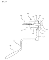
- a vehicle steering tilt column assembly is installed in an outer portion of a steering shaft 20 adapted to transfer a rotational force from a steering wheel to a gear box for thereby supporting a rotation of the same and connecting to a vehicle body.
- Figure 1 is a view illustrating a conventional steering tilt column assembly.
- a unit for connecting a steering tilt column assembly to a vehicle body includes a mounting bracket 70 fixed in an intermediate position of the column 10, a capsule 80 inserted into a slot at both sides of the mounting bracket, and a lower bracket 90 which is fixed in a lower position of the column 10 formed of an outer tube 10a and an inner tube 10b, namely, in a lower portion of the inner tube 10b.
- the steering shaft 20 includes an upper and lower ends connected with a steering wheel and a gear box, respectively, and is connected with a universal joint adapted to transfer a rotational force in a bent state therebetween.
- the steering column adapted to support the steering shaft includes a tilting apparatus adapted to maintain a bent state of the steering shaft and to adjust an angle of a steering wheel based on a driver's physical state.
- Figure 2 is a view illustrating the above tilting apparatus.
- a column bracket 30 is installed in an upper portion of the steering column 10.
- a tilt bracket 40 is installed in an outer portion at both sides of the column bracket 30 for surrounding the same.
- the column bracket 30 and the tilt bracket 40 are connected with both ends of the split steering shaft 20, respectively.
- both sides of the column bracket 30 and the tilt bracket 40 are engaged to the tilt hinge 32, respectively, and when the steering shaft 20 installed in the interior of the same is bent, the same is bent by the universal joint(not shown) based on a cooperation of the same.
- a circular shaped fixing gear 31 which as the same center as the tilt hinge 32 and a threaded portion in an outer surface of the same is installed in an outer one side of the column bracket 30.
- a driving gear 41 is formed in the tilt bracket 40 and is engaged with the fixing gear 31.
- one end of the driving gear 41 is engaged to the gear hinge 42 in the tilt bracket 40, and a threaded portion engaged with a threaded portion of the fixing gear 31 is formed in an inner surface of the front end of the same and is elastically supported by a spring(not shown) based on a continuous engagement.
- the tilt bracket 40 has a certain structure capable of rotating the driving gear 41 for angling the column bracket 30, the tilt bracket 40 and the steering shaft 20 by distancing the engaged driving gear 41 and the fixing gear 31.
- a driving pin 43 protruded in one side of the driving gear 41.
- a rotation member 50 is installed in a lower side of the driving pin 43 for thereby lifting the driving gear 41 through the driving pin 43.
- the rotation member 50 is rotatably installed by the tilt hinge 32 at its center.
- the rotation member 50 is installed between the tilt bracket 40 and the column bracket 30 in such a manner that opposite bent both ends of the same are passed through by the tilt hinge 32, and the intermediate portion of the same covers an outer surface of the driving gear 41.
- a rotation portion 51 is formed in a lower side of the driving pin 43.
- the portion in which the rotation portion 51 of the rotation member 50 is formed is connected with the gear hinge 42 which is a rotation point of the driving gear 41 and is recovered after the operation of the rotation member 50.
- a recovering spring 54 is installed so that the tilt bracket 40 and the column bracket 30 are bent and recovered to their original positions.
- Another recovering spring 55 is installed in the opposite portion of the recovering spring 54 with respect to the tilt hinge 32 so that the tilt bracket 40 and the column bracket 30 are bent to the other side and then are recovered.
- connection portion 52 which is longitudinally extended in the direction of the tilt bracket 40 and is bent is formed in the portion opposite to the rotation portion 51 of the rotation member 50.
- the above connection potion 52 is connected through an end portion of the tilt lever 60 in which an intermediate portion is rotatably fixed in the lever hinge 61 formed in the tilt bracket 40 and the connection spring 53.
- the steering tilt column assembly has an impact absorbing structure.
- a capsule 80 inserted into the mounting bracket 70, and a collapsing structure capable of implementing an impact absorbing function in the lower mounting portion.
- the steering column 10 is engaged with two hollow tubes of an outer tube 10a and an inner tube 10b for thereby contracting when an impact is transferred.
- the conventional vehicle steering column tilting apparatus has the following problems.
- the driving gear 41 may be lifted up for thereby unlocking the locked state.
- the rotation member 50 is installed between the tilt bracket and the column bracket using a tilt hinge for thereby lifting the driving gear 41.
- the rotation member is formed of a thin steel plate rotating. Therefore, the strength is weak, and the rotation member 50 may be bent when an external impact is transferred, so that a pop-up problem(steering wheel is popped up) may occur. Furthermore, the rotation member 50 may be omitted by improving the structure.
- a common bolt 61 a is engaged in the lever hinge 61 for rotatably fixing the tilt lever 60 in the tilt bracket 40.
- an intermediate portion of the same surrounds the upper side of the steering column 10, and an expanding portion 71 is formed in extended both sides and is opposite to the vehicle body.
- a slot 42 which is opened in the upper side is formed in the expanding portion 71.
- the capsule 80 is formed by injecting aluminum.
- An insertion groove 81 is formed in both sides in order for an outer surface of the slot 72 to be inserted thereinto.
- a bolt hole 82 is formed in the center, so that the bolt 84 passes through the same and is fixed to the vehicle body.
- a plurality of capsule holes 83 and slot holes 73 which pass through the upper and lower sides are formed in the engaged outer surfaces of the capsule 80 and the slot 72.
- a plastic melting material is injected in the interior of the same for thereby hardening the same and forming a pin shape.
- the hardened plastic melting material connects the capsule 80 fixed to the vehicle body and the mounting bracket 70 fixed to the steering column 10.
- the plastic melting material is broken, so that the steering column 10 is separated from the capsule 80.
- the capsule and the basic structure of the mounting bracket engaged thereto are complicated.
- a complicated process for injecting a plastic melting material and hardening the same in the slot hole communicating with the capsule hole formed in the capsule is needed. Therefore, the installation process is complicated, and the fabrication cost is increased.
- the weight managing limit is low based on the property of the material, the applicable range is limited.
- the structure may be more complicated.
- a lower bracket should be used for fixing the lower portion of the column to the vehicle body. Since the lower bracket of the lower portion of the column is integrally welded, an additional inner tube must be used for implementing an impact absorbing structure. In addition, the lower bracket must be welded to the lower portion of the inner tube.
- Figure 1 is a view illustrating the conventional impact absorbing structure.
- a collapsing problem occurs between the outer tube 10a which surrounds the steering shaft 20 and the inner tube 10b fixed to the lower bracket for thereby absorbing an impact energy when a vehicle collides.
- the inner tube 10b is fixed to the vehicle body by the lower bracket 90, and one end of the same is engaged to an inner surface of the outer tube 10a.
- a plurality of curling portions 10c are formed along an outer circumference in the inner surface of the outer tube 10a.
- the above formation of the curling potion 10c is performed in such a manner that the portions remaining piercing operations are formed in the outer tube 10a are inwardly rolled.
- the above curling portion 10c is assembled to the end portion of the inner tube 10b for thereby implementing a friction force.
- the end portion of the inner tube 10b of the lower mounting portion makes a friction with the curling portion 10c of the outer tube 10a, so that a collapsing operation is performed for thereby absorbing the impact energy.
- the curling portion 10c may be broken based on the material for thereby causing an error product.
- the process for forming the curling portion 10b in the outer tube 10a is very complicated.
- the inner tube must be added. Therefore, the number of parts is increased.
- a steering column which includes a steering shaft which includes an upper side shaft and a lower side shaft connected with a universal joint in their lower and upper ends, an upper unit which is formed of an upper side tube which includes a steering shaft and surrounds a surrounding portion of the upper side shaft, a tilt bracket connected with the upper side tube, and a shroud bracket for fixing the above elements to a vehicle body, and a lower unit which is formed of a lower side tube which surrounds a surrounding portion of the lower side shaft, a column bracket which is connected with an upper end of the lower side tube and has a capsule assembling slot in left and right wing portions, and a lower mounting bracket adapted to fix a lower end of the lower side tube to a vehicle body, wherein hinge pin holes formed in left and right sides of the tilt bracket and hinge pin holes formed in left and right sides of the column bracket are engaged using a hinge pin, so that the upper unit including the upper side shaft is bent at a certain angle about the hinge pin with respect to the lower unit including the lower side shaft,
- Figure 5 is a perspective view illustrating the whole construction of a steering tilt column assembly for a vehicle according to the present invention
- Figure 6 is a plan view illustrating the whole construction of a steering tilt column assembly for a vehicle according the present invention
- Figure 7 is a bottom view illustrating the whole construction of the present invention.
- a steering tilt column assembly includes a steering shaft 100 which is formed of an upper side shaft 101 and a lower side shaft 102 connected by a universal joint 103 in their lower and upper portions, an upper side tube 211 which includes the steering shaft 100 and surrounds the surrounding portion of the upper side shaft 101, a tilt bracket 212 connected to the upper side tube, an upper unit 210 which includes a shroud bracket 213 for fixing the above elements to a vehicle body, a lower side tube 221 which surrounds the surrounding portion of the lower side shaft 102, a column bracket 222 which has a capsule assembling slot 222b in a left and right wing portion 222a in a connected state to an upper portion of the lower side tube, and a lower unit 220 which includes a low mounting bracket 223 for fixing a lower portion of the lower side tube 221 to a vehicle body.
- a tilting operation is implemented by connecting a hinge pin hole 212b formed in left and right sides of the tilt bracket 212 and a hinge pin hole 212b formed in left and right sides of the column bracket 222 using a hinge pin 201.
- the upper unit 210 which includes the upper side shaft 101 with respect to the lower unit 220 including the lower side shaft 102 is bent at a certain angle about the hinge pin 201.
- the tilting adjusting unit 300 according to the present invention adapted to implement the above tilting operation will be described with reference to Figure 9.
- a fixing gear 310 which is fixed to an upper surface of the column bracket 222 and has a threaded potion 311 in the upper surface of the same, a driving gear 320 which has a protrusion 323 of the upper surface and is rotatable on the tilt bracket 212 and is constructed in such a manner that the threaded portion 321 of the lower surface is engaged to the threaded portion of the fixing gear, and a wedge member 330 which has a wedge portion 331 adapted to press the protrusion 323 of the driving gear 320 and a connection protrusion 332 in the lower surface of the front end.
- the fixing gear 310 is fixed in a conventional manner using an engaging bolt.
- the driving gear 320 is upwardly and downwardly rotatable by inserting the rear end of the same between the hinge support ribs 212e protruded from both sides of the upper surface of the tilt bracket 212, and the shaft pin 325 passes through in a horizontal direction.
- the guard portion 212d which is formed across both sides in the portion higher than the hinge support ribs 212e protruded for installing the driving gear is provided, so that it is possible to press the upper surface of the wedge member 330.
- the wedge member 330 and the driving gear 320 positioned in the lower portion of the guard portion 212d are operated by the tilt lever 340.
- the tilt lever 340 includes a horizontal portion 342 which has a hinge hole 343 for a rotatable engagement on the tilt bracket 212 by inserting the engaging hole 344 into which the connection protrusion 332 of the wedge member 330 is inserted and the hinge bolt 347, a handle 341 which is extended from one side end of the horizontal portion 342, an extended portion 345 extended from the other side of the horizontal portion 342, and an inclination portion 346 which is inclined for lifting the side surface protrusion 324 of the driving gear 320.
- the tilt lever 340 is engaged by the hinge bolt 347 for thereby implementing a stable rotation.
- the hinge bolt 347 which has a hinge point obtained by inserting the same into the hinge hole 343 of the horizontal portion 342 of the tilt lever 340 is engaged based on a straight line portion 347a in the lower portion of the bolt head.
- the straight line portion 347a has a diameter D larger than the diameter of the threaded portion of the bolt and a length L longer than the thickness of the horizontal portion 342 or a (+)tolerance. Therefore, when engaged using the hinge bolt 347, since the horizontal portion 342 is not pressed by the bolt head, the horizontal portion 342 does not have a friction resistance.
- the hinge bolt 347 may be implemented in another embodiment of the present invention. Namely, as shown in Figure 13, an expanding hole 222f is formed in an upper portion of the threaded hole 222a to which the hinge bolt 347 is engaged, and a part of the straight line portion 347a of the hinge bolt 347 is inserted into the expanding hole 222f.
- the length L of the straight line portion 347a is the size that the depth d of the expanding hole 222f is added with the thickness of the horizontal portion 342.
- the allowable tolerance is (+), not (-).
- a tension spring 230 is connected between the wedge member 330 and the shroud bracket 213 for pulling the wedge member 330 in one direction.
- a tension spring 230 is connected between the tilt lever 340 and the shroud bracket 213 for returning the tilt lever 340 to its original position when the same is rotated.
- an initial impact absorbing unit 400 is provided for fixing the column bracket 222 to the vehicle body.
- the capsule 410 in the initial impact absorbing unit 400, includes an upper plate 411 having a plurality of protrusions 413 in the lower surface, a lower plate 412 which has a plurality of protrusions 413 in the upper surface, and an elastic portion 414 which integrally connects one side of the upper plate and one side of the lower plate.
- the capsule 410 has a certain width W between the end surface of the support member 416a of the upper plate 411 and the end surface of the support member 416b of the lower plate 412 when the upper plate 411 and the lower plate 412 are parallel.
- the above width W is smaller than the heights of the protrusions 413 formed in the upper plate 411 and the lower plate 412.
- the width W is provided for preventing the protrusions of the upper plate 411 and the lower plate 412 from being broken due to an over engaging force of the bolt when the engaging bolt is inserted through the bolt hole 415 and is engaged to the vehicle body.
- the capsule 410 and the wing portions 222a of the column bracket 222 are not escaped from each other when an impact occurs, so that it is impossible to implement a desired impact absorbing function.
- the column bracket 222 of the present invention for using the capsule 410 includes a mounting groove 222c for mounting the capsule 410 therein in the surrounding portion of the slot 222b of the wing portion 222a, and the capsule 410 is inserted into the mounting groove 222c.
- the through holes 222d corresponding to the position of the protrusions 413 of the capsule 410 are formed in the mounting groove 222c. Therefore, it is possible to engage the capsule in a state that the protrusions 413 are in the through holes 222d as shown in Figure 17. In addition, as shown in Figure 17, the through holes 222d may not be formed.
- a lower side impact absorbing unit 500 is provided between the lower side tube 221 and the lower mounting bracket 223.
- a flat surface 221 a is formed in an end portion of the lower side tube 221 based on a decrease of the outer diameter
- the lower mounting bracket 223 has an insertion hole 223a having a straight line inner diameter portion 223b to be matched with a cross section shape of the end portion in which the flat surface of the lower side tube is formed.
- the lower mounting bracket 223 may has an inner extended portion 223c formed by extending the inner circumference of the insertion hole 223a and bending the same in a certain direction for thereby enhancing a friction force.
- the straight inner diameter portion 223b formed in the flat surface 221 a of the end portion of the lower side tube 221 and the insertion hole 223a of the low mounting bracket 223 may be provided in multiple numbers at other positions as shown in Figure 20.
- the above construction is provided for maintaining a certain gap and preventing the initial friction inertia force from being maximized.
- the reference numeral 600 represents a stopper unit for limiting the bending angles of the upper and lower directions of the tilt bracket 212.
- the upper side shaft 101 and the tilt bracket 212 and the upper unit 210 including a part of the tilting adjusting unit 300 may be upwardly rotated and lifted up about the hinge pin 201 which is a tilt hinge point or may be downwardly rotated.
- the tilt lever 340 In a state that the tilt lever 340 is pulled, when the upper unit is in a desired position by upwardly and downwardly adjusting the same, in the above state, the tilt lever 340 is placed down.
- the tilt lever 340 is returned by a force of the tilt lever returning spring 350, and when the tilt lever is returned, the horizontal portion 342 and the extended portion 345 of the other end are returned.
- the above operation is implemented in such a manner that the wedge member 330 in which the connection protrusion 332 is engaged to the engaging hole 344 of the horizontal portion 342 is pulled.
- the wedge member 330 is downwardly rotated by downwardly pressing the protrusion 323 of the upper surface of the driving gear 320 using the wedge portion 331 of the lower surface. At this time, the inclination portion 346 of the retracted extended portion 345 allows the side surface protrusion 324 of the driving gear 320 to be downwardly moved.
- the wedge member 330 returning by the spring 350 is inserted between the guard portion 212d formed in the upper portion of the tilt bracket 212 and the protrusion 323 of the upper surface of the driving gear 320. Since the wedge portion 331 of the wedge member 330 presses the protrusion 323 of the upper surface of the driving gear 320, the driving gear 320 is downwardly pressed, and the threaded portion 321 of the driving gear 320 is engaged with the threaded portion 311 of the fixing gear 310 for thereby completing a tilting adjustment.
- the initial impact absorbing unit 400 when an impact is applied in the longitudinal direction of the shaft, the initial impact absorbing unit 400 is first operated, and at the same time the impact absorbing unit 500 of the lower side of the lower side tube is operated for thereby absorbing the impact.
- the left and right wing portions 222a of the column bracket 222 are escaped from the capsule 410 fixed to the vehicle body by a bolt based on a certain friction force.
- the straight line inner diameter portion 223b of the insertion hole 223a of the lower mounting bracket 223 is force-fit into the flat surface 221a of the end portion of the lower side tube 221
- the straight line inner diameter portion 223b of the insertion hole 223a is distanced from the flat surface 221a and goes to the cylindrical portion. Therefore, since the same must overcome the change of the outer diameter and must advance, it is possible to absorb the impact.
- a wedge member adapted to press the driving gear in the upper portion of the tilt bracket and a guard portion adapted to press the wedge member it is possible to implement a stable engaged state of the fixing gear and the driving gear for continuously implementing a certain tilting state. In addition, it is possible to enhance a stability of the tilting state.
- the capsule for the initial impact absorbing unit is formed of a metallic material without using a synthetic resin material, and there is provided a structure with protrusions, it is possible to implement an easier fabrication, and the price is low, and it is possible to implement an initial impact absorption based on only the friction force between the capsule and the mounting bracket.
- an engaging structure of the lower portion of the column and the lower bracket has a cross section portion with a decreased diameter and is directly engaged to the vehicle body through the lower bracket, it is possible to implement an impact absorbing unit without an additional inner tube inserted into the lower side of the lower side tube like the conventional art.
Landscapes
- Engineering & Computer Science (AREA)
- Chemical & Material Sciences (AREA)
- Combustion & Propulsion (AREA)
- Transportation (AREA)
- Mechanical Engineering (AREA)
- Steering Controls (AREA)
Abstract
Description
- The present invention relates to a steering tilt column assembly for a vehicle, and in particular to a steering tilt column assembly for a vehicle which is capable of implementing a stable engaged state of an engaged fixing gear and driving gear for continuing a tilting state, removing some parts by directly operating an upward rotation operation of a driving gear using a tilt lever, preventing a noise and loosening by preventing a bolt used for a lever hinge of a tilt lever from affecting to a rotation friction during a rotation of a tilt lever, increasing an impact absorbing effect and unit cost by improving a material and structure of an initial impact absorbing capsule used for a mounting bracket, and implementing an impact absorbing and fixed engagement without using a dual column by making an engaging structure of a lower portion of a column and a lower bracket have a cross sectional portion with a decreased diameter.
- Generally, a vehicle steering tilt column assembly is installed in an outer portion of a
steering shaft 20 adapted to transfer a rotational force from a steering wheel to a gear box for thereby supporting a rotation of the same and connecting to a vehicle body. - Figure 1 is a view illustrating a conventional steering tilt column assembly.
- As shown in Figure 1, a unit for connecting a steering tilt column assembly to a vehicle body includes a
mounting bracket 70 fixed in an intermediate position of thecolumn 10, acapsule 80 inserted into a slot at both sides of the mounting bracket, and alower bracket 90 which is fixed in a lower position of thecolumn 10 formed of anouter tube 10a and aninner tube 10b, namely, in a lower portion of theinner tube 10b. - The
steering shaft 20 includes an upper and lower ends connected with a steering wheel and a gear box, respectively, and is connected with a universal joint adapted to transfer a rotational force in a bent state therebetween. - In addition, the steering column adapted to support the steering shaft includes a tilting apparatus adapted to maintain a bent state of the steering shaft and to adjust an angle of a steering wheel based on a driver's physical state.
- Figure 2 is a view illustrating the above tilting apparatus.
- Here, a
column bracket 30 is installed in an upper portion of thesteering column 10. Atilt bracket 40 is installed in an outer portion at both sides of thecolumn bracket 30 for surrounding the same. Thecolumn bracket 30 and thetilt bracket 40 are connected with both ends of the splitsteering shaft 20, respectively. - In addition, both sides of the
column bracket 30 and thetilt bracket 40 are engaged to thetilt hinge 32, respectively, and when thesteering shaft 20 installed in the interior of the same is bent, the same is bent by the universal joint(not shown) based on a cooperation of the same. - A circular shaped
fixing gear 31 which as the same center as the tilt hinge 32 and a threaded portion in an outer surface of the same is installed in an outer one side of thecolumn bracket 30. Adriving gear 41 is formed in thetilt bracket 40 and is engaged with thefixing gear 31. - Namely, one end of the
driving gear 41 is engaged to thegear hinge 42 in thetilt bracket 40, and a threaded portion engaged with a threaded portion of thefixing gear 31 is formed in an inner surface of the front end of the same and is elastically supported by a spring(not shown) based on a continuous engagement. - In addition, the
tilt bracket 40 has a certain structure capable of rotating thedriving gear 41 for angling thecolumn bracket 30, thetilt bracket 40 and thesteering shaft 20 by distancing the engageddriving gear 41 and thefixing gear 31. - Namely, there is provided a driving
pin 43 protruded in one side of thedriving gear 41. Arotation member 50 is installed in a lower side of the drivingpin 43 for thereby lifting thedriving gear 41 through the drivingpin 43. Therotation member 50 is rotatably installed by thetilt hinge 32 at its center. - At this time, the
rotation member 50 is installed between thetilt bracket 40 and thecolumn bracket 30 in such a manner that opposite bent both ends of the same are passed through by thetilt hinge 32, and the intermediate portion of the same covers an outer surface of thedriving gear 41. Arotation portion 51 is formed in a lower side of the drivingpin 43. - The portion in which the
rotation portion 51 of therotation member 50 is formed is connected with thegear hinge 42 which is a rotation point of thedriving gear 41 and is recovered after the operation of therotation member 50. A recoveringspring 54 is installed so that thetilt bracket 40 and thecolumn bracket 30 are bent and recovered to their original positions. - Another recovering
spring 55 is installed in the opposite portion of the recoveringspring 54 with respect to thetilt hinge 32 so that thetilt bracket 40 and thecolumn bracket 30 are bent to the other side and then are recovered. - In addition, A
connection portion 52 which is longitudinally extended in the direction of thetilt bracket 40 and is bent is formed in the portion opposite to therotation portion 51 of therotation member 50. Theabove connection potion 52 is connected through an end portion of thetilt lever 60 in which an intermediate portion is rotatably fixed in thelever hinge 61 formed in thetilt bracket 40 and theconnection spring 53. - Therefore, when pulling the handle of the
tilt lever 60, an end portion of thetilt lever 60 pushes theconnection portion 52, and therotation member 50 is rotated. Therefore, therotation portion 52 lifts up thedriving gear 41, and thedriving gear 41 and thefixing gear 31 are distanced for thereby implementing a tilting function. - The steering tilt column assembly has an impact absorbing structure.
- As one of the functions, it is directed to implementing an initial impact absorbing function. There are provided a
capsule 80 inserted into themounting bracket 70, and a collapsing structure capable of implementing an impact absorbing function in the lower mounting portion. - As shown in Figure 1, in the latter case, the
steering column 10 is engaged with two hollow tubes of anouter tube 10a and aninner tube 10b for thereby contracting when an impact is transferred. - However, the conventional vehicle steering column tilting apparatus has the following problems.
- First, since there are not any structure and apparatus for supporting the engagement of the fixing gear and the driving gear, the driving gear and the fixing gear are easily distanced when an external impact is transferred.
- Namely, in the case that an abnormal external force or vibration occurs, since there is not any member for continuously preventing by pressing the
driving gear 41 in the direction of thefixing gear 31, thedriving gear 41 may be lifted up for thereby unlocking the locked state. - Second, the
rotation member 50 is installed between the tilt bracket and the column bracket using a tilt hinge for thereby lifting thedriving gear 41. However, the rotation member is formed of a thin steel plate rotating. Therefore, the strength is weak, and therotation member 50 may be bent when an external impact is transferred, so that a pop-up problem(steering wheel is popped up) may occur. Furthermore, therotation member 50 may be omitted by improving the structure. - Third, as shown in Figure 1, in the steering column tilting apparatus, a
common bolt 61 a is engaged in thelever hinge 61 for rotatably fixing thetilt lever 60 in thetilt bracket 40. - The engagement of the
bolt 61 a will be described. As shown in Figure 4, there are needed aplate 60b, arivet 60a, abolt 61 a and alever 60. In addition, a work process such as a bolt riveting portion of a tilt bracket is needed. Therefore, the fabrication cost is increased. - In addition, since the upper surfaces of the
bolt 61a and thetilt lever 60 closely contacted, and the lower surface of thetilt lever 60 and the upper surface of thetilt bracket 40 are closely contacted, when thebolt 61a is strongly tightened, when thetilt lever 60 is rotated, a friction force is increased, so that it is difficult to handle. In addition, the bolt is too loosely tightened, a noise occurs, and thebolt 61 a is gradually loosened. - Fourth, there are problems in the
capsule 80 adapted to fix themounting bracket 70 to a vehicle body and a structure for assembling the capsule. - In the
mounting bracket 70, an intermediate portion of the same surrounds the upper side of thesteering column 10, and an expandingportion 71 is formed in extended both sides and is opposite to the vehicle body. Aslot 42 which is opened in the upper side is formed in the expandingportion 71. In addition, thecapsule 80 is formed by injecting aluminum. Aninsertion groove 81 is formed in both sides in order for an outer surface of theslot 72 to be inserted thereinto. Abolt hole 82 is formed in the center, so that thebolt 84 passes through the same and is fixed to the vehicle body. - As shown in Figure 3, a plurality of
capsule holes 83 andslot holes 73 which pass through the upper and lower sides are formed in the engaged outer surfaces of thecapsule 80 and theslot 72. A plastic melting material is injected in the interior of the same for thereby hardening the same and forming a pin shape. - Namely, the hardened plastic melting material connects the
capsule 80 fixed to the vehicle body and themounting bracket 70 fixed to thesteering column 10. When an external impact is applied to the steering column10, the plastic melting material is broken, so that thesteering column 10 is separated from thecapsule 80. - However, in the escaping apparatus of a conventional steering column, the capsule and the basic structure of the mounting bracket engaged thereto are complicated. In addition, a complicated process for injecting a plastic melting material and hardening the same in the slot hole communicating with the capsule hole formed in the capsule is needed. Therefore, the installation process is complicated, and the fabrication cost is increased.
- Furthermore, when managing the weights using a fixing pin formed of plastic, since the weight managing limit is low based on the property of the material, the applicable range is limited. In order to overcome the above problems, when the number and thickness of the fixing pin are adjusted, the structure may be more complicated.
- Fifth, there is a problem in the impact absorbing structure formed of the
steering column 10 and thelower bracket 90 adapted to support the lower portion of the steering column. - The important points of the impact absorbing structure are that a lower bracket should be used for fixing the lower portion of the column to the vehicle body. Since the lower bracket of the lower portion of the column is integrally welded, an additional inner tube must be used for implementing an impact absorbing structure. In addition, the lower bracket must be welded to the lower portion of the inner tube.
- Figure 1 is a view illustrating the conventional impact absorbing structure.
- Namely, a collapsing problem occurs between the
outer tube 10a which surrounds the steeringshaft 20 and theinner tube 10b fixed to the lower bracket for thereby absorbing an impact energy when a vehicle collides. Theinner tube 10b is fixed to the vehicle body by thelower bracket 90, and one end of the same is engaged to an inner surface of theouter tube 10a. A plurality of curling portions 10c are formed along an outer circumference in the inner surface of theouter tube 10a. - In particular, the above formation of the curling potion 10c is performed in such a manner that the portions remaining piercing operations are formed in the
outer tube 10a are inwardly rolled. The above curling portion 10c is assembled to the end portion of theinner tube 10b for thereby implementing a friction force. - Therefore, when an impact energy is applied through the steering
shaft 20 when a vehicle collides, the end portion of theinner tube 10b of the lower mounting portion makes a friction with the curling portion 10c of theouter tube 10a, so that a collapsing operation is performed for thereby absorbing the impact energy. - However, in the above structure, when the
outer tube 10a and theinner tube 10b are assembled, the curling portion 10c may be broken based on the material for thereby causing an error product. In particular, the process for forming the curlingportion 10b in theouter tube 10a is very complicated. In addition, the inner tube must be added. Therefore, the number of parts is increased. - Accordingly, it is an object of the present invention to provide a steering tilt column assembly for a vehicle which overcomes the problems encountered in the conventional art.
- It is another object of the present invention to provide a steering tilt column assembly for a vehicle which is capable of implementing a stable engagement of a fixing gear and a driving gear for obtaining a desired tilting state by providing a guard portion in an upper portion of a tilt bracket and a wedge in a lower portion of the guard portion for thereby enhancing a stability of a tilting state.
- It is further another object of the present invention to provide a steering tilt column assembly for a vehicle which is capable of removing a conventional rotation member and increasing a productivity and decreasing a fabrication cost by directly performing an upward rotation operation of a driving gear using a tilt lever and increasing a productivity and decreasing a fabrication cost.
- It is still further another object of the present invention to provide a steering tilt column assembly for a vehicle which is capable of preventing an engaging force of a bolt from affecting a rotation friction when a tilt lever is rotated by using a bolt having a step straight line portion for a bolt of a lever hinge portion of a tilt lever and preventing a noise in a tilt lever and a bolt from being loosened.
- It is still further another object of the present invention to provide a steering tilt column assembly for a vehicle which is capable of implementing an easier fabrication and lower price by improving a material and structure of an initial impact absorbing capsule used in a mounting bracket and implementing a desired impact absorption based on only friction force between the capsule and a mounting bracket.
- It is still further another object of the present invention to provide a steering tilt column assembly for a vehicle which is capable of implementing a stable engagement and a desired impact absorption when an impact is applied by providing an engaging structure of a lower portion of a column and a lower bracket having a cross section with a decreased diameter.
- To achieve the above objects, in a steering column which includes a steering shaft which includes an upper side shaft and a lower side shaft connected with a universal joint in their lower and upper ends, an upper unit which is formed of an upper side tube which includes a steering shaft and surrounds a surrounding portion of the upper side shaft, a tilt bracket connected with the upper side tube, and a shroud bracket for fixing the above elements to a vehicle body, and a lower unit which is formed of a lower side tube which surrounds a surrounding portion of the lower side shaft, a column bracket which is connected with an upper end of the lower side tube and has a capsule assembling slot in left and right wing portions, and a lower mounting bracket adapted to fix a lower end of the lower side tube to a vehicle body, wherein hinge pin holes formed in left and right sides of the tilt bracket and hinge pin holes formed in left and right sides of the column bracket are engaged using a hinge pin, so that the upper unit including the upper side shaft is bent at a certain angle about the hinge pin with respect to the lower unit including the lower side shaft, there is provided a steering tilt column assembly for a vehicle which includes a tilting adjusting unit which includes a fixing gear and a driving gear between the column bracket and the tilt bracket, the tilting adjusting unit including a fixing gear which is fixed to an upper surface of the column bracket and has a threaded portion in an upper side surface, a driving gear in which a threaded portion of a lower surface is engaged to a threaded portion of the fixing gear, and a protrusion is formed in the upper surface of the same, the driving gear being rotatable on the tilt bracket, a wedge member which has a wedge portion in a lower surface for pressing the protrusion of the driving gear and has a connection protrusion in a lower surface of the front end, a tilt lever which is formed of an engaging hole into which a connection protrusion of the wedge member is inserted, and a hinge hole which is rotatable on the tilt bracket by inserting a hinge bolt, a handle portion extended from one end of the horizontal portion, and an extended portion which is connected with the other end of the horizontal portion and has an inclination portion for lifting up a side surface protrusion of the driving gear, a spring for pulling the wedge member and the tilt lever in a certain direction, and an extension spring adapted to return the tilt lever to an original position when the tilt lever is rotated.
- The present invention will become better understood with reference to the accompanying drawings which are given only by way of illustration and thus are not limitative of the present invention, wherein;
- Figure 1 is a perspective view illustrating a conventional steering column assembly;
- Figure 2 is a perspective view illustrating a tilting structure of a conventional steering column;
- Figure 3 is a perspective view illustrating a conventional capsule and assembled state;
- Figure 4 is a cross sectional view illustrating a structure of a conventional hinge bolt;
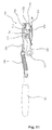
- Figure 5 is a perspective view illustrating the whole construction of a steering tilt column assembly for a vehicle according to the present invention;
- Figure 6 is a plan view illustrating the whole construction of a steering tilt column assembly for a vehicle according the present invention;
- Figure 7 is a bottom view illustrating the whole construction of the present invention;
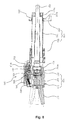
- Figure 8 is a front cross sectional view illustrating the whole construction of a steering tilt column assembly for a vehicle according to the present invention;
- Figure 9 is a disassembled perspective view illustrating the construction of major elements of a tilting adjusting unit according to the present invention;
- Figure 10 is a plan view illustrating an operation state of a tilting adjusting unit according to the present invention;
- Figure 11 is a front cross sectional view illustrating an operational state of a tilting adjusting unit according to the present invention;
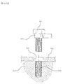
- Figure 12 is a cross sectional view illustrating a hinge portion of a tilt lever according to the present invention;
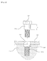
- Figure 13 is a cross sectional view illustrating a hinge portion of a tilt lever according to another embodiment of the present invention;
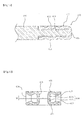
- Figure 14 is a view illustrating the construction of an initial impact absorbing unit according to the present invention;
- Figure 15 is a cross sectional view illustrating a capsule and assembled state according to the present invention;
- Figure 16 is a cross sectional view illustrating a capsule mounting groove according to another embodiment of the present invention;
- Figure 17 is a cross sectional view illustrating a capsule according to the present invention;
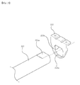
- Figure 18 is a view illustrating the construction of a lower side impact absorbing unit according to the present invention;
- Figure 19 is a cross sectional view illustrating an assembled state of a lower side impact absorbing unit according to the present invention; and
- Figure 20 is a view illustrating the construction of a lower side impact absorbing unit according to another embodiment of the present invention.
-
- The construction and operation of the present invention will be described with reference to the accompanying drawings.
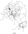
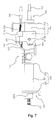
- Figure 5 is a perspective view illustrating the whole construction of a steering tilt column assembly for a vehicle according to the present invention, Figure 6 is a plan view illustrating the whole construction of a steering tilt column assembly for a vehicle according the present invention, and Figure 7 is a bottom view illustrating the whole construction of the present invention.
- As shown therein, a steering tilt column assembly according to the present invention includes a
steering shaft 100 which is formed of anupper side shaft 101 and alower side shaft 102 connected by auniversal joint 103 in their lower and upper portions, anupper side tube 211 which includes thesteering shaft 100 and surrounds the surrounding portion of theupper side shaft 101, atilt bracket 212 connected to the upper side tube, anupper unit 210 which includes ashroud bracket 213 for fixing the above elements to a vehicle body, alower side tube 221 which surrounds the surrounding portion of thelower side shaft 102, acolumn bracket 222 which has acapsule assembling slot 222b in a left andright wing portion 222a in a connected state to an upper portion of the lower side tube, and alower unit 220 which includes alow mounting bracket 223 for fixing a lower portion of thelower side tube 221 to a vehicle body. - Therefore, a tilting operation is implemented by connecting a
hinge pin hole 212b formed in left and right sides of thetilt bracket 212 and ahinge pin hole 212b formed in left and right sides of thecolumn bracket 222 using ahinge pin 201. - Namely, as shown in Figure 7, the
upper unit 210 which includes theupper side shaft 101 with respect to thelower unit 220 including thelower side shaft 102 is bent at a certain angle about thehinge pin 201. Thetilting adjusting unit 300 according to the present invention adapted to implement the above tilting operation will be described with reference to Figure 9. - There are provided a
fixing gear 310 which is fixed to an upper surface of thecolumn bracket 222 and has a threadedpotion 311 in the upper surface of the same, adriving gear 320 which has aprotrusion 323 of the upper surface and is rotatable on thetilt bracket 212 and is constructed in such a manner that the threaded portion 321 of the lower surface is engaged to the threaded portion of the fixing gear, and awedge member 330 which has awedge portion 331 adapted to press theprotrusion 323 of thedriving gear 320 and aconnection protrusion 332 in the lower surface of the front end. - At this time, the
fixing gear 310 is fixed in a conventional manner using an engaging bolt. Thedriving gear 320 is upwardly and downwardly rotatable by inserting the rear end of the same between thehinge support ribs 212e protruded from both sides of the upper surface of thetilt bracket 212, and theshaft pin 325 passes through in a horizontal direction. - In the
tilt bracket 212 according to the present invention, as an important element, theguard portion 212d which is formed across both sides in the portion higher than thehinge support ribs 212e protruded for installing the driving gear is provided, so that it is possible to press the upper surface of thewedge member 330. - The
wedge member 330 and thedriving gear 320 positioned in the lower portion of theguard portion 212d are operated by thetilt lever 340. - The
tilt lever 340 includes ahorizontal portion 342 which has ahinge hole 343 for a rotatable engagement on thetilt bracket 212 by inserting the engaginghole 344 into which theconnection protrusion 332 of thewedge member 330 is inserted and thehinge bolt 347, ahandle 341 which is extended from one side end of thehorizontal portion 342, anextended portion 345 extended from the other side of thehorizontal portion 342, and aninclination portion 346 which is inclined for lifting theside surface protrusion 324 of thedriving gear 320. - In addition, as shown in Figure 12, the
tilt lever 340 is engaged by thehinge bolt 347 for thereby implementing a stable rotation. - The
hinge bolt 347 which has a hinge point obtained by inserting the same into thehinge hole 343 of thehorizontal portion 342 of thetilt lever 340 is engaged based on astraight line portion 347a in the lower portion of the bolt head. - The
straight line portion 347a has a diameter D larger than the diameter of the threaded portion of the bolt and a length L longer than the thickness of thehorizontal portion 342 or a (+)tolerance. Therefore, when engaged using thehinge bolt 347, since thehorizontal portion 342 is not pressed by the bolt head, thehorizontal portion 342 does not have a friction resistance. - At this time, as shown in Figure 13, the
hinge bolt 347 according to the present invention may be implemented in another embodiment of the present invention. Namely, as shown in Figure 13, an expanding hole 222f is formed in an upper portion of the threadedhole 222a to which thehinge bolt 347 is engaged, and a part of thestraight line portion 347a of thehinge bolt 347 is inserted into the expanding hole 222f. At this time, the length L of thestraight line portion 347a is the size that the depth d of the expanding hole 222f is added with the thickness of thehorizontal portion 342. The allowable tolerance is (+), not (-). - In addition, the above engagement is performed for the reason that it is possible to prevent a movement of the
hinge bolt 347 and increase the engaging force. - In addition, a
tension spring 230 is connected between thewedge member 330 and theshroud bracket 213 for pulling thewedge member 330 in one direction. Atension spring 230 is connected between thetilt lever 340 and theshroud bracket 213 for returning thetilt lever 340 to its original position when the same is rotated. - In the present invention, an initial
impact absorbing unit 400 is provided for fixing thecolumn bracket 222 to the vehicle body. - Namely, as shown in Figure 14, in the initial
impact absorbing unit 400, thecapsule 410 includes anupper plate 411 having a plurality ofprotrusions 413 in the lower surface, alower plate 412 which has a plurality ofprotrusions 413 in the upper surface, and anelastic portion 414 which integrally connects one side of the upper plate and one side of the lower plate. - In addition, as shown in Figure 17, the
capsule 410 has a certain width W between the end surface of thesupport member 416a of theupper plate 411 and the end surface of thesupport member 416b of thelower plate 412 when theupper plate 411 and thelower plate 412 are parallel. The above width W is smaller than the heights of theprotrusions 413 formed in theupper plate 411 and thelower plate 412. - The width W is provided for preventing the protrusions of the
upper plate 411 and thelower plate 412 from being broken due to an over engaging force of the bolt when the engaging bolt is inserted through thebolt hole 415 and is engaged to the vehicle body. - If the
protrusions 413 of theupper plate 411 and thelower plate 412 are all broken and are engaged due to an over engaging force of the engaging bolt, thecapsule 410 and thewing portions 222a of thecolumn bracket 222 are not escaped from each other when an impact occurs, so that it is impossible to implement a desired impact absorbing function. - In addition, as shown in Figure 14, the
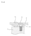
column bracket 222 of the present invention for using thecapsule 410 includes a mountinggroove 222c for mounting thecapsule 410 therein in the surrounding portion of theslot 222b of thewing portion 222a, and thecapsule 410 is inserted into the mountinggroove 222c. - As show in Figure 15, the through
holes 222d corresponding to the position of theprotrusions 413 of thecapsule 410 are formed in the mountinggroove 222c. Therefore, it is possible to engage the capsule in a state that theprotrusions 413 are in the throughholes 222d as shown in Figure 17. In addition, as shown in Figure 17, the throughholes 222d may not be formed. - In the present invention, a lower side
impact absorbing unit 500 is provided between thelower side tube 221 and thelower mounting bracket 223. - As shown in Figure 18, a
flat surface 221 a is formed in an end portion of thelower side tube 221 based on a decrease of the outer diameter, and thelower mounting bracket 223 has aninsertion hole 223a having a straight lineinner diameter portion 223b to be matched with a cross section shape of the end portion in which the flat surface of the lower side tube is formed. - Therefore, when an impact occurs in the longitudinal direction of the column, the straight line
inner diameter portion 223b of theinsertion hole 223a goes into the cylindrical portion after theflat surface 221 a. In this state, a friction force is increased for thereby absorbing the impact based on the friction force. - At this time, as shown in Figure 19, the
lower mounting bracket 223 may has an inner extended portion 223c formed by extending the inner circumference of theinsertion hole 223a and bending the same in a certain direction for thereby enhancing a friction force. - In addition, The straight
inner diameter portion 223b formed in theflat surface 221 a of the end portion of thelower side tube 221 and theinsertion hole 223a of thelow mounting bracket 223 may be provided in multiple numbers at other positions as shown in Figure 20. - The above construction is provided for maintaining a certain gap and preventing the initial friction inertia force from being maximized.
- In Figure 5, the
reference numeral 600 represents a stopper unit for limiting the bending angles of the upper and lower directions of thetilt bracket 212. - The operations and operation states of the present invention will be described.
- First, when adjusting the angle of the steering wheel by a driver, the
handle 341 of thetilt lever 340 is pulled. - When the
horizontal portion 342 of thetilt lever 340 is rotated about thehinge bolt 347, theinclination portion 346 formed in theextended portion 345 of the other side end pushes upwardly theside surface protrusion 324 protruded from the side of thedriving gear 320 and pulls thewedge member 330 engaged with theprotrusion 332 connected with the engaginghole 344 of thehorizontal portion 342. - Therefore, since the
lower surface wedge 331 of thewedge member 330 is distanced from theprotrusion 323 of the upper surface of thedriving gear 320, thedriving gear 320 is lifted up, and the threaded portion 321 of thedriving gear 320 which is lifted up is distanced from the threadedportion 311 of thefixing gear 310. - When the threaded
portion 311 of thefixing gear 310 is distanced from the threaded portion 321 of thedriving gear 320, as shown in Figure 7, theupper side shaft 101 and thetilt bracket 212 and theupper unit 210 including a part of thetilting adjusting unit 300 may be upwardly rotated and lifted up about thehinge pin 201 which is a tilt hinge point or may be downwardly rotated. - In a state that the
tilt lever 340 is pulled, when the upper unit is in a desired position by upwardly and downwardly adjusting the same, in the above state, thetilt lever 340 is placed down. - At the moment when the
tilt lever 340 is placed down, thetilt lever 340 is returned by a force of the tiltlever returning spring 350, and when the tilt lever is returned, thehorizontal portion 342 and theextended portion 345 of the other end are returned. In addition, the above operation is implemented in such a manner that thewedge member 330 in which theconnection protrusion 332 is engaged to the engaginghole 344 of thehorizontal portion 342 is pulled. - The
wedge member 330 is downwardly rotated by downwardly pressing theprotrusion 323 of the upper surface of thedriving gear 320 using thewedge portion 331 of the lower surface. At this time, theinclination portion 346 of the retractedextended portion 345 allows theside surface protrusion 324 of thedriving gear 320 to be downwardly moved. - Therefore, the
wedge member 330 returning by thespring 350 is inserted between theguard portion 212d formed in the upper portion of thetilt bracket 212 and theprotrusion 323 of the upper surface of thedriving gear 320. Since thewedge portion 331 of thewedge member 330 presses theprotrusion 323 of the upper surface of thedriving gear 320, thedriving gear 320 is downwardly pressed, and the threaded portion 321 of thedriving gear 320 is engaged with the threadedportion 311 of thefixing gear 310 for thereby completing a tilting adjustment. - In the steering tilt assembly according to the present invention, when an impact is applied in the longitudinal direction of the shaft, the initial
impact absorbing unit 400 is first operated, and at the same time theimpact absorbing unit 500 of the lower side of the lower side tube is operated for thereby absorbing the impact. - First, in the initial
impact absorbing unit 400, the left andright wing portions 222a of thecolumn bracket 222 are escaped from thecapsule 410 fixed to the vehicle body by a bolt based on a certain friction force. - Namely, since the
protrusions 413 inwardly protruded from theupper plate 411 and thelower plate 412 of thecapsule 410 are engaged before the same are fully pressed, the impact is absorbed based on a friction force of the protrusions. As shown in Figure 15, in the case that a part of eachprotrusion 413 is inserted into the throughhole 222d, since a friction force is larger, the initial impact absorbing force is large. - In addition, in the lower side
impact absorbing unit 500, in a state that the straight lineinner diameter portion 223b of theinsertion hole 223a of thelower mounting bracket 223 is force-fit into theflat surface 221a of the end portion of thelower side tube 221, when an impact occurs, the straight lineinner diameter portion 223b of theinsertion hole 223a is distanced from theflat surface 221a and goes to the cylindrical portion. Therefore, since the same must overcome the change of the outer diameter and must advance, it is possible to absorb the impact. - As described above, in the present invention, since there are provided a wedge member adapted to press the driving gear in the upper portion of the tilt bracket and a guard portion adapted to press the wedge member, it is possible to implement a stable engaged state of the fixing gear and the driving gear for continuously implementing a certain tilting state. In addition, it is possible to enhance a stability of the tilting state.
- In addition, in the present invention, since the upward rotation of the driving gear is directly operated by the tilt lever, it is possible to remove the part of the conventional rotation member. Therefore, it is possible to enhance the productivity and decrease the fabrication cost.
- In addition, when rotatably engaging the tilt lever, since as the lever hinge bolt, the bolt having a straight line portion is used, the engaging force of the bolt does not affect the rotation friction of the horizontal portion when the tilt lever is rotated. Therefore, it is possible to prevent a noise in the tilt lever and prevent a bolt from being loosened.
- In addition, since the capsule for the initial impact absorbing unit is formed of a metallic material without using a synthetic resin material, and there is provided a structure with protrusions, it is possible to implement an easier fabrication, and the price is low, and it is possible to implement an initial impact absorption based on only the friction force between the capsule and the mounting bracket.
- In addition, since an engaging structure of the lower portion of the column and the lower bracket has a cross section portion with a decreased diameter and is directly engaged to the vehicle body through the lower bracket, it is possible to implement an impact absorbing unit without an additional inner tube inserted into the lower side of the lower side tube like the conventional art.
- As the present invention may be embodied in several forms without departing from the spirit or essential characteristics thereof, it should also be understood that the above-described examples are not limited by any of the details of the foregoing description, unless otherwise specified, but rather should be construed broadly within its spirit and scope as defined in the appended claims, and therefore all changes and modifications that fall within the meets and bounds of the claims, or equivalences of such meets and bounds are therefore intended to be embraced by the appended claims.
| <Descriptions of reference numerals of major elements of the drawings> | |
| 100: steering shaft | 101: upper side shaft |
| 102: lower side shaft | 103: universal joint |
| 200: steering column | 201: hinge pin |
| 210: upper unit | 211: upper side tube |
| 212: tilt bracket | 213: shroud bracket |
| 220: lower unit | 221: lower side tube |
| 222: column bracket | 223: lower mounting bracket |
| 230: tension spring | 300: tilting adjusting unit |
| 310: fixing gear | 311: threaded portion |
| 320: driving gear | 321: threaded portion |
| 323: protrusion | 324: side surface protrusion |
| 325: shaft pin | 330: wedge member |
| 331: wedge portion | 332: connection protrusion |
| 340: tilt lever | 341: handle |
| 342: horizontal portion | 343: lever hinge hole |
| 344: engaging hole | 345: extended portion |
| 346: inclination portion | 347: hinge bolt |
| 350: spring | 400: initial impact absorbing unit |
| 410: capsule | 411: upper plate |
| 412: lower plate | 413: protrusion |
| 414: electric portion | 415: bolt hole |
| 500: lower side impact absorbing unit |
Claims (10)
- In a steering column which comprise:a steering shaft which includes an upper side shaft and a lower side shaft connected with a universal joint in their lower and upper ends;an upper unit which is formed of an upper side tube which has a steering shaft inside and surrounds a surrounding portion of the upper side shaft, a tilt bracket connected with the upper side tube, and a shroud bracket for fixing the above elements to a vehicle body;a lower unit which is formed of a lower side tube which surrounds a surrounding portion of the lower side shaft, a column bracket which is connected with an upper end of the lower side tube and has a capsule assembling slot in left and right wing portions, and a lower mounting bracket adapted to fix a lower end of the lower side tube to a vehicle body, wherein hinge pin holes formed in left and right sides of the tilt bracket and hinge pin holes formed in left and right sides of the column bracket are engaged using a hinge pin, so that the upper unit including the upper side shaft is bent at a certain angle about the hinge pin with respect to the lower unit including the lower side shaft, a vehicle steering tilt column assembly, comprising:a tilting adjusting means which includes a fixing gear and a driving gear between the column bracket and the tilt bracket;said tilting adjusting means including:a fixing gear which is fixed to an upper surface of the column bracket and has a threaded portion in an upper side surface;a driving gear in which a threaded portion of a lower surface is engaged to a threaded portion of the fixing gear, and a protrusion is formed in the upper surface of the same, said driving gear being rotatable on the tilt bracket;a wedge member which has a wedge portion in a lower surface for pressing the protrusion of the driving gear and has a connection protrusion in a lower surface of the front end;a tilt lever which is formed of a horizontal portion having an engaging hole into which a connection protrusion of the wedge member is inserted and a hinge hole which is rotatable on the tilt bracket by inserting a hinge bolt, a handle portion extended from one end of the horizontal portion, and an extended portion which is connected with the other end of the horizontal portion and has an inclination portion for lifting up a side surface protrusion of the driving gear;a spring for pulling the wedge member and the tilt lever in a certain direction; andan extension spring adapted to return the tilt lever to an original position when the tilt lever is rotated.
- The assembly of claim 1, wherein said tilt bracket includes a guard portion of a horizontal direction for repressing a rising of the wedge member in the upper side of the same.
- The assembly of claim 1, wherein the hinge bolt which is coupled by inserting the same into a hinge hole of the tilt lever and has a length L larger than the thickness of the horizontal portion of the tilt lever and a diameter D larger than the screw portion of the same is formed for thereby preventing a friction resistance with respect to the rotation of the tilt lever.
- The assembly of claim 1, wherein said column bracket includes an initial impact absorbing means in such a manner that the capsule is inserted into the slot of the wing portion formed in left and right sides and is engaged to a vehicle body, wherein said capsule includes an upper plate having a plurality of protrusions in a lower surface of the same, a lower plate having a plurality of protrusions in an upper surface of the same, and an elastic portion which integrally connects one side of the upper plate and one side of the lower plate.
- The assembly of claim 4, wherein said column bracket includes a mounting groove for mounting the capsule therein in a surrounding portion of the slot, and through holes corresponding to the positions of the protrusions of the capsule are formed in the mounting groove.
- The assembly of claim 4, wherein said capsule has an elliptical bolt hole in a center portion of the upper plate of the same for thereby forming an upper side support member in such a manner that an inner circumferential portion of the bolt hole is downwardly extended and has an elliptical bolt hole in a center portion of the lower plate of the same for thereby forming a lower side support member in such a manner that an inner circumferential portion of the bolt hole is upwardly extended, so that the upper plate and the lower plate are spaced apart by a certain distance by the upper and lower side support members.
- The assembly of claim 6, wherein an end portion of the support member of the upper plate of the capsule and an end portion of the support member of the lower plate of the capsule has a certain width W therebetween which is not larger than the height h of the protrusions formed in the upper plate and the lower plate when the upper plate and the lower plate are in parallel each other.
- The assembly of claim 1, wherein an impact absorbing means is provided between the lower side tube and the lower mounting bracket, and the lower side tube is formed in an integral shape and has an end portion of which an outer diameter is gradually decreased for thereby forming a flat surface therein, and the lower mounting bracket has an insertion hole having a straight line inner diameter portion for thereby matching with a cross section of the end portion of the flat surface of the lower side tube, so that in a state that the above matching elements are assembled each other, the straight line inner diameter portion of the insertion hole is escaped from the flat surface when an impact occurs for thereby increasing a friction force and absorbing the impact.
- The assembly of claim 8, wherein the flat surface of the end portion of the lower side tube and said straight line inner diameter portions formed in the insertion hole of the lower mounting bracket have corresponding positions each other and are formed in multiple numbers, respectively.
- The assembly of claim 8, wherein said lower mounting bracket has an insertion hole, and an inner extended portion is extended from one side of the inner circumferential portion of the insertion hole for thereby enhancing a friction force.
Priority Applications (2)
| Application Number | Priority Date | Filing Date | Title |
|---|---|---|---|
| EP20030007775 EP1464559B1 (en) | 2003-04-04 | 2003-04-04 | Steering tilt column assembly for vehicle |
| DE2003601385 DE60301385T2 (en) | 2003-04-04 | 2003-04-04 | Pivoting steering column for a vehicle |
Applications Claiming Priority (1)
| Application Number | Priority Date | Filing Date | Title |
|---|---|---|---|
| EP20030007775 EP1464559B1 (en) | 2003-04-04 | 2003-04-04 | Steering tilt column assembly for vehicle |
Publications (2)
| Publication Number | Publication Date |
|---|---|
| EP1464559A1 true EP1464559A1 (en) | 2004-10-06 |
| EP1464559B1 EP1464559B1 (en) | 2005-08-24 |
Family
ID=32842773
Family Applications (1)
| Application Number | Title | Priority Date | Filing Date |
|---|---|---|---|
| EP20030007775 Expired - Lifetime EP1464559B1 (en) | 2003-04-04 | 2003-04-04 | Steering tilt column assembly for vehicle |
Country Status (2)
| Country | Link |
|---|---|
| EP (1) | EP1464559B1 (en) |
| DE (1) | DE60301385T2 (en) |
Cited By (3)
| Publication number | Priority date | Publication date | Assignee | Title |
|---|---|---|---|---|
| RU2309866C1 (en) * | 2006-06-19 | 2007-11-10 | Открытое акционерное общество "ГАЗ" (ОАО "ГАЗ") | Locking mechanism of adjustable steering column |
| CN110962915A (en) * | 2018-09-28 | 2020-04-07 | 蒂森克虏伯普利斯坦股份公司 | Adjustable steering column assembly |
| CN113247080A (en) * | 2020-02-07 | 2021-08-13 | 操纵技术Ip控股公司 | Injection molded tilt rod assembly |
Families Citing this family (1)
| Publication number | Priority date | Publication date | Assignee | Title |
|---|---|---|---|---|
| KR101987154B1 (en) * | 2013-04-18 | 2019-06-10 | 현대자동차 주식회사 | Steering system of automobile |
Citations (4)
| Publication number | Priority date | Publication date | Assignee | Title |
|---|---|---|---|---|
| US5144855A (en) * | 1990-08-16 | 1992-09-08 | Nsk Ltd. | Tilting type steering apparatus |
| GB2312272A (en) * | 1996-04-18 | 1997-10-22 | Nastech Europ Ltd | Adjustable steering column assembly for a vehicle |
| US6282977B1 (en) * | 1997-10-28 | 2001-09-04 | Nsk Ltd. | Tilt adjusting-type steering apparatus |
| US20020020244A1 (en) * | 2000-04-24 | 2002-02-21 | Janeczko William J. | Fine increment tilt mechanism |
-
2003
- 2003-04-04 EP EP20030007775 patent/EP1464559B1/en not_active Expired - Lifetime
- 2003-04-04 DE DE2003601385 patent/DE60301385T2/en not_active Expired - Lifetime
Patent Citations (4)
| Publication number | Priority date | Publication date | Assignee | Title |
|---|---|---|---|---|
| US5144855A (en) * | 1990-08-16 | 1992-09-08 | Nsk Ltd. | Tilting type steering apparatus |
| GB2312272A (en) * | 1996-04-18 | 1997-10-22 | Nastech Europ Ltd | Adjustable steering column assembly for a vehicle |
| US6282977B1 (en) * | 1997-10-28 | 2001-09-04 | Nsk Ltd. | Tilt adjusting-type steering apparatus |
| US20020020244A1 (en) * | 2000-04-24 | 2002-02-21 | Janeczko William J. | Fine increment tilt mechanism |
Cited By (3)
| Publication number | Priority date | Publication date | Assignee | Title |
|---|---|---|---|---|
| RU2309866C1 (en) * | 2006-06-19 | 2007-11-10 | Открытое акционерное общество "ГАЗ" (ОАО "ГАЗ") | Locking mechanism of adjustable steering column |
| CN110962915A (en) * | 2018-09-28 | 2020-04-07 | 蒂森克虏伯普利斯坦股份公司 | Adjustable steering column assembly |
| CN113247080A (en) * | 2020-02-07 | 2021-08-13 | 操纵技术Ip控股公司 | Injection molded tilt rod assembly |
Also Published As
| Publication number | Publication date |
|---|---|
| DE60301385T2 (en) | 2006-06-08 |
| EP1464559B1 (en) | 2005-08-24 |
| DE60301385D1 (en) | 2005-09-29 |
Similar Documents
| Publication | Publication Date | Title |
|---|---|---|
| CN105026243B (en) | Telescopic steering apparatus and column jacket | |
| US6851712B2 (en) | Steering tilt column assembly for vehicle | |
| US20120187669A1 (en) | Steering column support apparatus | |
| JP5070795B2 (en) | Steering wheel position adjustment device | |
| CN101200195B (en) | Steering column device | |
| US8601901B2 (en) | Telescopic steering column apparatus | |
| US6523432B1 (en) | Shock-absorbing steering assembly | |
| US20150101444A1 (en) | Position adjustable steering device | |
| US7367589B2 (en) | Collapsible steering assembly with a stationary reaction surface | |
| CN103608240B (en) | Shock Absorbing Steering | |
| CN107074267B (en) | Shock Absorbing Steering | |
| CN102164803A (en) | Steering device | |
| CN107614355A (en) | Steering device | |
| EP1518775B1 (en) | Shock absorbing steering column device for vehicle | |
| EP1550598B1 (en) | Steering column device | |
| EP1464559B1 (en) | Steering tilt column assembly for vehicle | |
| JPH09272448A (en) | Shock absorption type steering column device | |
| JP3389767B2 (en) | Shock absorbing steering column device | |
| US20050268739A1 (en) | Steering column device | |
| US7077434B2 (en) | Impact absorption structure of a steering column cover for a vehicle | |
| EP3439942B1 (en) | A steering column assembly | |
| JP3715633B2 (en) | Automotive steering tilt column assembly | |
| CN105984483A (en) | Device for preventing steering column from passive washboarding and passive washboarding preventing method | |
| JP5034548B2 (en) | Steering column device | |
| KR100546511B1 (en) | Automotive Steering Tilt Column Assembly |
Legal Events
| Date | Code | Title | Description |
|---|---|---|---|
| PUAI | Public reference made under article 153(3) epc to a published international application that has entered the european phase |
Free format text: ORIGINAL CODE: 0009012 |
|
| 17P | Request for examination filed |
Effective date: 20031208 |
|
| AK | Designated contracting states |
Kind code of ref document: A1 Designated state(s): AT BE BG CH CY CZ DE DK EE ES FI FR GB GR HU IE IT LI LU MC NL PT RO SE SI SK TR |
|
| AX | Request for extension of the european patent |
Extension state: AL LT LV MK |
|
| GRAP | Despatch of communication of intention to grant a patent |
Free format text: ORIGINAL CODE: EPIDOSNIGR1 |
|
| GRAS | Grant fee paid |
Free format text: ORIGINAL CODE: EPIDOSNIGR3 |
|
| AKX | Designation fees paid |
Designated state(s): DE FR GB IT |
|
| GRAA | (expected) grant |
Free format text: ORIGINAL CODE: 0009210 |
|
| AK | Designated contracting states |
Kind code of ref document: B1 Designated state(s): DE FR GB IT |
|
| RBV | Designated contracting states (corrected) |
Designated state(s): DE FR GB IT |
|
| REG | Reference to a national code |
Ref country code: GB Ref legal event code: FG4D |
|
| REF | Corresponds to: |
Ref document number: 60301385 Country of ref document: DE Date of ref document: 20050929 Kind code of ref document: P |
|
| ET | Fr: translation filed | ||
| PLBE | No opposition filed within time limit |
Free format text: ORIGINAL CODE: 0009261 |
|
| STAA | Information on the status of an ep patent application or granted ep patent |
Free format text: STATUS: NO OPPOSITION FILED WITHIN TIME LIMIT |
|
| 26N | No opposition filed |
Effective date: 20060526 |
|
| REG | Reference to a national code |
Ref country code: FR Ref legal event code: PLFP Year of fee payment: 14 |
|
| REG | Reference to a national code |
Ref country code: FR Ref legal event code: PLFP Year of fee payment: 15 |
|
| REG | Reference to a national code |
Ref country code: FR Ref legal event code: PLFP Year of fee payment: 16 |
|
| PGFP | Annual fee paid to national office [announced via postgrant information from national office to epo] |
Ref country code: GB Payment date: 20190221 Year of fee payment: 17 |
|
| PGFP | Annual fee paid to national office [announced via postgrant information from national office to epo] |
Ref country code: FR Payment date: 20190225 Year of fee payment: 17 |
|
| PGFP | Annual fee paid to national office [announced via postgrant information from national office to epo] |
Ref country code: IT Payment date: 20190410 Year of fee payment: 17 Ref country code: DE Payment date: 20190220 Year of fee payment: 17 |
|
| REG | Reference to a national code |
Ref country code: DE Ref legal event code: R119 Ref document number: 60301385 Country of ref document: DE |
|
| PG25 | Lapsed in a contracting state [announced via postgrant information from national office to epo] |
Ref country code: FR Free format text: LAPSE BECAUSE OF NON-PAYMENT OF DUE FEES Effective date: 20200430 Ref country code: DE Free format text: LAPSE BECAUSE OF NON-PAYMENT OF DUE FEES Effective date: 20201103 |
|
| GBPC | Gb: european patent ceased through non-payment of renewal fee |
Effective date: 20200404 |
|
| PG25 | Lapsed in a contracting state [announced via postgrant information from national office to epo] |
Ref country code: GB Free format text: LAPSE BECAUSE OF NON-PAYMENT OF DUE FEES Effective date: 20200404 |
|
| PG25 | Lapsed in a contracting state [announced via postgrant information from national office to epo] |
Ref country code: IT Free format text: LAPSE BECAUSE OF NON-PAYMENT OF DUE FEES Effective date: 20200404 |