EP1464504A1 - Laser scanning apparatus - Google Patents
Laser scanning apparatus Download PDFInfo
- Publication number
- EP1464504A1 EP1464504A1 EP04006562A EP04006562A EP1464504A1 EP 1464504 A1 EP1464504 A1 EP 1464504A1 EP 04006562 A EP04006562 A EP 04006562A EP 04006562 A EP04006562 A EP 04006562A EP 1464504 A1 EP1464504 A1 EP 1464504A1
- Authority
- EP
- European Patent Office
- Prior art keywords
- scanning apparatus
- laser scanning
- laser
- cover member
- conductive
- Prior art date
- Legal status (The legal status is an assumption and is not a legal conclusion. Google has not performed a legal analysis and makes no representation as to the accuracy of the status listed.)
- Granted
Links
- 230000003287 optical effect Effects 0.000 claims abstract description 13
- 238000003384 imaging method Methods 0.000 claims abstract description 10
- 229910052751 metal Inorganic materials 0.000 claims description 52
- 239000002184 metal Substances 0.000 claims description 52
- 230000005855 radiation Effects 0.000 claims description 18
- 238000003780 insertion Methods 0.000 description 13
- 230000037431 insertion Effects 0.000 description 13
- 239000011295 pitch Substances 0.000 description 6
- 239000011347 resin Substances 0.000 description 5
- 229920005989 resin Polymers 0.000 description 5
- 230000000694 effects Effects 0.000 description 4
- 238000000034 method Methods 0.000 description 4
- 239000000758 substrate Substances 0.000 description 4
- 229910000831 Steel Inorganic materials 0.000 description 3
- 239000000463 material Substances 0.000 description 3
- 238000010008 shearing Methods 0.000 description 3
- 239000010959 steel Substances 0.000 description 3
- 239000007769 metal material Substances 0.000 description 2
- 230000004048 modification Effects 0.000 description 2
- 238000012986 modification Methods 0.000 description 2
- 230000008569 process Effects 0.000 description 2
- 230000009467 reduction Effects 0.000 description 2
- 229910000859 α-Fe Inorganic materials 0.000 description 2
- 239000003082 abrasive agent Substances 0.000 description 1
- 230000009471 action Effects 0.000 description 1
- 239000000853 adhesive Substances 0.000 description 1
- 230000001070 adhesive effect Effects 0.000 description 1
- 229910052782 aluminium Inorganic materials 0.000 description 1
- XAGFODPZIPBFFR-UHFFFAOYSA-N aluminium Chemical compound [Al] XAGFODPZIPBFFR-UHFFFAOYSA-N 0.000 description 1
- 230000008901 benefit Effects 0.000 description 1
- 230000010485 coping Effects 0.000 description 1
- 238000013461 design Methods 0.000 description 1
- 230000002542 deteriorative effect Effects 0.000 description 1
- 238000011161 development Methods 0.000 description 1
- 239000000428 dust Substances 0.000 description 1
- 230000001771 impaired effect Effects 0.000 description 1
- 238000012423 maintenance Methods 0.000 description 1
- 230000007257 malfunction Effects 0.000 description 1
- 230000007246 mechanism Effects 0.000 description 1
- 230000002093 peripheral effect Effects 0.000 description 1
- 238000004064 recycling Methods 0.000 description 1
- 230000003014 reinforcing effect Effects 0.000 description 1
- 238000000926 separation method Methods 0.000 description 1
Images




Classifications
-
- B—PERFORMING OPERATIONS; TRANSPORTING
- B41—PRINTING; LINING MACHINES; TYPEWRITERS; STAMPS
- B41J—TYPEWRITERS; SELECTIVE PRINTING MECHANISMS, i.e. MECHANISMS PRINTING OTHERWISE THAN FROM A FORME; CORRECTION OF TYPOGRAPHICAL ERRORS
- B41J2/00—Typewriters or selective printing mechanisms characterised by the printing or marking process for which they are designed
- B41J2/435—Typewriters or selective printing mechanisms characterised by the printing or marking process for which they are designed characterised by selective application of radiation to a printing material or impression-transfer material
- B41J2/47—Typewriters or selective printing mechanisms characterised by the printing or marking process for which they are designed characterised by selective application of radiation to a printing material or impression-transfer material using the combination of scanning and modulation of light
- B41J2/471—Typewriters or selective printing mechanisms characterised by the printing or marking process for which they are designed characterised by selective application of radiation to a printing material or impression-transfer material using the combination of scanning and modulation of light using dot sequential main scanning by means of a light deflector, e.g. a rotating polygonal mirror
Definitions
- the present invention relates to a laser scanning apparatus suitably used in an image forming apparatus adopting an electrophotographic process, such as a copying machine or a printer.
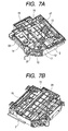
- Figs. 7A and 7B show an example of a structure of a laser scanning apparatus used in an image forming apparatus such as a copying machine or a printer.
- Figs. 7A and 7B are perspective views of the same laser scanning apparatus as viewed from an upper side and a lower side, respectively.
- Fig. 7A laser beams outgoing from a laser device 10 as a light source pass through a collimator lens 11 to be converted into parallel beams.
- the parallel beams are converted into band-shaped beams extending in a main-scanning direction by a cylindrical lens 12.
- the beams are reflected by a first folding mirror 13 and then deflected by a (rotary) polygon mirror 14.
- the beams are caused to pass through f ⁇ lenses 15 and 16, then reflected to bend toward a lower surface of the apparatus by a second folding mirror 17, and focused into an image on a photosensitive drum (not shown) through a third folding mirror 18, a toric lens 19, and a fourth folding mirror 20.
- the f ⁇ lenses 15 and 16, the second folding mirror 17, the third folding mirror 18, the toric lens 19, and the fourth folding mirror 20 constitute an imaging optical system for focusing the laser beam into an image on the photosensitive drum.
- a photosensitive drum surface is scanned with the laser beam at a constant speed by the action of the f ⁇ lenses 15 and 16.
- Those parts are mounted to a scanner case 2.
- any side of the scanner case 2 is widely opened, to which optical parts or components such as a polygon motor are incorporated.
- the parts are mounted thereto, after which the open side is covered with a cover member to keep the inside of the laser scanning apparatus airtight.
- the cover members should be provided on both the sides of the scanning apparatus.
- Fig. 8 shows an upper cover 3 and a lower cover 4 corresponding to both the open sides of the laser scanning apparatus of Figs. 7A and 7B.
- a resin material or a metal material such as a steel plate can be generally used.
- the cover member is large to some extent, the member made of the resin material easily deforms such as warping and hardly ensures the strength. Therefore, in many cases, the member is formed of the metal material such as a steel plate.
- the steel plate is a relatively low-cost material.
- the laser scanning apparatus using the metal cover member has, of course, an advantage in that part accuracy such as flatness, a strength, etc. can be secured with ease and the cost is relatively low. On the other hand, however, the following problems are entailed.
- the cover member may serve as an antenna for radiation noise generated from the laser scanning apparatus itself, for example, a drive substrate of a laser driver 21, a polygon motor driver 22, a BD sensor (not shown), etc. and a wire harness extending from the substrate or for radiation noise generated from an image forming apparatus main body to further amplify the noise, thereby affecting the image forming apparatus itself or peripheral electric devices, for example, causing a malfunction. From the very beginning, in the case of not attenuating the radiation noise, it is difficult to meet the standards for the radiation noise in countries, which are stipulated for the image forming apparatus.
- Japanese Patent Application Laid-Open No. H9-236770 discloses an example of a measure to solve the foregoing problem of the radiation noise generated when the metal cover of the laser scanning apparatus is not well grounded.
- Proposed in Japanese Patent Application Laid-Open No. H9-236770 is a laser scanning apparatus equipped with a polygon motor, a scanner case, an imaging optical system, and a metal cover, in which part of the cover member is grounded through a support part of the scanner case, and a ferrite core is further provided to the support part of the scanner case for reducing the radiation noise.
- ground wires are connected to the upper and lower covers to ground the covers to the frame etc. of the image forming apparatus main body. In this case, however, for grounding them sufficiently enough to attenuate the noise, the ground wires are connected at the positions twice as many as those of the one-side cover. Thus, easiness of assembly and serviceability are largely impaired.
- the resin scanner case is generally inferior to the metal case such as an aluminum case in mechanical strength and is thus unresistant to vibrations etc., leading to the deteriorated image quality.
- the present invention has been made in view of the above-mentioned problem and has an object to provide a laser scanning apparatus capable of preventing occurrence of electromagnetic noise.
- Another object of the present invention is to provide a laser scanning apparatus capable of grounding a conductive cover member for preventing the occurrence of the electromagnetic noise.
- Still another object of the present invention is to provide a laser scanning apparatus, including: a laser light source; a rotary polygon mirror for deflecting a laser beam emitted from the laser light source for scanning; an imaging optical system for focusing the laser beam deflected by the rotary polygon mirror into an image; a containing member for containing the rotary polygon mirror and the imaging optical system; a first conductive cover member for closing a first opening portion of the containing member; a second conductive cover member for closing a second opening portion of the containing member; and conductive connection members for electrically connecting between the first conductive cover member and the second conductive cover member.
- Fig. 1 is a perspective view of a laser scanning apparatus, to which the present invention is applied, as viewed from a lower side.
- a cover for covering an opening portion of the lower surface of the apparatus is omitted for convenience of explanation.
- a basic scanning mechanism of the laser scanning apparatus according to the present invention is the same as in the conventional one.
- the common parts are denoted by the same reference symbols and a detailed description thereof is omitted here.
- the laser scanning apparatus according to this embodiment can be mounted to any image forming apparatus of an electrophotographic process having a known structure, such as a coping machine or a printer, and used for scanning a photosensitive drum (member) surface with a laser beam according to image information to form a latent image thereon.
- a scanner case 2 constituted of an electrically insulating resin mold as a containing member has insertion openings 6 (6a, 6b, 6c, and 6d) through which metal poles 5 (5a, 5b, 5c, and 5d) for electrically connecting between an upper cover 3 and a lower cover 4 (Fig. 3) are inserted.
- the four metal poles 5 are arranged and the four insertion openings corresponding to the metal poles are formed in the scanner case 2.
- the insertion openings 6a to 6d constitute the openings of insertion holes 61 (61a, 61b, 61c, and 61d) passing through the scanner case 2 from the upper surface to the lower surface, on the lower surface side.
- FIG. 1 the metal poles 5 float in the air apart from the scanner case 2 but actually are inserted into the insertion holes 61 through the insertion openings 6 of the scanner case in the direction of the arrows.
- the upper cover 3 and the lower cover 4 correspond to the cover members.
- Fig. 2 is a top view showing the laser scanning apparatus to which the present invention is applied.
- the metal poles 5 are arranged at four positions as indicated by the arrows of Fig. 2.
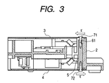
- Fig. 3 is a partially sectional view of the laser scanning apparatus cut along the line III-III of the top view of Fig. 2, i.e., a sectional view taken along the line passing just a center of the insertion pole 5c.
- shaded portions correspond to a section of the scanner case 2 and a portion indicated by halftone dot corresponds to a section of the metal pole 5 (5c).
- the upper cover 3 and the lower cover 4 are shown in a thin plate shape.
- both ends of the metal pole 5 are tapped.
- the upper cover 3 and the lower cover 4 can be secured to the metal pole 5 using metal screws 71 and 72.
- the metal pole 5 and the screws 71 and 72 constitute the conductive member.
- the metal pole 5 corresponds to a columnar support member.
- the metal pole 5 also partially functions as cover fixing means. This prevents an assembly procedure for the laser scanning apparatus from being much more complicated than before with the increased number of steps. Also, this embodiment adopts the cylindrical metal pole 5.
- the metal pole 5 is press-fitted into the scanner case 2 to ensure sufficient strength against rotation lest the metal pole 5 should rotate together with the screw upon fastening the covers with the screws.
- the metal pole may be formed to have a polygonal shape or a D-cut shape in section, for example, to thereby weaken the press-fitting strength and facilitate the separation.
- a conductive part 3g to be arranged to an image forming apparatus main body frame as the support part of the laser scanning apparatus is formed on the upper cover 3 in an integrated manner.
- the upper cover is solely grounded through the conductive part 3g.
- pitches between the metal poles are denoted by P (P1, P2, P3, P4, P5, and P6). It is generally known in the art that a distance between the ground positions is very important for reducing the unnecessary radiation noise as one of the problems to be solved by the present invention.
- the pitch P shown in Fig. 2 corresponds to the antenna length.
- the pitch P between the metal poles is desirably set to a distance (length) excluding lengths of ⁇ /2, ⁇ /4, and ⁇ /8, which easily allow the resonance to the noise frequency.
- the pitch is set to at least 1/2 of the minimum resonant antenna length (37.5 mm) within the noise control target range, that is, to not less than 1/16 of the wavelength ⁇ of the radiation at the frequency of 1 GHz. If being adjusted to 1/16 or more of the wavelength ⁇ , the pitch may theoretically equal none of the resonant antenna lengths with respect to the noise control target radiation.
- the metal pole by arranging the metal pole near a noise generating source such as a laser driver, a polygon motor driver, a BD drive substrate, and a wire harness extending from the substrate, a more significant effect can be expected.
- a noise generating source such as a laser driver, a polygon motor driver, a BD drive substrate, and a wire harness extending from the substrate
- the plural metal poles 5 for electrically connecting between the upper cover 3 and the lower cover 4 are screwed to both the covers.
- the metal poles 5 are press-fitted into the scanner case 2.
- a shearing stress ⁇ acts on the scanner case 2 in the directions of the arrows of Fig. 3.
- a fastening force between the cover(s) and the scanner case and strength of the scanner case itself oppose the stress.
- a fastening force between the upper cover 3 and the lower cover 4 and the metal poles 5 is added. Further, the press-fitted surfaces of the metal poles 5 absorb the stress.
- the strength against the shearing stress can be remarkably increased as compared with the conventional case.
- the shearing stress normally develops, for example, in the case where the image forming apparatus vibrates.
- the increase in strength against the stress i.e., vibration
- the upper metal cover 3 and the lower metal cover 4 are fastened to each other by using the metal poles 5, whereby grounding only one of the two covers makes it possible to set potentials of both the upper cover 3 and the lower cover 4 to a ground level. Consequently, the emission of the unnecessary radiation noise can be avoided.
- the metal pole 5 is inserted through the scanner case 2, making it unnecessary to perform a troublesome operation such as routing the ground wires for electrically connecting between the upper cover 3 and the lower cover 4 without impairing easiness of the assembly and the maintenance.
- the metal pole 5 partially functions as the cover fixing means, whereby no special assembly procedure is necessary for electrically connecting between the upper cover 3 and the lower cover 4.
- the metal poles 5 can be integrated into the scanner case 2, whereby the metal poles 5 function as reinforcing means for the scanner case 2 to enhance the strength of the scanner case 2.
- Fig. 4 is a perspective view showing a second embodiment of the present invention.
- the scanner case 2 has insertion openings 6e, 6f, 6g, and 6h, through which no metal pole is inserted in addition to the insertion openings 6a to 6d through which the metal poles 5a to 5d are actually inserted upon the assembly of the laser scanning apparatus in a one-to-one relationship. That is, the number of formed insertion openings is beyond that of metal poles to be actually inserted.
- the second embodiment is devised in view of the above problems.
- the insertion openings for the metal poles are formed in all positions as are effective positions for reducing the radiation noise in every image forming apparatus.
- the metal poles are selectively inserted while selecting the best arrangement of those insertion openings according to types (models) of the image forming apparatuses. More specifically, the metal poles are inserted through the insertion openings 6e to 6h of Fig. 4 in the case of mounting the laser scanning apparatus to another image forming apparatus having the different structure. With such a structure, even if the plural image forming apparatuses share one laser scanning apparatus, the arrangement of the ground positions which are most effective against the radiation noise of each image forming apparatus can be selected.
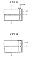
- Fig. 5 shows a third embodiment of the present invention.
- the metal poles 5 for electrically connecting the upper cover 3 and the lower cover 4 are press-fitted to the scanner case 2, enabling the reduction of the unnecessary noise and the increase in strength of the scanner case 2.
- one screw 25 may be merely inserted through the upper metal cover and the lower metal cover, after which adhesives etc. are used for preventing the rotation thereof.
- the screw may be a stepped screw 35.
- the screw can be fastened with a sufficient screw torque, which makes it possible to dispense with the aforementioned abrasives for preventing the rotation and to further facilitate the assembly.
- the positions where the electric wires are secured to the covers are desirably determined such that the distance therebetween does not equal the aforementioned resonant antenna length.
- the cover members can be simply and surely grounded.
- a laser scanning apparatus including: a laser light source; a rotary polygon mirror for deflecting a laser beam emitted from the laser light source for scanning; an imaging optical system for focusing the laser beam deflected by the rotary polygon mirror into an image; a containing member for containing the rotary polygon mirror and the imaging optical system; a first conductive cover member for closing a first opening portion of the containing member; a second conductive cover member for closing a second opening portion of the containing member; and conductive connection members for electrically connecting between the first conductive cover member and the second conductive cover member.
Landscapes
- Mechanical Optical Scanning Systems (AREA)
- Facsimile Scanning Arrangements (AREA)
- Electrophotography Configuration And Component (AREA)
Abstract
Description
- λ:
- wavelength [m]
- c:
- light velocity (3 × 10⁸ [m/s])
- f:
- frequency [Hz]
Claims (7)
- A laser scanning apparatus, comprising:a laser light source;a rotary polygon mirror for deflecting a laser beam emitted from the laser light source for scanning;an imaging optical system for focusing the laser beam deflected by the rotary polygon mirror into an image;a containing member for containing the rotary polygon mirror and the imaging optical system;a first conductive cover member for closing a first opening portion of the containing member;a second conductive cover member for closing a second opening portion of the containing member; anda conductive connection member for electrically connecting between the first conductive cover member and the second conductive cover member.
- A laser scanning apparatus according to claim 1, wherein the first conductive cover member covers an upper surface of the containing member and the second conductive cover member covers a lower surface of the containing member.
- A laser scanning apparatus according to claim 1, comprising a plurality of conductive connection members, wherein a distance between the conductive connection members is set not to equal lengths of λ/2, λ/4, and λ/8 where λ represents a wavelength of a target radiation noise.
- A laser scanning apparatus according to claim 1, wherein the conductive connection member has a mounting part for mounting the laser scanning apparatus to an apparatus in which the laser scanning apparatus is used.
- A laser scanning apparatus according to claim 1, wherein the conductive connection member has a metal pole.
- A laser scanning apparatus according to claim 5, wherein the metal pole is inserted through the containing member.
- A laser scanning apparatus according to claim 1, wherein the laser scanning apparatus is used for an image forming apparatus having a photosensitive member and adapted to scan the photosensitive member with a laser beam according to image information to form a latent image on the photosensitive member.
Applications Claiming Priority (2)
| Application Number | Priority Date | Filing Date | Title |
|---|---|---|---|
| JP2003075760 | 2003-03-19 | ||
| JP2003075760A JP4649095B2 (en) | 2003-03-19 | 2003-03-19 | Laser scanning device |
Publications (2)
| Publication Number | Publication Date |
|---|---|
| EP1464504A1 true EP1464504A1 (en) | 2004-10-06 |
| EP1464504B1 EP1464504B1 (en) | 2009-06-03 |
Family
ID=32844572
Family Applications (1)
| Application Number | Title | Priority Date | Filing Date |
|---|---|---|---|
| EP04006562A Expired - Lifetime EP1464504B1 (en) | 2003-03-19 | 2004-03-18 | Laser scanning apparatus |
Country Status (5)
| Country | Link |
|---|---|
| US (1) | US6829002B2 (en) |
| EP (1) | EP1464504B1 (en) |
| JP (1) | JP4649095B2 (en) |
| CN (2) | CN100394246C (en) |
| DE (1) | DE602004021305D1 (en) |
Families Citing this family (4)
| Publication number | Priority date | Publication date | Assignee | Title |
|---|---|---|---|---|
| JP2018060005A (en) | 2016-10-04 | 2018-04-12 | キヤノン株式会社 | Image formation apparatus |
| JP6867772B2 (en) | 2016-10-06 | 2021-05-12 | キヤノン株式会社 | Image forming device |
| CN108088364A (en) * | 2017-11-29 | 2018-05-29 | 深圳慎始科技有限公司 | A kind of rotation transmitting light formula laser scanning device |
| JP7516978B2 (en) * | 2020-08-24 | 2024-07-17 | 京セラドキュメントソリューションズ株式会社 | Optical scanning device, image forming device |
Citations (3)
| Publication number | Priority date | Publication date | Assignee | Title |
|---|---|---|---|---|
| JPH09236770A (en) * | 1996-02-28 | 1997-09-09 | Canon Inc | Scanning optical device |
| JPH11231250A (en) * | 1998-02-18 | 1999-08-27 | Canon Inc | Scanning optical device |
| JP2002328326A (en) * | 2001-04-27 | 2002-11-15 | Canon Inc | Scanning optical device |
Family Cites Families (11)
| Publication number | Priority date | Publication date | Assignee | Title |
|---|---|---|---|---|
| JPH04127116A (en) * | 1990-06-25 | 1992-04-28 | Ricoh Co Ltd | Image forming device |
| US5621451A (en) * | 1993-01-18 | 1997-04-15 | Canon Kabushiki Kaisha | Image forming apparatus |
| US5414492A (en) * | 1993-03-11 | 1995-05-09 | Canon Kabushiki Kaisha | Image forming apparatus with circuit board cover guiding recording medium |
| JP3382421B2 (en) * | 1995-06-30 | 2003-03-04 | キヤノン株式会社 | Information recording or reproducing device |
| JPH09304716A (en) * | 1996-05-14 | 1997-11-28 | Canon Inc | Optical deflection device |
| JPH10246862A (en) * | 1997-03-06 | 1998-09-14 | Canon Inc | Scanning optical device |
| JP2000249957A (en) * | 1999-03-04 | 2000-09-14 | Fuji Xerox Co Ltd | Optical scanner |
| JP2002107648A (en) * | 2000-10-03 | 2002-04-10 | Canon Inc | Image forming device |
| JP2002131674A (en) * | 2000-10-25 | 2002-05-09 | Asahi Optical Co Ltd | Scanning device |
| JP4024473B2 (en) * | 2000-11-29 | 2007-12-19 | 株式会社リコー | Optical scanning apparatus and image forming apparatus |
| EP1274039B1 (en) * | 2001-07-03 | 2008-01-02 | Symbol Technologies, Inc. | Compact scan module with magnetically centered scan mirror |
-
2003
- 2003-03-19 JP JP2003075760A patent/JP4649095B2/en not_active Expired - Fee Related
-
2004
- 2004-03-10 US US10/796,096 patent/US6829002B2/en not_active Expired - Lifetime
- 2004-03-16 CN CNB2006100826534A patent/CN100394246C/en not_active Expired - Fee Related
- 2004-03-16 CN CNA2004100086901A patent/CN1532580A/en active Pending
- 2004-03-18 DE DE602004021305T patent/DE602004021305D1/en not_active Expired - Lifetime
- 2004-03-18 EP EP04006562A patent/EP1464504B1/en not_active Expired - Lifetime
Patent Citations (3)
| Publication number | Priority date | Publication date | Assignee | Title |
|---|---|---|---|---|
| JPH09236770A (en) * | 1996-02-28 | 1997-09-09 | Canon Inc | Scanning optical device |
| JPH11231250A (en) * | 1998-02-18 | 1999-08-27 | Canon Inc | Scanning optical device |
| JP2002328326A (en) * | 2001-04-27 | 2002-11-15 | Canon Inc | Scanning optical device |
Non-Patent Citations (3)
| Title |
|---|
| PATENT ABSTRACTS OF JAPAN vol. 1998, no. 01 30 January 1998 (1998-01-30) * |
| PATENT ABSTRACTS OF JAPAN vol. 1999, no. 13 30 November 1999 (1999-11-30) * |
| PATENT ABSTRACTS OF JAPAN vol. 2003, no. 03 5 May 2003 (2003-05-05) * |
Also Published As
| Publication number | Publication date |
|---|---|
| JP2004286819A (en) | 2004-10-14 |
| US20040183894A1 (en) | 2004-09-23 |
| CN1532580A (en) | 2004-09-29 |
| CN1847920A (en) | 2006-10-18 |
| DE602004021305D1 (en) | 2009-07-16 |
| CN100394246C (en) | 2008-06-11 |
| EP1464504B1 (en) | 2009-06-03 |
| JP4649095B2 (en) | 2011-03-09 |
| US6829002B2 (en) | 2004-12-07 |
Similar Documents
| Publication | Publication Date | Title |
|---|---|---|
| US9581929B2 (en) | Optical scanning apparatus, image forming apparatus, and support member for an optical scanning apparatus | |
| JP2006234977A (en) | Optical scanning apparatus and image forming apparatus | |
| US6829002B2 (en) | Laser scanning apparatus | |
| JP4223175B2 (en) | Optical scanning device | |
| JP2000258712A (en) | Optical scanner | |
| JPH0973039A (en) | Optical deflection device | |
| JP2000249957A (en) | Optical scanner | |
| JP2007121586A (en) | Optical scanner | |
| JPH11245442A (en) | Scanning optical device | |
| JP2003015071A (en) | Optical writing device | |
| JPH09120039A (en) | Deflection scanning device | |
| JP3530690B2 (en) | Deflection scanning device | |
| JP2002328326A (en) | Scanning optical device | |
| JPH11194293A (en) | Deflection scanning device | |
| CN111198485A (en) | Optical writing device and image forming apparatus | |
| JPH10115794A (en) | Deflection scanning device | |
| JP2005202117A (en) | Scanning optical device | |
| JPH11202252A (en) | Scanning optical device | |
| JPH1152270A (en) | Deflection scanning device | |
| JP2002350768A (en) | Laser scanner and image forming device using the same | |
| JP2004205786A (en) | Scanning optical device | |
| JP2006091453A (en) | Scanning optical device | |
| JP2003248185A (en) | Scanning optical device and image forming apparatus | |
| JP2001166241A (en) | Deflection scanning device | |
| JPH1152269A (en) | Deflection scanning device |
Legal Events
| Date | Code | Title | Description |
|---|---|---|---|
| PUAI | Public reference made under article 153(3) epc to a published international application that has entered the european phase |
Free format text: ORIGINAL CODE: 0009012 |
|
| AK | Designated contracting states |
Kind code of ref document: A1 Designated state(s): AT BE BG CH CY CZ DE DK EE ES FI FR GB GR HU IE IT LI LU MC NL PL PT RO SE SI SK TR |
|
| AX | Request for extension of the european patent |
Extension state: AL LT LV MK |
|
| 17P | Request for examination filed |
Effective date: 20050217 |
|
| AKX | Designation fees paid |
Designated state(s): DE FR GB IT |
|
| 17Q | First examination report despatched |
Effective date: 20051026 |
|
| GRAP | Despatch of communication of intention to grant a patent |
Free format text: ORIGINAL CODE: EPIDOSNIGR1 |
|
| GRAS | Grant fee paid |
Free format text: ORIGINAL CODE: EPIDOSNIGR3 |
|
| GRAA | (expected) grant |
Free format text: ORIGINAL CODE: 0009210 |
|
| AK | Designated contracting states |
Kind code of ref document: B1 Designated state(s): DE FR GB IT |
|
| REG | Reference to a national code |
Ref country code: GB Ref legal event code: FG4D |
|
| REF | Corresponds to: |
Ref document number: 602004021305 Country of ref document: DE Date of ref document: 20090716 Kind code of ref document: P |
|
| PLBE | No opposition filed within time limit |
Free format text: ORIGINAL CODE: 0009261 |
|
| STAA | Information on the status of an ep patent application or granted ep patent |
Free format text: STATUS: NO OPPOSITION FILED WITHIN TIME LIMIT |
|
| 26N | No opposition filed |
Effective date: 20100304 |
|
| REG | Reference to a national code |
Ref country code: FR Ref legal event code: PLFP Year of fee payment: 13 |
|
| PGFP | Annual fee paid to national office [announced via postgrant information from national office to epo] |
Ref country code: IT Payment date: 20160307 Year of fee payment: 13 |
|
| PGFP | Annual fee paid to national office [announced via postgrant information from national office to epo] |
Ref country code: FR Payment date: 20160324 Year of fee payment: 13 |
|
| REG | Reference to a national code |
Ref country code: FR Ref legal event code: ST Effective date: 20171130 |
|
| PG25 | Lapsed in a contracting state [announced via postgrant information from national office to epo] |
Ref country code: FR Free format text: LAPSE BECAUSE OF NON-PAYMENT OF DUE FEES Effective date: 20170331 |
|
| PG25 | Lapsed in a contracting state [announced via postgrant information from national office to epo] |
Ref country code: IT Free format text: LAPSE BECAUSE OF NON-PAYMENT OF DUE FEES Effective date: 20170318 |
|
| PGFP | Annual fee paid to national office [announced via postgrant information from national office to epo] |
Ref country code: GB Payment date: 20190327 Year of fee payment: 16 |
|
| PGFP | Annual fee paid to national office [announced via postgrant information from national office to epo] |
Ref country code: DE Payment date: 20190531 Year of fee payment: 16 |
|
| REG | Reference to a national code |
Ref country code: DE Ref legal event code: R119 Ref document number: 602004021305 Country of ref document: DE |
|
| PG25 | Lapsed in a contracting state [announced via postgrant information from national office to epo] |
Ref country code: DE Free format text: LAPSE BECAUSE OF NON-PAYMENT OF DUE FEES Effective date: 20201001 |
|
| GBPC | Gb: european patent ceased through non-payment of renewal fee |
Effective date: 20200318 |
|
| PG25 | Lapsed in a contracting state [announced via postgrant information from national office to epo] |
Ref country code: GB Free format text: LAPSE BECAUSE OF NON-PAYMENT OF DUE FEES Effective date: 20200318 |