EP1464499A2 - Ink jet head cleaning apparatus and ink jet recording apparatus - Google Patents
Ink jet head cleaning apparatus and ink jet recording apparatus Download PDFInfo
- Publication number
- EP1464499A2 EP1464499A2 EP04251172A EP04251172A EP1464499A2 EP 1464499 A2 EP1464499 A2 EP 1464499A2 EP 04251172 A EP04251172 A EP 04251172A EP 04251172 A EP04251172 A EP 04251172A EP 1464499 A2 EP1464499 A2 EP 1464499A2
- Authority
- EP
- European Patent Office
- Prior art keywords
- ink jet
- nozzle face
- ink
- jet head
- contact member
- Prior art date
- Legal status (The legal status is an assumption and is not a legal conclusion. Google has not performed a legal analysis and makes no representation as to the accuracy of the status listed.)
- Withdrawn
Links
Images


Classifications
-
- B—PERFORMING OPERATIONS; TRANSPORTING
- B41—PRINTING; LINING MACHINES; TYPEWRITERS; STAMPS
- B41J—TYPEWRITERS; SELECTIVE PRINTING MECHANISMS, i.e. MECHANISMS PRINTING OTHERWISE THAN FROM A FORME; CORRECTION OF TYPOGRAPHICAL ERRORS
- B41J2/00—Typewriters or selective printing mechanisms characterised by the printing or marking process for which they are designed
- B41J2/005—Typewriters or selective printing mechanisms characterised by the printing or marking process for which they are designed characterised by bringing liquid or particles selectively into contact with a printing material
- B41J2/01—Ink jet
- B41J2/135—Nozzles
- B41J2/165—Prevention or detection of nozzle clogging, e.g. cleaning, capping or moistening for nozzles
- B41J2/16585—Prevention or detection of nozzle clogging, e.g. cleaning, capping or moistening for nozzles for paper-width or non-reciprocating print heads
Definitions
- the present invention relates to an ink jet head cleaning apparatus for cleaning an ink jet head which has a nozzle face provided with nozzle outlets for discharging droplets of ink from the outlets and an ink head recording apparatus having the ink jet head.
- the ink jet recording apparatus is provided with an ink jet head having a nozzle face in which outlets are formed to discharge droplets of ink from nozzles to a recording medium.
- the apparatus therefore, functions to record images on the recording medium by means of the ink jet head.
- the nozzle face of the ink jet head is sometimes smeared with sprayed ink resulting from the impingement of ink droplets on the recording medium.
- a little energy is used to discharge ink droplets from the nozzles.
- the ink jet head is mounted about several millimeters off from the recording medium, the nozzle face is likely to be smeared with the sprayed ink, resulting inoccurrence of cloggednozzles. If the clogging of nozzles once occurs, it is difficult to eliminate nozzle clogging because a little pressure is used for ink discharge from the nozzles.
- extraneous matters holding on the nozzle face may be ink, ink pigments remaining after the evaporation of ink solvents, fibers of the recording medium, and, furthermore, a mixture of all of these extraneous matters.
- These extraneous matters are sometimes hard to remove by the use of a flexible wipe blade. In such a case, it is a general practice to perform a regular maintenance, besides the wiping operation, to thereby remove the extraneous matters.
- the foreign substance in case there remains an extraneous matter (hereinafter called the "foreign substance") which can not be removed by the wipe blade during a period until a subsequent maintenance, the foreign substance will gradually grow larger by uniting with ink and fibers remaining around, finally resulting in deteriorated ink discharge stability and straight discharge of ink. Therefore, it is important to prevent the growth of the foreign substances holding on the nozzle face during a period until the subsequent maintenance.
- Fig. 9A is an enlarged longitudinal sectional side view schematically showing a nozzle face 102 of an ink jet head 101 before wiping by a conventional wipe blade 100.
- Fig. 9B is an enlarged longitudinal sectional side view schematically showing the nozzle face 102 of the ink jet head 101 during wiping by the conventional wipe blade 100.
- Fig. 9C is an enlarged longitudinal sectional side view schematically showing the nozzle face 102 of the ink jet head 101 after wiping by the conventional wipe blade 100.
- a foreign substance F1 that can not be removed by the wipe blade 100 adheres heaping up on the nozzle face 102 of the ink jet head 101.
- a foreign substance F2 that can be removed by the wipe blade 100 also attaches on the nozzle face 102.
- the top end of the wipe blade 100 strikes on the foreign substance F1, causing a clearance to occur between the wipe blade 100 and the nozzle face 102. Therefore, the foreign substance F2 that has flowed into the clearance or the foreign substance F2 that is present in the clearance is not removed, remaining on the nozzle face 102 as shown in Fig. 9C.
- the flexible wipe blade 100 It is impossible for the flexible wipe blade 100 to fully uniformly be in contact with the nozzle face 102. There is, therefore, apprehension that non-uniform wiping will occur.
- the nozzle face 102 is made ink repellent so that the ink will be repelled. If the ink-repellent nozzle face 102 is wiped, easy-to-suck large droplets of ink are especially spread thin on the nozzle face 102 in a fine form of droplets of ink which is hard to suck. The fine ink droplets are prone to dry soon; therefore, if left as spread, the droplets will be stuck on the nozzle face 102, resulting in impaired ink repellency of the nozzle face 102.
- the wipe blade 100 being formed of a flexible material, is likely to force the foreign substance F2 on the nozzle face 102 back into the nozzle during wiping operation.
- the nozzle will be clogged or deformed. Therefore, nozzle clogging will become a factor to deteriorate the ink discharge stability, and also nozzle deformation will be a cause to deteriorate straight discharge of ink.
- an object of the present invention to provide an ink jet head cleaning apparatus and an ink jet recording apparatus which can prevent the deterioration of ink discharge stability and straight discharge of ink.
- the object of the present invention is accomplished by a new ink jet head cleaning apparatus and ink jet recording apparatus of the invention.
- the new ink jet head cleaning apparatus of the present invention is comprised of a flexible contact member which is mounted in a position where the top end thereof comes into contact with a nozzle face of an ink jet head having the nozzle face provided with outlets for discharging ink in a form of droplets, and is movable along the nozzle face; and a driving unit which correlatively moves the ink jet head and the contact member.
- the top end of the contact member is divided into a plurality of sections in a direction orthogonal to the direction of its movement.
- the new ink jet recording apparatus of the present invention is comprised of an ink jet head having a nozzle face provided with outlets for discharging ink in a form of droplets; a flexible contact member which is mounted in a position where the top end thereof comes into contact with the nozzle face, and is movable along the nozzle face; and a driving unit for correlatively moving the ink jet head and the contact member.
- the leading end of the contact member is divided into a plurality of sections in a direction orthogonal to the direction of its movement.
- the new ink jet head cleaning apparatus of the present invention is comprised of a contact member which is mounted in a position where it comes into contact with a nozzle face of an ink jet head which has the nozzle face provided with outlets to discharge ink in a form of droplets and is movable along the nozzle face; a suction section for sucking ink droplets holding on the nozzle face; and a driving unit which correlatively moves the ink jet head and the contact member.
- the contact member is provided on the contact surface which is in contact with the nozzle face andhas grooveportions extending in the direction of movement.
- the new ink jet recording apparatus of the present invention is comprised of an ink jet head having a nozzle face provided with outlets from which ink is discharged in a form of droplets; a contact member mounted in a position where it comes into contact with the nozzle face and moves along the nozzle face; a suction section which sucks ink droplets attached on the nozzle face; and a first driving unit for correlatively moving the ink jet head and the contact member.
- the contact member is provided with groove portions on the contact surface which comes into contact with the nozzle face, extending in the direction of its movement.
- the first embodiment of the present invention will now be described with reference to Fig. 1 to Fig. 4.
- the present embodiment gives an example of application of the ink jet head cleaning apparatus to the ink jet recording apparatus 1.
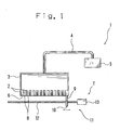
- Fig. 1 is a front view schematically showing the ink jet recording apparatus 1 of the present embodiment.
- the ink jet recording apparatus 1 is provided with an ink jet head 3 which discharges ink in a form of droplets from a nozzle 2, an ink tank 5 for holding ink which is connected to the ink jet head 3 through an ink supply line 4, and a cleaning section 7 for cleaning a nozzle face 6 of the ink jet head 3.
- the ink jet recording apparatus 1 is also provided with a conveyor (not shown) which successively feeds out and carries the sheet, which is a recording medium, in the sub-scanning direction, and a carriage (not shown) for carrying in the main scanning direction the ink jet head 3 mounted thereon.
- the ink jet head 3 is provided with a plurality of nozzles 2 arranged nearly in a straight line.
- the plurality of nozzles 2 are arranged in a straight line and also arranged in some cases slightly deviated from the straight line.
- outlets 8 of the nozzles 2 are formed nearly in the straight line. That is, the ink jet head 3 is so constituted as to discharge ink in a form of droplets from the outlets 8 of the nozzle face 6.
- the ink jet head 3 used is a piezoelectric type ink jet head 3 fitted with a piezoelectric-crystal element or a thermal ink jet type ink jet head 3 using a heating element.
- the cleaning section 7 is comprised of a wipe blade 10 which is mounted in a position where its top end 9 comes into contact with the nozzle face 6 of the ink jet head 3, and is movable along the nozzle face 6 (e.g., in the direction of arrangement of the nozzles 2 (outlets 8)), and a driving unit 11 for moving the wipe blade 10 in the direction of arrangement of the nozzles 2.
- the wipe blade 10 stated above functions as a contact member.
- the driving unit 11 is comprised of a guide screw 12 for moving to guide the wipe blade 10 in the direction of arrangement of the plurality of nozzles 2, and a driving motor 13 for driving the guide screw 12.
- the wipe blade 10, holding its top end 9 in contact with the nozzle face 6, is driven by the driving unit 11 in the direction of arrangement of the plurality of nozzles 2, thus wiping the nozzle face 6 of the ink jet head 3.
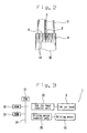
- Fig. 2 is an enlarged longitudinal sectional side view schematically showing the wipe blade 10 of the ink jet recording apparatus 1 of the present embodiment.
- the wipe blade 10 is formed flat of a flexible material, e.g., rubber.
- the top end (The end) 9 of the wipe blade 10 is divided into a plurality of sections along the nozzle face 6, that is, nearly in a direction orthogonal to the direction of movement of the wipe blade 10. Therefore, the wipe blade 10 has a plurality of slits 14 in the contact surface which comes into contact with the nozzle face 6, extending in the direction of movement of the wipe blade 10.
- Fig. 3 is a block diagram schematically showing electric connection of each part of the ink jet recording apparatus 1 according to the present embodiment.
- the ink jet recording apparatus 1 has a built-in controller 20.
- the controller 20 includes a CPU (central processing unit) 21 which centrally controls each part, a ROM (read only memory) 22 which stores various kinds of control programs to be run by the CPU 21, and a RAM (random access memory) 23 which functions as a work area of the CPU 21.
- the CPU, the ROM and the RAM are connected by a bus line 24.
- the ink jet head 3 is connected through an ink jet head control unit 25.
- the driving motor 13 is connected through a driving motor control unit 26.
- a conveyor (not shown) andacarriage (not shown) are connected through the drive control unit (not shown).
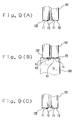
- Fig. 4A is an enlarged longitudinal sectional side view schematically showing the nozzle face 6 of the ink jet head 3 before wiping by the wipe blade 10 of the present embodiment.
- Fig. 4B is an enlarged longitudinal sectional side view schematically showing the nozzle face 6 of the ink jet head 3 during wiping by the wipe blade 10 of the present embodiment.
- Fig. 4C is an enlarged longitudinal sectional side view schematically showing the nozzle face 6 of the ink jet head 3 after wiping by the wipe blade 10 of the present embodiment.
- the foreign substance F1 e.g., a dry solidified mixture of ink drops and fibers
- the foreign substance 2 e.g., wet ink drops
- the ink jet recording apparatus 1 drives to control the cleaning section 7 during non-recording operation of the ink jet head 3. That is, the ink jet recording apparatus 1 drives to control the driving motor 13 to turn the guide screw 12, moving the wipe blade 10 while holding the top end 9 in contact with the nozzle face 6.
- the cleaning operation i.e., the wiping operation
- the top end 9 of the wipe blade 10 is divided into a plurality of sections. Therefore, a part of the top end 9 rides on the foreign substance F1, while the other part of the top end 9 is in a desirable state of contact with the nozzle face 6. Consequently, there will not occur such a large clearance that allows the foreign substance F2 to flow in between the wipe blade 10 and the nozzle face 6.
- the foreign substance F2 is removed completely from the nozzle face 6 by the wipe blade 10.
- the foreign substance F1 that can not be removed by the wipe blade 10 remains on the nozzle face 6 but can be removed by regular maintenance jobs.
- the foreign substance F1 is present on the nozzle face 6 until the maintenance job is performed.
- the foreign substance F2 will not grow large because it is removed completely from the nozzle face 6 by the wipe blade 10 by every wiping operation. Therefore, the foreign substance F1 will not become a factor to deteriorate ink discharge stability and straight discharge of ink.
- the nozzle face 6 is wiped with the wipe blade 10 having the top end 9 divided into a plurality of sections.
- the wipe blade 10 having the top end 9 divided into a plurality of sections.
- the second embodiment of the present invention will be explained with reference to Fig. 5 to Fig. 8. It should be noted that the same members as those in the first embodiment are designated by the same reference numerals.
- the present embodiment is an example of application of the ink jet head cleaning apparatus to the ink jet recording apparatus 1A.
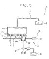
- Fig. 5 is a front view schematically showing the ink jet recording apparatus 1A of the present embodiment.
- the ink jet recording apparatus 1A is provided with the ink jet head 3 which discharges ink from the nozzles 2 in a form of droplets to the recording medium, the ink tank 5 for holding ink which is connected to the ink jet head 3 through the ink supply line 4, and the cleaning section 7A for cleaning the nozzle 2 and nozzle face 6 of the ink jet head 3.
- the ink jet head 3 has a plurality of nozzles 2 formed nearly in a straight line.
- the plurality of nozzles 2 are arranged in a straight line and in some cases slightly deviated from the straight line.
- the outlets 8 of the nozzles 2 are formed nearly in the straight line. That is, the ink jet head 3 is so constituted that ink can be discharged in a form of droplets from the outlets 8 of the nozzle face 6.
- the ink jet head 3 there is used the piezoelectric type ink jet head 3 provided with a piezoelectric-crystal element or the thermal ink jet type ink jet head 3 with a heating element.
- the cleaning section 7A is comprised of the wipe blade 10A which is mounted in a position where its top end 9 comes into contact with the nozzle face 6 of the ink jet head 3, and is movable along the nozzle face 6 (e.g., in the direction of arrangement of the nozzles 2 (outlets 8)) and which sucks ink from the nozzles 2 and the nozzle face 6, a suction section 31 which has a suction head 30 positioned oppositely to the nozzle face 6, movably along the nozzle face 6 (e.g., in the direction of arrangement of the nozzles 2 (outlets 8)), and the driving unit 11 for moving the wipe blade 10A and the suction head 30 in the direction of arrangement of the plurality of nozzles2.
- the wipe blade 10A stated above functions as a contact member.
- the suction section 31 is positioned upstream of the wipe blade 10A in the direction of suction and movement, but is not limited thereto.
- the driving unit 11 is comprised of the guide screw 12 which moves to guide the wipe blade 10A in the direction of arrangement of the plurality of nozzles 2, and the driving motor 13 for driving to turn the guide screw 12.
- the driving unit 11 functions as the first and second driving units.
- the wipe blade 10A and the suction head 30 are moved simultaneously by means of the driving unit 11 alone.
- the drivingmeans is not limited to the driving unit 11.
- a couple of driving units 11 may be employed to separately move the wipe blade 10A and the suction head 30.
- the wipe blade 10A is moved by the driving unit 11 in the direction of arrangement of the plurality of nozzles 2, with the top end 9 kept in contact with the nozzle face 6, thereby wiping the nozzle face 6 of the ink jet head 3.
- the suction section 31 is constituted by connecting to the suction head 30 which covers a part of the plurality of outlets 8 in the ink jet head 3, a suction pump 32 which produces a suction force for sucking ink from the nozzle 2 and the nozzle face 6, and a waste ink tank 33 for holding sucked waste ink through an ink discharge line 34.
- the suction head 30 is moved by the driving unit 11 in the direction of arrangement of the nozzles 2, the suction section 31 sucks ink from all the nozzles 2 and the nozzle face 6 of the ink jet head 3 after wiping operation is completed by the wipe blade 10A.
- the suction head 30 is so constituted as to cover a part of the plurality of nozzles 2, but is not limited to the constitution.
- the suction head 30 may be so constituted as to cover all of the nozzles 2 to thereby hold the nozzles from moving.
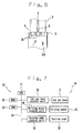
- Fig. 6 is an enlarged longitudinal sectional side view schematically showing the wipe blade 10A of the ink jet recording apparatus 1A according to the present embodiment.
- the wipe blade 10A is formed flat of a flexible material, e.g., rubber.
- a plurality of groove portions 35 are formed extending in the direction of travel of the wipe blade 10A. Therefore, the wipe blade 10A is provided with the plurality of groove portions 35 in the contact surface which comes into contact with the nozzle face 6, extending in the direction of its movement.
- One of the plurality of groove portions 35 is located in a position opposite to the nozzle 2.
- the plurality of groove portions 35 are formed at a regular spacing but are not limited thereto, and may be formed at a different spacing for example. Furthermore, the plurality of groove portions 35 are formed to the same width, but are not limited to the width. The groove portions 35 may be formed to different widths for example. Furthermore, the plurality of groove portions 35 are all formed square in cross section, but are not limited thereto; that is, the groove portions 35 may be formed triangular in cross section and each of the groove portions 35 may be formed in different cross section. Furthermore, the groove portions 35 are formed plural but are not limited thereto. The number of the groove portion 35 may be one for example.
- Fig. 7 is a block diagram schematically showing the electric connection of each part of the ink jet recording apparatus 1A according to the present embodiment.
- the ink jet recording apparatus 1A has a built-in controller 20.
- the controller 20 comprises a CPU (central processing unit) 21 which centrally controls each part, a ROM (read only memory) 22 which stores various kinds of control programs to be run by the CPU 21, and a RAM (random access memory) 23 which functions as a work area of the CPU 21; the CPU, the ROM and the RAM being connected by a bus line 24.
- the ink jet head 3 is connected through an ink jet head control unit 25.
- the driving motor 13 is connected through the driving motor control unit 26 and the suction pump 32 is connected through the suction pump control unit 36.
- Fig. 8A is a perspective outside view schematically showing the nozzle face 6 of the ink jet head 3 before wiping by the use of the wipe blade 10A according to the present embodiment.
- Fig. 8B is an enlarged perspective outside view schematically showing the nozzle face 6 of the ink jet head 3 after wiping by the wipe blade 10A according to the present embodiment.
- the ink jet recording apparatus 1A drives to control the cleaning section 7A during the non-recording operation of the ink jet head 3. That is, the ink jet recording apparatus 1A drives the driving motor 13 to turn the guide screw 12, thereby moving the wipe blade 10A and the suction head 30 of the suction section 31.
- the top end 9 of the wipe blade 10A travels while in contact with the nozzle face 6; and the suction section 31 also travels while sucking ink from the nozzle 2 and the nozzle face 6, therebyperforming the cleaning operation (e.g., wiping operation and suction operation).
- the nozzle face 6 is wiped by the wipe blade 10A having the groove portions 35 in the top end 9, thereby collecting the fine ink droplets scattered on the nozzle face 6.
- the ink droplets thus collected become an easy-to-suck large drops of ink (ink accumulation), thereby enabling the suction section 31 to reliably suck the large ink drops from the nozzle face 6. Therefore the fine ink droplets are removed completely from the nozzle face 6, preventing deterioration of ink discharge stability and straight discharge of ink. Consequently, the occurrence of defective printing can be prevented.
- one of the plurality of groove portions 35 is positioned oppositely to the nozzle 2, so that the top end 9 of the wipe blade 10A will not move on the nozzles 2 in contact with the outlets 8 of the nozzles 2. Therefore, it is possible to prevent entrance of foreign substances (adherent ink and fibers) into the nozzles 2 and consequently to prevent clogging of the nozzles 2.
- the wipe blade 10A has the plurality of groove portions 35 in the contact surface thereof which comes into contact with the nozzle face 6. That is, a required number of groove portions 35 are cut in accordance with the size of the contact surface, so that fine ink droplets scattered on the nozzle surface 6 can be efficiently collected. Furthermore, the wipe blade 10A and the suction head 30 are moved by one driving unit 11, and therefore it is possible to realize space saving and cost reduction as compared with the case of provision of two driving units 11.
- the cleaning section 7, 7A is moved by the driving unit 11 in relation to the ink jet head 3, but it should be noticed that the driving means is not limited to the driving unit 11; the cleaning section 7, 7A and the ink jet head 3 are required to correlatively move.
- the ink jet head 3 may be so constituted as to move in relation to the cleaning section 7, 7A.
Landscapes
- Ink Jet (AREA)
Abstract
Description
Claims (14)
- An ink jet head cleaning apparatus (7), comprising:characterized in that the end of the contact member is divided into a plurality of sections in a direction orthogonal to the direction of its movement.a flexible contact member (10) which is mounted in a position where an end (9) of the contact member comes into contact with a nozzle face (6) of an ink jet head (3) provided with outlets (8) for discharging ink in a form of droplets, and is movable along the nozzle face; anda driving unit (11) which correlatively moves the ink jet head and the contact member,
- An ink jet recording apparatus (1), comprising:characterized in that the end of the contact member is divided into a plurality of sections in a direction orthogonal to the direction of its movement.an ink jet head (3) having a nozzle face (6) provided with outlets (8), and discharging ink from the outlets in a form of droplets;a flexible contact member (10) which is mounted in a position where an end (9) of the contact member comes into contact with the nozzle face and is movable along the nozzle face; anda driving unit (11) for correlatively moving the ink jet head and the contact member,
- An ink jet head cleaning apparatus (7A), comprising:characterized in that the contact member has groove portions (35) in the contact surface which comes into contact with the nozzle face, extending in the direction of its movement.a contact member (10A) which is positioned in contact with a nozzle face (6) of an ink jet head (3) provided with outlets (8) for discharging ink in a form of droplets, and is movable along the nozzle face;a suction section (31) for sucking ink droplets holding on the nozzle face; anda first driving unit (11) which correlatively moves the ink jet head and the contact member,
- An ink jet head cleaning apparatus according to claim 3, wherein the plurality of outlets are formed in a straight line; and
the groove portions are provided in a position opposite to the outlets. - An ink jet cleaning apparatus according to claim 3, wherein the plurality of groove portions are provided.
- An ink jet cleaning apparatus according to claim 4, wherein the plurality of groove portions are provided.
- An ink jet head cleaning apparatus according to claim 3, wherein the plurality of outlets are provided; and
the suction section has a suction head (30) covering a part of the plurality of outlets,
furthermore is comprised of a second driving unit (11) which correlatively moves the ink jet head and the suction head. - An ink jet head cleaning apparatus according to claim 7, wherein the first driving unit and the second driving unit are commonly usable.
- An ink jet recording apparatus (1A), comprising:characterized in that the contact member has groove portions (35) in the contact surface being in contact with the nozzle face, extending in the direction of its movement.an ink jet head (3) having a nozzle face (6) provided with outlets (8), and discharging ink from the outlets in a form of droplets;a contact member (10A) which is positioned in contact with the nozzle face and movable along the nozzle face;a suction section (31) for sucking ink droplets holding on the nozzle face; anda first driving unit (11) for correlatively moving the ink jet head and the contact member,
- An ink j et recording apparatus according to claim 9, wherein the plurality of outlets are formed in a straight line; and the groove portions are positioned oppositely to the outlets.
- An ink j et recording apparatus according to claim 9, wherein the plurality of groove portions are provided.
- An ink jet recording apparatus according to claim 10, wherein the plurality of groove portions are provided.
- An ink j et recording apparatus according to claim 9, wherein the plurality of outlets are provided; and
the suction section has a suction head (30) covering a part of the plurality of outlets,
furthermore is comprised of a second driving unit (11) for correlatively moving the ink jet head and the suction head. - An ink jet recording apparatus according to claim 13, wherein the first driving unit and the second driving unit are commonly usable.
Applications Claiming Priority (2)
| Application Number | Priority Date | Filing Date | Title |
|---|---|---|---|
| US395960 | 1995-02-28 | ||
| US10/395,960 US20040189735A1 (en) | 2003-03-24 | 2003-03-24 | Ink jet head cleaning apparatus and ink jet recording apparatus |
Publications (2)
| Publication Number | Publication Date |
|---|---|
| EP1464499A2 true EP1464499A2 (en) | 2004-10-06 |
| EP1464499A3 EP1464499A3 (en) | 2005-08-10 |
Family
ID=32850531
Family Applications (1)
| Application Number | Title | Priority Date | Filing Date |
|---|---|---|---|
| EP04251172A Withdrawn EP1464499A3 (en) | 2003-03-24 | 2004-03-01 | Ink jet head cleaning apparatus and ink jet recording apparatus |
Country Status (3)
| Country | Link |
|---|---|
| US (1) | US20040189735A1 (en) |
| EP (1) | EP1464499A3 (en) |
| JP (1) | JP2004284352A (en) |
Families Citing this family (11)
| Publication number | Priority date | Publication date | Assignee | Title |
|---|---|---|---|---|
| US20040257396A1 (en) * | 2003-06-19 | 2004-12-23 | Toshiba Tec Kabushiki Kaisha | Ink jet head cleaning apparatus and ink jet recording apparatus |
| US7467845B2 (en) * | 2003-09-22 | 2008-12-23 | Fujifilm Corporation | Image forming apparatus |
| US7044580B2 (en) * | 2003-11-18 | 2006-05-16 | Toshiba Tec Kabushiki Kaisha | Ink jet recording head maintenance apparatus and ink jet recording apparatus |
| JP4882627B2 (en) * | 2005-09-21 | 2012-02-22 | ブラザー工業株式会社 | Droplet ejector |
| US7648219B2 (en) * | 2005-09-21 | 2010-01-19 | Brother Kogyo Kabushiki Kaisha | Liquid-droplet jetting apparatus having a movable body for detecting and purging abnormal nozzles |
| KR101692270B1 (en) * | 2010-11-12 | 2017-01-05 | 삼성전자 주식회사 | Cleaning apparatus of ink-jet head and method thereof |
| TWM477382U (en) * | 2013-12-11 | 2014-05-01 | 三緯國際立體列印科技股份有限公司 | Cleaning device |
| JP6497024B2 (en) * | 2014-05-21 | 2019-04-10 | 株式会社リコー | Droplet discharge head recovery mechanism |
| JP6429635B2 (en) * | 2015-01-16 | 2018-11-28 | キヤノン株式会社 | Inkjet recording device |
| JP2019043040A (en) * | 2017-09-01 | 2019-03-22 | 東芝テック株式会社 | Cleaning device and inkjet recording device |
| JP2023072468A (en) * | 2021-11-12 | 2023-05-24 | ブラザー工業株式会社 | Liquid discharge apparatus and wiper used in liquid discharge apparatus |
Family Cites Families (23)
| Publication number | Priority date | Publication date | Assignee | Title |
|---|---|---|---|---|
| JPS5675867A (en) * | 1979-11-22 | 1981-06-23 | Seiko Epson Corp | Ink jet recorder |
| JP2946725B2 (en) * | 1989-11-06 | 1999-09-06 | セイコーエプソン株式会社 | Ink jet recording device |
| JPH03290261A (en) * | 1990-01-30 | 1991-12-19 | Canon Inc | Wiping device for inkjet recording device |
| DE69120569T2 (en) * | 1990-02-26 | 1997-01-09 | Canon Kk | Ink jet recording apparatus and method for cleaning the recording head |
| JP2978328B2 (en) * | 1992-05-11 | 1999-11-15 | キヤノン株式会社 | Ink jet recording apparatus and ink jet head recovery method |
| DE69418351T2 (en) * | 1993-02-02 | 1999-12-30 | Seiko Epson Corp., Tokio/Tokyo | Process for filling ink passages with ink |
| JPH06320744A (en) * | 1993-04-19 | 1994-11-22 | Xerox Corp | Wet wipe maintenance device for full width inkjet printer |
| US5612722A (en) * | 1993-10-26 | 1997-03-18 | Lexmark International, Inc. | Ink jet printhead wiper having side surfaces intersecting a top surface at acute angles to form wiping edges and a slat centered in a bottom surface |
| US5805180A (en) * | 1994-08-26 | 1998-09-08 | Canon Kabushiki Kaisha | Ink jet recording apparatus which performs suction recovery with a cap and method for same |
| JPH106516A (en) * | 1996-06-25 | 1998-01-13 | Oki Data:Kk | Inkjet printer |
| JPH1044445A (en) * | 1996-08-07 | 1998-02-17 | Minolta Co Ltd | Inkjet head maintenance device |
| JP3329367B2 (en) * | 1996-10-21 | 2002-09-30 | セイコーエプソン株式会社 | Ink jet recording device |
| JPH10151759A (en) * | 1996-11-22 | 1998-06-09 | Canon Inc | Ink jet printing apparatus and method for removing insoluble matter |
| JP3169853B2 (en) * | 1997-03-04 | 2001-05-28 | 新潟日本電気株式会社 | Wiper structure |
| US6120126A (en) * | 1997-03-18 | 2000-09-19 | Brother Kogyo Kabushiki Kaisha | Ink jet printer |
| JP4138981B2 (en) * | 1998-01-16 | 2008-08-27 | オセ−テクノロジーズ・ベー・ヴエー | Method and apparatus for cleaning an inkjet printhead |
| JP2000103072A (en) * | 1998-09-29 | 2000-04-11 | Canon Inc | Recovery device for inkjet recording device |
| JP3903652B2 (en) * | 1999-07-09 | 2007-04-11 | セイコーエプソン株式会社 | Inkjet recording device |
| JP2002166576A (en) * | 2000-11-30 | 2002-06-11 | Canon Inc | Liquid ejection device and ejection recovery method of the device |
| JP2002254663A (en) * | 2001-02-27 | 2002-09-11 | Seiko Epson Corp | Cleaning device for ink discharge unit, ink discharge device having this cleaning device |
| US6811244B2 (en) * | 2002-11-26 | 2004-11-02 | Toshiba Tec Kabushiki Kaisha | Image recording apparatus and maintenance method of recording head of the same |
| US7083253B2 (en) * | 2003-03-25 | 2006-08-01 | Toshiba Tec Kabushiki Kaisha | Ink jet recording apparatus having cleaning means for the cleaning of the nozzle surface of an ink jet head |
| US6866362B2 (en) * | 2003-03-25 | 2005-03-15 | Toshiba Tec Kabushiki Kaisha | Ink Jet recording apparatus having maintenance means for cleaning an ink jet recording head |
-
2003
- 2003-03-24 US US10/395,960 patent/US20040189735A1/en not_active Abandoned
-
2004
- 2004-01-07 JP JP2004002336A patent/JP2004284352A/en active Pending
- 2004-03-01 EP EP04251172A patent/EP1464499A3/en not_active Withdrawn
Also Published As
| Publication number | Publication date |
|---|---|
| US20040189735A1 (en) | 2004-09-30 |
| EP1464499A3 (en) | 2005-08-10 |
| JP2004284352A (en) | 2004-10-14 |
Similar Documents
| Publication | Publication Date | Title |
|---|---|---|
| JP4160221B2 (en) | Ink jet printer having cleaning mechanism and method of manufacturing the same | |
| US6241337B1 (en) | Ink jet printer with cleaning mechanism having a wiper blade and transducer and method of assembling the printer | |
| EP1029684B1 (en) | An ink jet printer with wiper blade and vacuum canopy cleaning mechanism and method of assembling the printer | |
| EP1108546B1 (en) | An apparatus and methods for a wiper edge cleaner for ink jet print head with fixed gutter | |
| KR100828355B1 (en) | Inkjet printer | |
| US7748821B2 (en) | Ink-jet printer | |
| US20050062796A1 (en) | Wiper apparatus and method for cleaning a printhead | |
| EP1016528A1 (en) | An ink jet printer with blade cleaning mechanism and method of assembling the printer | |
| US20040189735A1 (en) | Ink jet head cleaning apparatus and ink jet recording apparatus | |
| US6334662B2 (en) | Method and apparatus for cleaning an ink jet printhead | |
| JP2021535014A (en) | Printing machine | |
| US6523930B2 (en) | Ink jet printer with cleaning mechanism using laminated polyimide structure and method cleaning an ink jet printer | |
| JP4389433B2 (en) | Inkjet recording device | |
| US6340218B1 (en) | Single-pass wiping system for inkjet printheads | |
| JP2002283581A (en) | Head wiping device for inkjet printer | |
| JP3019037B2 (en) | Printhead for inkjet printer | |
| JPH10138501A (en) | Ink jet recording device | |
| JP2000006437A (en) | Ink jet recording device | |
| JP2014043026A (en) | Recording device | |
| JP4359714B2 (en) | Inkjet head nozzle cleaning mechanism | |
| EP1658980B1 (en) | Inkjet Printer | |
| JPH09150521A (en) | Print head cleaning wiper | |
| JP2001219565A (en) | Ink jet recording device | |
| JP2004338244A (en) | Inkjet recording device | |
| JPH07290715A (en) | Inkjet recording device |
Legal Events
| Date | Code | Title | Description |
|---|---|---|---|
| PUAI | Public reference made under article 153(3) epc to a published international application that has entered the european phase |
Free format text: ORIGINAL CODE: 0009012 |
|
| 17P | Request for examination filed |
Effective date: 20040324 |
|
| AK | Designated contracting states |
Kind code of ref document: A2 Designated state(s): AT BE BG CH CY CZ DE DK EE ES FI FR GB GR HU IE IT LI LU MC NL PL PT RO SE SI SK TR |
|
| AX | Request for extension of the european patent |
Extension state: AL LT LV MK |
|
| PUAL | Search report despatched |
Free format text: ORIGINAL CODE: 0009013 |
|
| AK | Designated contracting states |
Kind code of ref document: A3 Designated state(s): AT BE BG CH CY CZ DE DK EE ES FI FR GB GR HU IE IT LI LU MC NL PL PT RO SE SI SK TR |
|
| AX | Request for extension of the european patent |
Extension state: AL LT LV MK |
|
| AKX | Designation fees paid |
Designated state(s): DE FR GB |
|
| 17Q | First examination report despatched |
Effective date: 20071016 |
|
| GRAJ | Information related to disapproval of communication of intention to grant by the applicant or resumption of examination proceedings by the epo deleted |
Free format text: ORIGINAL CODE: EPIDOSDIGR1 |
|
| GRAP | Despatch of communication of intention to grant a patent |
Free format text: ORIGINAL CODE: EPIDOSNIGR1 |
|
| STAA | Information on the status of an ep patent application or granted ep patent |
Free format text: STATUS: THE APPLICATION HAS BEEN WITHDRAWN |
|
| 18W | Application withdrawn |
Effective date: 20091230 |