EP1464377A1 - Spiral separation membrane element - Google Patents
Spiral separation membrane element Download PDFInfo
- Publication number
- EP1464377A1 EP1464377A1 EP04006395A EP04006395A EP1464377A1 EP 1464377 A1 EP1464377 A1 EP 1464377A1 EP 04006395 A EP04006395 A EP 04006395A EP 04006395 A EP04006395 A EP 04006395A EP 1464377 A1 EP1464377 A1 EP 1464377A1
- Authority
- EP
- European Patent Office
- Prior art keywords
- warp
- feed
- weft
- pitch
- separation membrane
- Prior art date
- Legal status (The legal status is an assumption and is not a legal conclusion. Google has not performed a legal analysis and makes no representation as to the accuracy of the status listed.)
- Withdrawn
Links
- 239000012528 membrane Substances 0.000 title claims abstract description 62
- 238000000926 separation method Methods 0.000 title claims abstract description 52
- 239000000463 material Substances 0.000 claims abstract description 86
- 239000007788 liquid Substances 0.000 claims abstract description 17
- 230000005764 inhibitory process Effects 0.000 abstract description 6
- 239000011295 pitch Substances 0.000 description 65
- -1 polypropylene Polymers 0.000 description 19
- XLYOFNOQVPJJNP-UHFFFAOYSA-N water Substances O XLYOFNOQVPJJNP-UHFFFAOYSA-N 0.000 description 14
- 239000004743 Polypropylene Substances 0.000 description 12
- 230000000052 comparative effect Effects 0.000 description 12
- 229920001155 polypropylene Polymers 0.000 description 12
- 239000004615 ingredient Substances 0.000 description 9
- 238000001914 filtration Methods 0.000 description 8
- 239000004698 Polyethylene Substances 0.000 description 5
- 229920000573 polyethylene Polymers 0.000 description 5
- 230000000694 effects Effects 0.000 description 4
- 235000020681 well water Nutrition 0.000 description 4
- 239000002349 well water Substances 0.000 description 4
- 238000009825 accumulation Methods 0.000 description 3
- 238000004140 cleaning Methods 0.000 description 2
- 238000011010 flushing procedure Methods 0.000 description 2
- 238000005259 measurement Methods 0.000 description 2
- 229920000139 polyethylene terephthalate Polymers 0.000 description 2
- 239000005020 polyethylene terephthalate Substances 0.000 description 2
- 230000001105 regulatory effect Effects 0.000 description 2
- 229920005989 resin Polymers 0.000 description 2
- 239000011347 resin Substances 0.000 description 2
- 238000001223 reverse osmosis Methods 0.000 description 2
- QNRATNLHPGXHMA-XZHTYLCXSA-N (r)-(6-ethoxyquinolin-4-yl)-[(2s,4s,5r)-5-ethyl-1-azabicyclo[2.2.2]octan-2-yl]methanol;hydrochloride Chemical compound Cl.C([C@H]([C@H](C1)CC)C2)CN1[C@@H]2[C@H](O)C1=CC=NC2=CC=C(OCC)C=C21 QNRATNLHPGXHMA-XZHTYLCXSA-N 0.000 description 1
- 239000004952 Polyamide Substances 0.000 description 1
- 238000010420 art technique Methods 0.000 description 1
- 238000011001 backwashing Methods 0.000 description 1
- 238000005352 clarification Methods 0.000 description 1
- 230000003292 diminished effect Effects 0.000 description 1
- 230000003467 diminishing effect Effects 0.000 description 1
- 230000004927 fusion Effects 0.000 description 1
- 238000011835 investigation Methods 0.000 description 1
- 238000000034 method Methods 0.000 description 1
- 238000001471 micro-filtration Methods 0.000 description 1
- 229920003052 natural elastomer Polymers 0.000 description 1
- 229920005615 natural polymer Polymers 0.000 description 1
- 229920001194 natural rubber Polymers 0.000 description 1
- 230000010287 polarization Effects 0.000 description 1
- 229920002647 polyamide Polymers 0.000 description 1
- 239000005060 rubber Substances 0.000 description 1
- 238000000108 ultra-filtration Methods 0.000 description 1
- 239000002759 woven fabric Substances 0.000 description 1
Images


Classifications
-
- H—ELECTRICITY
- H02—GENERATION; CONVERSION OR DISTRIBUTION OF ELECTRIC POWER
- H02H—EMERGENCY PROTECTIVE CIRCUIT ARRANGEMENTS
- H02H9/00—Emergency protective circuit arrangements for limiting excess current or voltage without disconnection
- H02H9/04—Emergency protective circuit arrangements for limiting excess current or voltage without disconnection responsive to excess voltage
- H02H9/041—Emergency protective circuit arrangements for limiting excess current or voltage without disconnection responsive to excess voltage using a short-circuiting device
-
- B—PERFORMING OPERATIONS; TRANSPORTING
- B01—PHYSICAL OR CHEMICAL PROCESSES OR APPARATUS IN GENERAL
- B01D—SEPARATION
- B01D63/00—Apparatus in general for separation processes using semi-permeable membranes
- B01D63/10—Spiral-wound membrane modules
-
- B—PERFORMING OPERATIONS; TRANSPORTING
- B01—PHYSICAL OR CHEMICAL PROCESSES OR APPARATUS IN GENERAL
- B01D—SEPARATION
- B01D2313/00—Details relating to membrane modules or apparatus
- B01D2313/14—Specific spacers
- B01D2313/143—Specific spacers on the feed side
Definitions
- the present invention relates to spiral separation membrane elements for separating ingredients suspended or dissolved in liquids More particularly, the present invention relates to spiral separation membrane elements having a built-in feed-side passage material having a structure which can attain a lower pressure loss on the feed side than in related-art techniques and enables trapped suspended matters to be efficiently discharged.
- Conventional spiral separation membrane elements have a structure comprising a perforated cored central tube and, wound therearound, one or more separation membranes, one or more feed-side passage materials, and one or more permeation-side passage materials.
- a rhombic net-like passage material is used as a feed-side passage material It has been reported that use of this passage material is effective in reducing a pressure loss (see, for example, JP-A-11-235520, JP-A-2000-000437 and JP-A-2000-042378
- a ladder-shaped net-like passage material comprising warps extending parallel with the direction of flow of a feed liquid and wefts which connect the warps is used for the purpose of reducing the pressure loss in the feed-side passage (see, for example, JP-A-05-168869)
- the invention disclosed in JP-A-05-168869 is based on neither the relationship between warp thickness and weft thickness nor the relationship between warp pitch and weft pitch, and there is no description therein concerning the thickness of the warps and wefts
- the conventional ladder-shaped net-like passage material in which the wefts usually have the same diameter as the warps, has a disadvantage that the wefts inhibit the flow of a feed liquid and this is causative of passage clogging by suspended ingredients
- a feed-side passage material is required to have the function of accelerating the renewal of the membrane surface to diminish concentration polarization besides the function of minimizing the pressure loss on the feed side
- the conventional feed-side passage material has a problem that ingredients suspended in a feed liquid are caught by wefts of the passage material and this increases the flow resistance or causes clogging.
- ingredients suspended in a feed liquid are caught by wefts of the feed-side passage material and thus accumulate on the membrane surface to reduce the effective membrane area
- the ladder-shaped net-like passage material was found to be more apt to pose the above-described problems concerning flow inhibition and clogging when the warp pitch is almost the same as the weft pitch.
- an object of the present invention is to provide a spiral separation membrane element which can attain a reduced pressure loss in the feed-side passage and is difficult to encounter the problem of flow inhibition or clogging in the feed-side passage
- the present inventors made intensive investigations on the thickness and pitches of the wefts and warps of ladder-shaped net-like passage materials in order to accomplish the above object As a result, it has been found that the object can be accomplished by regulating the proportion of the thickness of these and the proportion of the pitches of these so as to be within given ranges
- the present invention has been achieved based on this finding
- the present invention provides a spiral separation membrane element comprising a perforated cored central tube and, wound therearound, one or more separation membranes, one or more feed-side passage materials, and one or more permeation-side passage materials, wherein the feed-side passage materials each have warps extending almost parallel with the direction of flow of a feed liquid and wefts which are thinner than the warps, a ratio of a pitch of the warps to a pitch of the wefts is 1/1.5 to 1/6.
- the pitch of the warps or wefts herein is the pitch of the centers of the warps or wefts. In the case of the wefts, the pitch thereof means the distance between adjacent weft centers as measured in the direction of the warps.
- each feed-side passage material has wefts which are thinner than the warps and has a moderate value of the warp pitch/weft pitch ratio, the pressure loss in the feed-side passage can be sufficiently reduced and the feed-side passage can be made to less encounter the problem of flow inhibition or clogging.
- the feed-side passage material preferably has a value of the warp diameter/weft diameter ratio of 2.5/1 or smaller.
- the warp pitch/weft pitch ratio and the warp diameter/weft diameter ratio are moderate values, the pressure loss in the feed-side passage can be further reduced and the feed-side passage can be made to even less encounter the problem of flow inhibition or clogging
- the present invention further provides another spiral separation membrane element comprising a perforated cored central tube and, wound therearound, one or more separation membranes, one or more feed-side passage materials, and one or more permeation-side passage materials, wherein the feed-side passage materials each have warps extending almost parallel with the direction of flow of a feed liquid and wefts which are thinner than the warps, and a ratio of the warp diameter to the weft diameter is 2.5/1 or smaller.
- warp diameter or weft diameter herein has the following meaning.
- that term means the diameter of the section.
- the cross section thereof is not circular, that term means the length of the axis in the direction of the thickness of the feed-side passage material
- the feed-side passage material since the feed-side passage material has wefts which are thinner than the warps and has a moderate value of the warp diameter/weft diameter ratio, the pressure loss in the feed-side passage can be sufficiently reduced and the feed-side passage can be made to less encounter the problem of flow inhibition or clogging
- Fig. 1A is a front view showing one example of the feed-side passage materials in the spiral separation membrane element according to the present invention
- Fig 1B is a side view showing one example of the feed-side passage materials in the spiral separation membrane element according to the present invention.
- the spiral separation membrane elements of the present invention have a structure comprising a perforated cored central tube and, wound therearound, one or more separation membranes, one or more feed-side passage materials, and one or more permeation-side passage materials
- This type of membrane elements is described in detail in JP-A-11-235520, JP-A-2000-000437, JP-A-2000-042378 and JP-A-05-168869
- any conventional separation membranes, permeation-side passage materials, cored central tubes, and the like can be used for example, in the case where two or more feed-side passage materials and two or more permeation-side passage materials are used.
- the membrane element has a structure in which two or more membrane leaves have been wound around a cored central tube
- the feed-side passage materials have warps 1 extending almost parallel with the flow of a feed liquid and wefts 2 which are thinner than the warps 1, and the ratio of the warp pitch to the weft pitch (L1/L2) is preferably 1/1.5 to 1/6, and more preferably 1/3 to 1/5.
- the feed-side passage material tends to have a reduced strength, making it difficult to stably maintain a passage.
- the weft pitch L2 is 3-4 mm and a feed liquid meets 250-330 wefts 2 when it passes through one element having a length of about 1 m.
- the conventional weft pitch fourfold i e., to 16 mm, the number of wefts can be reduced to 70.
- the pressure loss in the feed-side passage material is not proportional to the number of wefts, to reduce the number thereof is highly effective Furthermore, the accumulation of suspended ingredients present in a feed liquid on the feed-side passage material and on the membrane surface in a filtration step is unavoidable However, this accumulation can be diminished by increasing the weft pitch L2 and thereby reducing the number of wefts and improving suitability for discharge in a back washing step.
- the weft pitch L2 is most preferably about 16 mm when the warp pitch L1 is 4 mm Namely, the ratio of the warp pitch to the weft pitch is most preferably about 1:4
- the warp pitch L1 is preferably 2.5-5.0 mm and the weft pitch L2 is preferably 10-20 mm
- spiral separation membrane elements of the invention can be utilized in any filtration techniques such as reverse osmosis filtration, ultrafiltration, and microfiltration.
- the feed-side passage materials described above exhibit their effects especially when used mainly for clarification.
- Examples of the material of the feed-side passage materials include resins such as polypropylene, polyethylene, poly(ethylene terephthalate) (PET), and polyamides, natural polymers, and rubbers. However, resins are preferably used.
- the warps 1 and the wefts 2 may be multifilament yarns or monofilament yarns. However, monofilament yarns are preferred because they are difficult to constitute an obstacle to the passage.
- the warps 1 may have been fixed to the wefts 2 by fusion bonding, adhesion, etc., or the feed-side passage materials may be woven fabrics. It is, however, preferred that the passage materials be ones in which the warps 1 have been fixed to the wefts 2, from the standpoint of stably maintaining the passage
- a warp 1/weft 2 intersection angle ⁇ may be, for example, 0-80°
- the angle ⁇ is preferably 30-70°, and more preferably 45-60°
- the arrangement of warps 1 and wefts 2 is preferably such that all the wefts 2 are disposed on one side of the warps 1 arranged, as shown in Fig 1B This structure has the effect of reducing the resistance of the feed-side passage material
- the feed-side passage materials which have warps extending almost parallel with the direction of flow of a feed liquid and wefts which are thinner than the warps, preferably have a warp diameter/weft diameter ratio (D1/D2) of 2.5/1 or smaller, especially 1.1/1 to 2.3/1
- the wefts 2 have the same diameter as the warps 1 and the passage cross-sectional area for the feed-side passage materials is small for the large thickness t of the passage materials
- the passage material can be made to have a larger passage cross-sectional area.
- the diameter of the warps 1 and that of the wefts 2 are about 0 45 mm because the warps 1 have the same diameter as the wefts 2
- the ratio of the warp diameter to the weft diameter (D1/D2) is 2:1 and the passage material thickness is 0 8 mm, then the diameter of the warps and that of the wefts are about 0.6 mm and about 0 3 mm, respectively
- this passage material has the same thickness as the conventional ones, the warp diameter therein is 1.33 times the warp diameter in the conventional ones; the warp diameter is the substantial passage material thickness when the weft pitch is long In applications where suspended ingredients of 100-200 ⁇ m are removed, the relationship between the warp diameter and the weft diameter influences the accumulation of suspended matters on the passage material
- the thickness t of the passage material as measured at warp/weft intersections is preferably 0.5-1 5 mm, and more preferably 0.7-1.1 mm, and the warp diameter/weft diameter ratio (D1/D2) is most preferably about 2/1.
- a polypropylene net which had a warp diameter of 0.6 mm, a warp diameter/weft diameter ratio of 2:1, a thickness at the intersection of warp and weft of 0.71 mm, a warp pitch of 4 mm, a warp pitch/weft pitch ratio of 1:2, and a warp/weft intersection angle of 50° was set, as a feed-side passage material for use in the present invention (see Fig. 1), on a parallel flat cell (C10-T; passage width: 35 mm, passage length: 145 mm). Pure water was passed through the cell to measure the flow rate and pressure loss. The results obtained are shown in Fig. 2
- a polypropylene net which had a warp diameter of 0.6 mm, a warp diameter/weft diameter ratio of 2 :1, a thickness at the intersection of warp and weft of 0 71 mm, a warp pitch of 4 mm, a warp pitch/weft pitch ratio of 1:4, and a warp/weft intersection angle of 50° was set, as a feed-side passage material for use in the present invention (see Fig. 1), on a parallel flat cell (C10-T, passage width 35 mm, passage length: 145 mm) Pure water was passed through the cell to measure the flow rate and pressure loss. The results obtained are shown in Fig. 2
- a polypropylene net which had a warp diameter of 0 6 mm, a warp diameter/weft diameter ratio of 2:1, a thickness at the intersection of warp and weft of 0.71 mm, a warp pitch of 4 mm, a warp pitch/weft pitch ratio of 1:1, and a warp/weft intersection angle of 50° was set on a parallel flat cell (C10-T, passage width. 35 mm, passage length 145 mm) Pure water was passed through the cell to measure the flow rate and pressure loss The results obtained are shown in Fig. 2
- a polypropylene net which had a warp diameter of 0.6 mm, a warp diameter/weft diameter ratio of 2:1, a thickness at the intersection of warp and weft of 0.71 mm, a warp pitch of 4 mm, a warp pitch/weft pitch ratio of 1:8, and a warp/weft intersection angle of 50° showed a strength insufficient for use as a passage material. As a result, this net could not retain its shape Because of this, a stable measurement of pressure loss as in Examples 1 and 2 was impossible
- the passage materials of Examples 1 and 2 could attain a pressure loss reduced to about a half of that for the conventional passage material shown in Comparative Example 1.
- a polypropylene net which had a warp diameter of 0.6 mm, a warp diameter/weft diameter ratio of 2:1, a thickness at the intersection of warp and weft of 0.71 mm, a warp pitch of 4 mm, a warp pitch/weft pitch ratio of 1:4, and a warp/weft intersection angle of 50° was set, as a feed-side passage material for use in the present invention (see Fig. 1), on a parallel flat cell (C10-T, passage width 35 mm, passage length 145 mm). Pure water was passed through the cell to measure the flow rate and pressure loss. The results obtained are shown in Fig 3
- a polypropylene net which had a warp diameter of 0.3 mm, a warp diameter/weft diameter ratio of 1:2, a thickness at the intersection of warp and weft of 0.71 mm, a warp pitch of 4 mm, a warp pitch/weft pitch ratio of 1:4, and a warp/weft intersection angle of 50° was set on a parallel flat cell (C10-T, passage width: 35 mm, passage length: 145 mm). Pure water was passed through the cell to measure the flow rate and pressure loss The results obtained are shown in Fig 3
- a polypropylene net which had a warp diameter of 0.6 mm, a warp diameter/weft diameter ratio of 3:1, a thickness at the intersection of warp and weft of 0.7 mm, a warp pitch of 4 mm, a warp pitch/weft pitch ratio of 1:4, and a warp/weft intersection angle of 50° showed a strength insufficient for use as a passage material. As a result, this net could not retain its shape Because of this, a stable measurement of pressure loss as in Example 1 was impossible
- a polyethylene net which had a warp diameter of 0.6 mm, a warp diameter/weft diameter ratio of 1.7:1, a thickness at the intersection of warp and weft of 0.73 mm, a warp pitch of 4 mm, a warp pitch/weft pitch ratio of 1:4, and a warp/weft intersection angle of 56° was used, as a feed-side passage material for use in the invention (see Fig. 1), to produce a spiral separation membrane element having a diameter of 20 cm and an overall length of 1 m.
- a polypropylene net which had a warp diameter of 0.6 mm, a warp diameter/weft diameter ratio of 2:1, a thickness at the intersection of warp and weft of 0.71 mm, a warp pitch of 4 mm, a warp pitch/weft pitch ratio of 1:1, and a warp/weft intersection angle of 50° was used to produce a spiral separation membrane element having a diameter of 20 cm and an overall length of 1 m Pure water was passed on the feed side of this separation membrane element to measure the flow rate and the inlet/outlet pressure loss.
- a valve disposed in the line of the perforated cored central tube was closed in order to prevent the pure water from flowing into the permeation side. The results obtained are shown in Fig. 4.
- Example 4 shows that also in the actual spiral separation membrane element, the feed-side passage material of Example 4 is more effective in reducing the pressure loss than the feed-side passage material of Comparative Example 5.
- a polyethylene net which had a warp diameter of 0.6 mm, a warp diameter/weft diameter ratio of 1.7:1, a thickness at the intersection of warp and weft of 0.73 mm, a warp pitch of 4 mm, a warp pitch/weft pitch ratio of 1:4, and a warp/weft intersection angle of 56° was used, as a feed-side passage material for use in the invention (see Fig. 1), to produce a spiral separation membrane element having a diameter of 20 cm and an overall length of 1 m.
- the difference between the feed-side inlet pressure and the filtration-side pressure in the spiral separation membrane element in this operation was determined The results obtained are shown in Fig. 5
- a polypropylene net which had a warp diameter of 0.6 mm, a warp diameter/weft diameter ratio of 2:1, a thickness at the intersection of warp and weft of 0.71 mm, a warp pitch of 4 mm, a warp pitch/weft pitch ratio of 1:1, and a warp/weft intersection angle of 50° was used to produce a spiral separation membrane element having a diameter of 20 cm and an overall length of 1 m
Landscapes
- Chemical & Material Sciences (AREA)
- Chemical Kinetics & Catalysis (AREA)
- Separation Using Semi-Permeable Membranes (AREA)
Abstract
A spiral separation membrane element which can attain a reduced pressure loss
in the feed-side passage and is difficult to encounter the problem of flow inhibition or
clogging in the feed-side passage. The spiral separation membrane element comprises
a perforated cored central tube and, wound therearound, one or more separation
membranes, one or more feed-side passage materials, and one or more permeation-side
passage materials, wherein the feed-side passage materials each have warps 1 extending
almost parallel with the direction of flow of a feed liquid and wefts 2 which are thinner
than the warps 1, and a ratio of a pitch of the warps L1 to a pitch of the wefts L2 being
from 1/1.5 to 1/6.
Description
- The present invention relates to spiral separation membrane elements for separating ingredients suspended or dissolved in liquids More particularly, the present invention relates to spiral separation membrane elements having a built-in feed-side passage material having a structure which can attain a lower pressure loss on the feed side than in related-art techniques and enables trapped suspended matters to be efficiently discharged.
- Conventional spiral separation membrane elements have a structure comprising a perforated cored central tube and, wound therearound, one or more separation membranes, one or more feed-side passage materials, and one or more permeation-side passage materials. In the case of reverse osmosis membranes, a rhombic net-like passage material is used as a feed-side passage material It has been reported that use of this passage material is effective in reducing a pressure loss (see, for example, JP-A-11-235520, JP-A-2000-000437 and JP-A-2000-042378
- On the other hand, a ladder-shaped net-like passage material comprising warps extending parallel with the direction of flow of a feed liquid and wefts which connect the warps is used for the purpose of reducing the pressure loss in the feed-side passage (see, for example, JP-A-05-168869) The invention disclosed in JP-A-05-168869 is based on neither the relationship between warp thickness and weft thickness nor the relationship between warp pitch and weft pitch, and there is no description therein concerning the thickness of the warps and wefts
- However, the conventional ladder-shaped net-like passage material, in which the wefts usually have the same diameter as the warps, has a disadvantage that the wefts inhibit the flow of a feed liquid and this is causative of passage clogging by suspended ingredients In other words, a feed-side passage material is required to have the function of accelerating the renewal of the membrane surface to diminish concentration polarization besides the function of minimizing the pressure loss on the feed side However, the conventional feed-side passage material has a problem that ingredients suspended in a feed liquid are caught by wefts of the passage material and this increases the flow resistance or causes clogging. There also is a problem that ingredients suspended in a feed liquid are caught by wefts of the feed-side passage material and thus accumulate on the membrane surface to reduce the effective membrane area
- Furthermore, the ladder-shaped net-like passage material was found to be more apt to pose the above-described problems concerning flow inhibition and clogging when the warp pitch is almost the same as the weft pitch.
- Accordingly, an object of the present invention is to provide a spiral separation membrane element which can attain a reduced pressure loss in the feed-side passage and is difficult to encounter the problem of flow inhibition or clogging in the feed-side passage
- The present inventors made intensive investigations on the thickness and pitches of the wefts and warps of ladder-shaped net-like passage materials in order to accomplish the above object As a result, it has been found that the object can be accomplished by regulating the proportion of the thickness of these and the proportion of the pitches of these so as to be within given ranges The present invention has been achieved based on this finding
- The present invention provides a spiral separation membrane element comprising a perforated cored central tube and, wound therearound, one or more separation membranes, one or more feed-side passage materials, and one or more permeation-side passage materials, wherein the feed-side passage materials each have warps extending almost parallel with the direction of flow of a feed liquid and wefts which are thinner than the warps, a ratio of a pitch of the warps to a pitch of the wefts is 1/1.5 to 1/6. The pitch of the warps or wefts herein is the pitch of the centers of the warps or wefts. In the case of the wefts, the pitch thereof means the distance between adjacent weft centers as measured in the direction of the warps.
- According to the present invention, since each feed-side passage material has wefts which are thinner than the warps and has a moderate value of the warp pitch/weft pitch ratio, the pressure loss in the feed-side passage can be sufficiently reduced and the feed-side passage can be made to less encounter the problem of flow inhibition or clogging.
- In the spiral separation membrane element of the invention described above, the feed-side passage material preferably has a value of the warp diameter/weft diameter ratio of 2.5/1 or smaller. In this case, since the warp pitch/weft pitch ratio and the warp diameter/weft diameter ratio are moderate values, the pressure loss in the feed-side passage can be further reduced and the feed-side passage can be made to even less encounter the problem of flow inhibition or clogging
- The present invention further provides another spiral separation membrane element comprising a perforated cored central tube and, wound therearound, one or more separation membranes, one or more feed-side passage materials, and one or more permeation-side passage materials, wherein the feed-side passage materials each have warps extending almost parallel with the direction of flow of a feed liquid and wefts which are thinner than the warps, and a ratio of the warp diameter to the weft diameter is 2.5/1 or smaller.
- The term warp diameter or weft diameter herein has the following meaning. When the warps or wefts have a circular cross section, that term means the diameter of the section. When the cross section thereof is not circular, that term means the length of the axis in the direction of the thickness of the feed-side passage material
- According to the present invention, since the feed-side passage material has wefts which are thinner than the warps and has a moderate value of the warp diameter/weft diameter ratio, the pressure loss in the feed-side passage can be sufficiently reduced and the feed-side passage can be made to less encounter the problem of flow inhibition or clogging
-
- Fig. 1A is a front view showing one example of the feed-side passage materials in the spiral separation membrane elements according to the present invention;
- Fig 1B is a side view showing one example of the feed-side passage materials in the spiral separation membrane elements according to the present invention;
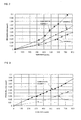
- Fig 2 is a graphic presentation showing the relationship between flow rate and pressure loss in the Examples in the case where the warp pitch/weft pitch ratio was changed,
- Fig 3 is a graphic presentation showing the relationship between flow rate and pressure loss in an Example in the case where the warp diameter/weft diameter ratio was changed;
- Fig 4 is a graphic presentation showing the relationship between flow rate and pressure loss in Example 4 and Comparative Example 5, and
- Fig 5 is a graphic presentation showing the relationship between flow rate and pressure loss in Example 5 and Comparative Example 6
-
-
- 1 : warp
- 2 : weft
- L1 : warp pitch
- L2 : weft pitch
- D1 : warp diameter
- D2 : weft diameter
-
- The present invention is described in detail below by reference to the accompanying drawings.
- Fig. 1A is a front view showing one example of the feed-side passage materials in the spiral separation membrane element according to the present invention, and Fig 1B is a side view showing one example of the feed-side passage materials in the spiral separation membrane element according to the present invention.
- The spiral separation membrane elements of the present invention have a structure comprising a perforated cored central tube and, wound therearound, one or more separation membranes, one or more feed-side passage materials, and one or more permeation-side passage materials This type of membrane elements is described in detail in JP-A-11-235520, JP-A-2000-000437, JP-A-2000-042378 and JP-A-05-168869 With respect to components other than the feed-side passage materials, any conventional separation membranes, permeation-side passage materials, cored central tubes, and the like can be used For example, in the case where two or more feed-side passage materials and two or more permeation-side passage materials are used. the membrane element has a structure in which two or more membrane leaves have been wound around a cored central tube
- In one embodiment of the present invention, the feed-side passage materials have
warps 1 extending almost parallel with the flow of a feed liquid andwefts 2 which are thinner than thewarps 1, and the ratio of the warp pitch to the weft pitch (L1/L2) is preferably 1/1.5 to 1/6, and more preferably 1/3 to 1/5. In case where the weft pitch is larger than the upper limit in that range, the feed-side passage material tends to have a reduced strength, making it difficult to stably maintain a passage. Problems such as the increase in resistance caused when the suspended ingredients present in a feed liquid are caught by the feed-side passage material and a problem concerning a diminution of pressure loss in the feed-side passage can be eliminated by thus reducing the number ofwefts 2 crossing the direction of flow of a feed liquid. - Namely, in conventional membrane elements, the weft pitch L2 is 3-4 mm and a feed liquid meets 250-330
wefts 2 when it passes through one element having a length of about 1 m. However, by increasing the conventional weft pitch fourfold, i e., to 16 mm, the number of wefts can be reduced to 70. Although the pressure loss in the feed-side passage material is not proportional to the number of wefts, to reduce the number thereof is highly effective Furthermore, the accumulation of suspended ingredients present in a feed liquid on the feed-side passage material and on the membrane surface in a filtration step is unavoidable However, this accumulation can be diminished by increasing the weft pitch L2 and thereby reducing the number of wefts and improving suitability for discharge in a back washing step. - From the standpoints of the stability of passage material nets (when they are made of polypropylene and polyethylene) and the degree of reduction in pressure loss (about 50% from the value for conventional passage materials), the weft pitch L2 is most preferably about 16 mm when the warp pitch L1 is 4 mm Namely, the ratio of the warp pitch to the weft pitch is most preferably about 1:4
- Specific numerical ranges are as follows The warp pitch L1 is preferably 2.5-5.0 mm and the weft pitch L2 is preferably 10-20 mm
- The spiral separation membrane elements of the invention can be utilized in any filtration techniques such as reverse osmosis filtration, ultrafiltration, and microfiltration. However, the feed-side passage materials described above exhibit their effects especially when used mainly for clarification.
- Examples of the material of the feed-side passage materials include resins such as polypropylene, polyethylene, poly(ethylene terephthalate) (PET), and polyamides, natural polymers, and rubbers. However, resins are preferably used.
- The
warps 1 and thewefts 2 may be multifilament yarns or monofilament yarns. However, monofilament yarns are preferred because they are difficult to constitute an obstacle to the passage. Thewarps 1 may have been fixed to thewefts 2 by fusion bonding, adhesion, etc., or the feed-side passage materials may be woven fabrics. It is, however, preferred that the passage materials be ones in which thewarps 1 have been fixed to thewefts 2, from the standpoint of stably maintaining the passage - Furthermore, a
warp 1/weft 2 intersection angle may be, for example, 0-80° However, from the standpoint of diminishing the flow resistance caused by thewefts 2, the angle is preferably 30-70°, and more preferably 45-60° The arrangement ofwarps 1 andwefts 2 is preferably such that all thewefts 2 are disposed on one side of thewarps 1 arranged, as shown in Fig 1B This structure has the effect of reducing the resistance of the feed-side passage material - On the other hand, the feed-side passage materials, which have warps extending almost parallel with the direction of flow of a feed liquid and wefts which are thinner than the warps, preferably have a warp diameter/weft diameter ratio (D1/D2) of 2.5/1 or smaller, especially 1.1/1 to 2.3/1 By thus regulating the diameter D2 of the wefts to such a small value, the same effect as described above is obtained even when the cross-sectional area of the feed-liquid passage is increased
- Namely, in conventional membrane elements, the
wefts 2 have the same diameter as thewarps 1 and the passage cross-sectional area for the feed-side passage materials is small for the large thickness t of the passage materials By usingthinner wefts 2 and usingthicker warps 1 while maintaining the same passage material thickness t, the passage material can be made to have a larger passage cross-sectional area. In conventional passage materials having a thickness of 0.8 mm, the diameter of thewarps 1 and that of thewefts 2 are about 0 45 mm because thewarps 1 have the same diameter as thewefts 2 When the ratio of the warp diameter to the weft diameter (D1/D2) is 2:1 and the passage material thickness is 0 8 mm, then the diameter of the warps and that of the wefts are about 0.6 mm and about 0 3 mm, respectively Although this passage material has the same thickness as the conventional ones, the warp diameter therein is 1.33 times the warp diameter in the conventional ones; the warp diameter is the substantial passage material thickness when the weft pitch is long In applications where suspended ingredients of 100-200 µm are removed, the relationship between the warp diameter and the weft diameter influences the accumulation of suspended matters on the passage material - From the standpoint of the stability of passage material nets (when they are made of polypropylene and polyethylene) and the degree of reduction in pressure loss (about 50% from the value for conventional passage materials), the thickness t of the passage material as measured at warp/weft intersections is preferably 0.5-1 5 mm, and more preferably 0.7-1.1 mm, and the warp diameter/weft diameter ratio (D1/D2) is most preferably about 2/1.
- The present invention is described in more detail by reference to the following Examples specifically showing the constitutions and effects of the present invention, but it should be understood that the invention is not construed as being limited thereto.
- A polypropylene net which had a warp diameter of 0.6 mm, a warp diameter/weft diameter ratio of 2:1, a thickness at the intersection of warp and weft of 0.71 mm, a warp pitch of 4 mm, a warp pitch/weft pitch ratio of 1:2, and a warp/weft intersection angle of 50° was set, as a feed-side passage material for use in the present invention (see Fig. 1), on a parallel flat cell (C10-T; passage width: 35 mm, passage length: 145 mm). Pure water was passed through the cell to measure the flow rate and pressure loss. The results obtained are shown in Fig. 2
- A polypropylene net which had a warp diameter of 0.6 mm, a warp diameter/weft diameter ratio of 2 :1, a thickness at the intersection of warp and weft of 0 71 mm, a warp pitch of 4 mm, a warp pitch/weft pitch ratio of 1:4, and a warp/weft intersection angle of 50° was set, as a feed-side passage material for use in the present invention (see Fig. 1), on a parallel flat cell (C10-T, passage width 35 mm, passage length: 145 mm) Pure water was passed through the cell to measure the flow rate and pressure loss. The results obtained are shown in Fig. 2
- A polypropylene net which had a warp diameter of 0 6 mm, a warp diameter/weft diameter ratio of 2:1, a thickness at the intersection of warp and weft of 0.71 mm, a warp pitch of 4 mm, a warp pitch/weft pitch ratio of 1:1, and a warp/weft intersection angle of 50° was set on a parallel flat cell (C10-T, passage width. 35 mm, passage length 145 mm) Pure water was passed through the cell to measure the flow rate and pressure loss The results obtained are shown in Fig. 2
- A polypropylene net which had a warp diameter of 0.6 mm, a warp diameter/weft diameter ratio of 2:1, a thickness at the intersection of warp and weft of 0.71 mm, a warp pitch of 4 mm, a warp pitch/weft pitch ratio of 1:8, and a warp/weft intersection angle of 50° showed a strength insufficient for use as a passage material. As a result, this net could not retain its shape Because of this, a stable measurement of pressure loss as in Examples 1 and 2 was impossible
- As shown in Fig. 2, the passage materials of Examples 1 and 2 could attain a pressure loss reduced to about a half of that for the conventional passage material shown in Comparative Example 1.
- A polypropylene net which had a warp diameter of 0.6 mm, a warp diameter/weft diameter ratio of 2:1, a thickness at the intersection of warp and weft of 0.71 mm, a warp pitch of 4 mm, a warp pitch/weft pitch ratio of 1:4, and a warp/weft intersection angle of 50° was set, as a feed-side passage material for use in the present invention (see Fig. 1), on a parallel flat cell (C10-T, passage width 35 mm, passage length 145 mm). Pure water was passed through the cell to measure the flow rate and pressure loss. The results obtained are shown in Fig 3
- A polypropylene net which had a warp diameter of 0.3 mm, a warp diameter/weft diameter ratio of 1:2, a thickness at the intersection of warp and weft of 0.71 mm, a warp pitch of 4 mm, a warp pitch/weft pitch ratio of 1:4, and a warp/weft intersection angle of 50° was set on a parallel flat cell (C10-T, passage width: 35 mm, passage length: 145 mm). Pure water was passed through the cell to measure the flow rate and pressure loss The results obtained are shown in Fig 3
- A polypropylene net which had a warp diameter of 0.6 mm, a warp diameter/weft diameter ratio of 3:1, a thickness at the intersection of warp and weft of 0.7 mm, a warp pitch of 4 mm, a warp pitch/weft pitch ratio of 1:4, and a warp/weft intersection angle of 50° showed a strength insufficient for use as a passage material. As a result, this net could not retain its shape Because of this, a stable measurement of pressure loss as in Example 1 was impossible
- A polyethylene net which had a warp diameter of 0.6 mm, a warp diameter/weft diameter ratio of 1.7:1, a thickness at the intersection of warp and weft of 0.73 mm, a warp pitch of 4 mm, a warp pitch/weft pitch ratio of 1:4, and a warp/weft intersection angle of 56° was used, as a feed-side passage material for use in the invention (see Fig. 1), to produce a spiral separation membrane element having a diameter of 20 cm and an overall length of 1 m. Pure water was passed on the feed side of this separation membrane element to measure the flow rate and the inlet/outlet pressure loss In this test, a valve disposed in the line of the perforated cored central tube was closed in order to prevent the pure water from flowing into the permeation side The results obtained are shown in Fig 4.
- A polypropylene net which had a warp diameter of 0.6 mm, a warp diameter/weft diameter ratio of 2:1, a thickness at the intersection of warp and weft of 0.71 mm, a warp pitch of 4 mm, a warp pitch/weft pitch ratio of 1:1, and a warp/weft intersection angle of 50° was used to produce a spiral separation membrane element having a diameter of 20 cm and an overall length of 1 m Pure water was passed on the feed side of this separation membrane element to measure the flow rate and the inlet/outlet pressure loss. In this test, a valve disposed in the line of the perforated cored central tube was closed in order to prevent the pure water from flowing into the permeation side. The results obtained are shown in Fig. 4.
- Comparison between Example 4 and Comparative Example 5 shows that also in the actual spiral separation membrane element, the feed-side passage material of Example 4 is more effective in reducing the pressure loss than the feed-side passage material of Comparative Example 5.
- A polyethylene net which had a warp diameter of 0.6 mm, a warp diameter/weft diameter ratio of 1.7:1, a thickness at the intersection of warp and weft of 0.73 mm, a warp pitch of 4 mm, a warp pitch/weft pitch ratio of 1:4, and a warp/weft intersection angle of 56° was used, as a feed-side passage material for use in the invention (see Fig. 1), to produce a spiral separation membrane element having a diameter of 20 cm and an overall length of 1 m. This separation membrane element was operated for full filtration using well water as feed water The well water had a turbidity of about 9 NTU and the filtration rate was 2.5 m3/h. Every 20 minutes, cleaning and flushing were conducted once The difference between the feed-side inlet pressure and the filtration-side pressure in the spiral separation membrane element in this operation was determined The results obtained are shown in Fig. 5
- A polypropylene net which had a warp diameter of 0.6 mm, a warp diameter/weft diameter ratio of 2:1, a thickness at the intersection of warp and weft of 0.71 mm, a warp pitch of 4 mm, a warp pitch/weft pitch ratio of 1:1, and a warp/weft intersection angle of 50° was used to produce a spiral separation membrane element having a diameter of 20 cm and an overall length of 1 m This separation membrane element was operated for full filtration using well water as feed water. The well water had a turbidity of about 9 NTU and the filtration rate was 2.5 m3/h. Every 20 minutes, cleaning and flushing were conducted once The difference between the feed-side inlet pressure and the filtration-side pressure in the spiral separation membrane element in this operation was determined. The results obtained are shown in Fig. 5.
- In the separation membrane element of Comparative Example 6, suspended ingredients were caught by the feed-side passage material at the feed-water inlet and thus constituted a resistance to heighten the feed pressure, resulting in an increased differential pressure in the filtration. In contrast, in the separation membrane element of Example 5, the feed-side passage material had a low passage resistance and, hence, suspended ingredients did not stagnate at the feed-water inlet. Consequently, no increase in feed-water inlet pressure occurred in the separation membrane element of Example 5. It could be seen from the above comparison that the feed-side passage material according to the invention is effective
- It should further be apparent to those skilled in the art that various changes in form and detail of the invention as shown and described above may be made It is intended that such changes be included within the spirit and scope of the claims appended hereto.
- This application is based on Japanese Patent Application No 2003-078129 filed March 30, 2003, the disclosure of which is incorporated herein by reference in its entirety.
Claims (14)
- A spiral separation membrane element which comprises a perforated cored central tube and, wound therearound, one or more separation membranes, one or more feed-side passage materials, and one or more permeation-side passage materials, wherein the feed-side passage materials each have warps extending almost parallel with the direction of flow of a feed liquid and wefts which are thinner than the warps, and a ratio of a pitch of the warps to a pitch of the wefts is 1/1.5 to 1/6
- The spiral separation membrane element as claimed in claim 1, wherein a ratio of the warp diameter to the weft diameter in the feed-side passage materials is 2.5/1 or smaller.
- The spiral separation membrane element as claimed in claim 1, wherein the ratio of a pitch of the warps to a pitch of the wefts is 1/3 to 1/5
- The spiral separation membrane element as claimed in claim 1, wherein the warp pitch is 2.5-5 mm, and the weft pitch is 10-20 mm
- The spiral separation membrane element as claimed in claim 1, wherein the warp/weft intersection angle is 0-80°
- The spiral separation membrane element as claimed in claim 5, wherein the angle is 30-70°.
- The spiral separation membrane element as claimed in claim 2, wherein the ratio is 1.1/1 to 2.3/1.
- The spiral separation membrane element as claimed in claim 1, wherein the passage material has a thickness of 0.5-1.5 mm at a warp/weft intersection.
- A spiral separation membrane element which comprises a perforated cored central tube and, wound therearound, one or more separation membranes, one or more feed-side passage materials, and one or more permeation-side passage materials, wherein the feed-side passage materials each have warps extending almost parallel with the direction of flow of a feed liquid and wefts which are thinner than the warps, and a ratio of the warp diameter to the weft diameter is 2.5/1 or smaller
- The spiral separation membrane element as claimed in claim 9, wherein the warp pitch is 2.5-5 mm, and the weft pitch is 10-20 mm
- The spiral separation membrane element as claimed in claim 9, wherein the warp/weft intersection angle is 0-80°
- The spiral separation membrane element as claimed in claim 11, wherein the angle is 30-70°.
- The spiral separation membrane element as claimed in claim 9, wherein the ratio is 1.1/1 to 2.3/1
- The spiral separation membrane element as claimed in claim 9, wherein the passage material has a thickness of 0.5-1.5 mm at a warp/weft intersection
Applications Claiming Priority (2)
| Application Number | Priority Date | Filing Date | Title |
|---|---|---|---|
| JP2003078129A JP2004283708A (en) | 2003-03-20 | 2003-03-20 | Spiral type separation membrane element |
| JP2003078129 | 2003-03-20 |
Publications (1)
| Publication Number | Publication Date |
|---|---|
| EP1464377A1 true EP1464377A1 (en) | 2004-10-06 |
Family
ID=32844575
Family Applications (1)
| Application Number | Title | Priority Date | Filing Date |
|---|---|---|---|
| EP04006395A Withdrawn EP1464377A1 (en) | 2003-03-20 | 2004-03-17 | Spiral separation membrane element |
Country Status (5)
| Country | Link |
|---|---|
| US (1) | US20040182774A1 (en) |
| EP (1) | EP1464377A1 (en) |
| JP (1) | JP2004283708A (en) |
| KR (1) | KR20040082997A (en) |
| CN (1) | CN1329105C (en) |
Cited By (1)
| Publication number | Priority date | Publication date | Assignee | Title |
|---|---|---|---|---|
| EP4039357A4 (en) * | 2019-10-02 | 2022-11-16 | LG Chem, Ltd. | INTAKE SIDE SPACER AND SEPARATOR DIAPHRAGM ELEMENT |
Families Citing this family (20)
| Publication number | Priority date | Publication date | Assignee | Title |
|---|---|---|---|---|
| DE20311945U1 (en) * | 2003-08-02 | 2004-12-09 | Haver & Boecker | Plate-shaped filter element |
| JP4688140B2 (en) * | 2004-03-26 | 2011-05-25 | 日東電工株式会社 | Spiral type separation membrane element |
| KR101107530B1 (en) | 2004-03-26 | 2012-01-31 | 닛토덴코 가부시키가이샤 | Spiral type separation membrane element |
| JP4587937B2 (en) | 2005-10-31 | 2010-11-24 | 日東電工株式会社 | Spiral type separation membrane element |
| US7998348B2 (en) | 2006-03-09 | 2011-08-16 | Nitto Denko Corporation | Spiral membrane element and process for producing the same |
| WO2007105619A1 (en) * | 2006-03-13 | 2007-09-20 | Nitto Denko Corporation | Spiral-type film element |
| JP5204994B2 (en) | 2007-06-11 | 2013-06-05 | 日東電工株式会社 | Spiral type membrane element and manufacturing method thereof |
| JP5652901B2 (en) * | 2008-03-07 | 2015-01-14 | 住友電気工業株式会社 | Separation membrane module for filtration and filtration apparatus using the separation membrane module |
| US20130146540A1 (en) * | 2011-12-09 | 2013-06-13 | General Electric Company | System and process for treating water and spiral wound membrane element |
| US20130146532A1 (en) | 2011-12-09 | 2013-06-13 | General Electric Company | Feed spacer for spiral wound membrane element |
| ES2674071T3 (en) * | 2012-06-26 | 2018-06-27 | Conwed Plastics Llc | Membrane filtration using a low energy food spacer |
| CN106170332B (en) | 2014-03-31 | 2020-03-10 | 陶氏环球技术有限责任公司 | Helically wound membrane module with defined flow resistance section within the feed spacer |
| KR101606049B1 (en) * | 2015-07-29 | 2016-03-24 | 신흥정공(주) | Centrifugal filter including stereoscopic filter |
| ES2777829T3 (en) | 2015-07-29 | 2020-08-06 | Ddp Specialty Electronic Mat Us Inc | Filter assembly including spiral membrane module and brine seal |
| CN108025261B (en) | 2015-09-30 | 2021-10-29 | Ddp特种电子材料美国有限责任公司 | Filter assembly including spiral wound module, brine seal and end cap |
| WO2017175137A1 (en) | 2016-04-05 | 2017-10-12 | King Abdullah University Of Science And Technology | Fouling resistant membrane spacers |
| JP6353957B2 (en) | 2016-11-18 | 2018-07-04 | 日東電工株式会社 | Raw water channel spacer and spiral membrane element provided with the same |
| KR102230979B1 (en) * | 2017-12-12 | 2021-03-23 | 주식회사 엘지화학 | Feed spacer and reverse osmosis filter module for water treatment comprising the same |
| WO2019117479A1 (en) * | 2017-12-12 | 2019-06-20 | 주식회사 엘지화학 | Feed spacer and reverse osmosis filter module including same |
| KR102875412B1 (en) | 2021-02-16 | 2025-10-22 | 주식회사 엘지화학 | Three-layered feed spacer and reverse osmosis filter module for water treatment comprising the same |
Citations (7)
| Publication number | Priority date | Publication date | Assignee | Title |
|---|---|---|---|---|
| US4022692A (en) * | 1975-08-01 | 1977-05-10 | Erika, Inc. | Non-woven support screen for mass transfer devices |
| EP0053392A2 (en) * | 1980-12-03 | 1982-06-09 | SECON Gesellschaft für Separations- und Concentrationstechnick mbH | Dialyser with semi-permeable tubing sections stacked one atop the other |
| EP0347174A1 (en) * | 1988-06-14 | 1989-12-20 | Desalination Systems Inc. | Improved spiral wound membrane cartridge and method of treatment |
| EP0382488A2 (en) * | 1989-02-08 | 1990-08-16 | Koch Membrane Systems, Inc | Spiral membrane module with improved feed spacer |
| JPH05168869A (en) * | 1991-12-18 | 1993-07-02 | Nitto Denko Corp | Spiral separation membrane module |
| JPH10309445A (en) * | 1997-05-12 | 1998-11-24 | Nitto Denko Corp | Spiral type membrane module |
| JPH11197469A (en) * | 1998-01-16 | 1999-07-27 | Nitto Denko Corp | Spiral type membrane module |
Family Cites Families (2)
| Publication number | Priority date | Publication date | Assignee | Title |
|---|---|---|---|---|
| WO1999065594A1 (en) * | 1998-06-18 | 1999-12-23 | Toray Industries, Inc. | Spiral reverse osmosis membrane element, reverse osmosis membrane module using it, device and method for reverse osmosis separation incorporating the module |
| JP2000042378A (en) * | 1999-08-20 | 2000-02-15 | Toray Ind Inc | Fluid separation element |
-
2003
- 2003-03-20 JP JP2003078129A patent/JP2004283708A/en active Pending
-
2004
- 2004-03-17 EP EP04006395A patent/EP1464377A1/en not_active Withdrawn
- 2004-03-18 US US10/802,884 patent/US20040182774A1/en not_active Abandoned
- 2004-03-19 KR KR1020040018857A patent/KR20040082997A/en not_active Withdrawn
- 2004-03-22 CN CNB2004100302050A patent/CN1329105C/en not_active Expired - Fee Related
Patent Citations (7)
| Publication number | Priority date | Publication date | Assignee | Title |
|---|---|---|---|---|
| US4022692A (en) * | 1975-08-01 | 1977-05-10 | Erika, Inc. | Non-woven support screen for mass transfer devices |
| EP0053392A2 (en) * | 1980-12-03 | 1982-06-09 | SECON Gesellschaft für Separations- und Concentrationstechnick mbH | Dialyser with semi-permeable tubing sections stacked one atop the other |
| EP0347174A1 (en) * | 1988-06-14 | 1989-12-20 | Desalination Systems Inc. | Improved spiral wound membrane cartridge and method of treatment |
| EP0382488A2 (en) * | 1989-02-08 | 1990-08-16 | Koch Membrane Systems, Inc | Spiral membrane module with improved feed spacer |
| JPH05168869A (en) * | 1991-12-18 | 1993-07-02 | Nitto Denko Corp | Spiral separation membrane module |
| JPH10309445A (en) * | 1997-05-12 | 1998-11-24 | Nitto Denko Corp | Spiral type membrane module |
| JPH11197469A (en) * | 1998-01-16 | 1999-07-27 | Nitto Denko Corp | Spiral type membrane module |
Non-Patent Citations (3)
| Title |
|---|
| PATENT ABSTRACTS OF JAPAN vol. 017, no. 577 (C - 1122) 20 October 1993 (1993-10-20) * |
| PATENT ABSTRACTS OF JAPAN vol. 1999, no. 02 26 February 1999 (1999-02-26) * |
| PATENT ABSTRACTS OF JAPAN vol. 1999, no. 12 29 October 1999 (1999-10-29) * |
Cited By (2)
| Publication number | Priority date | Publication date | Assignee | Title |
|---|---|---|---|---|
| EP4039357A4 (en) * | 2019-10-02 | 2022-11-16 | LG Chem, Ltd. | INTAKE SIDE SPACER AND SEPARATOR DIAPHRAGM ELEMENT |
| US12427483B2 (en) | 2019-10-02 | 2025-09-30 | Lg Chem, Ltd. | Feed side spacer and separation membrane element |
Also Published As
| Publication number | Publication date |
|---|---|
| US20040182774A1 (en) | 2004-09-23 |
| CN1533826A (en) | 2004-10-06 |
| JP2004283708A (en) | 2004-10-14 |
| CN1329105C (en) | 2007-08-01 |
| KR20040082997A (en) | 2004-09-30 |
Similar Documents
| Publication | Publication Date | Title |
|---|---|---|
| US20040182774A1 (en) | Spiral separation membrane element | |
| US6190556B1 (en) | Desalination method and apparatus utilizing nanofiltration and reverse osmosis membranes | |
| JP4650921B2 (en) | Spiral type separation membrane element | |
| KR102009550B1 (en) | Multi-stage reverse osmosis membrane device, and operation method therefor | |
| JP4251879B2 (en) | Operation method of separation membrane module | |
| KR20090071556A (en) | Hollow fiber membrane module | |
| CN113694585B (en) | Tangential flow filter assembly, tangential flow filter device and perfusion system | |
| JP2004050005A (en) | Spiral membrane element, reverse osmosis membrane module, and reverse osmosis membrane apparatus | |
| AU606463B2 (en) | Membrane separation apparatus and method | |
| JP2000237554A (en) | Spiral type membrane element | |
| US20210394120A1 (en) | Spacer with mixing elements, particularly for membrane modules | |
| JP2000042378A (en) | Fluid separation element | |
| CN110314549B (en) | Rolling type membrane element, rolling type membrane filter element and rolling type membrane column | |
| EP0045663A2 (en) | Spiral-wrapped reverse osmosis membrane assembly | |
| EP1464378A1 (en) | Spiral separation membrane element | |
| RU2199377C1 (en) | Membrane plant for separation of solutions | |
| JP2009050759A (en) | Spiral type separation membrane element | |
| CN100462130C (en) | Helically wound separator membrane elements | |
| JP2025538287A (en) | Synthetic monofilament open mesh filter fabric with asymmetric structure for liquid/solid filtration with low pressure drop and easy regeneration | |
| JPH09299770A (en) | Spiral type membrane element | |
| JP4107724B2 (en) | Spiral membrane element | |
| JP2005319454A (en) | Spiral type separation membrane element | |
| JP4488402B2 (en) | Hollow fiber membrane module | |
| JPH09299768A (en) | Hollow fiber membrane module | |
| JPH0747112B2 (en) | Spiral type liquid separation element |
Legal Events
| Date | Code | Title | Description |
|---|---|---|---|
| PUAI | Public reference made under article 153(3) epc to a published international application that has entered the european phase |
Free format text: ORIGINAL CODE: 0009012 |
|
| AK | Designated contracting states |
Kind code of ref document: A1 Designated state(s): AT BE BG CH CY CZ DE DK EE ES FI FR GB GR HU IE IT LI LU MC NL PL PT RO SE SI SK TR |
|
| AX | Request for extension of the european patent |
Extension state: AL LT LV MK |
|
| AKX | Designation fees paid | ||
| REG | Reference to a national code |
Ref country code: DE Ref legal event code: 8566 |
|
| STAA | Information on the status of an ep patent application or granted ep patent |
Free format text: STATUS: THE APPLICATION IS DEEMED TO BE WITHDRAWN |
|
| 18D | Application deemed to be withdrawn |
Effective date: 20050407 |