EP1464361A1 - Multi-chamber pacing system - Google Patents
Multi-chamber pacing system Download PDFInfo
- Publication number
- EP1464361A1 EP1464361A1 EP04002880A EP04002880A EP1464361A1 EP 1464361 A1 EP1464361 A1 EP 1464361A1 EP 04002880 A EP04002880 A EP 04002880A EP 04002880 A EP04002880 A EP 04002880A EP 1464361 A1 EP1464361 A1 EP 1464361A1
- Authority
- EP
- European Patent Office
- Prior art keywords
- signal
- blanking interval
- iegm
- pacing
- iegm signal
- Prior art date
- Legal status (The legal status is an assumption and is not a legal conclusion. Google has not performed a legal analysis and makes no representation as to the accuracy of the status listed.)
- Granted
Links
- 230000004044 response Effects 0.000 claims abstract description 39
- 230000000763 evoking effect Effects 0.000 claims abstract description 36
- 210000005242 cardiac chamber Anatomy 0.000 claims abstract description 18
- 238000001514 detection method Methods 0.000 claims abstract description 17
- 238000001914 filtration Methods 0.000 claims description 8
- 238000013213 extrapolation Methods 0.000 claims description 5
- 230000010354 integration Effects 0.000 claims description 4
- 230000000638 stimulation Effects 0.000 description 11
- 238000000034 method Methods 0.000 description 7
- 230000036279 refractory period Effects 0.000 description 5
- 210000004165 myocardium Anatomy 0.000 description 3
- 210000005241 right ventricle Anatomy 0.000 description 3
- 230000003111 delayed effect Effects 0.000 description 2
- 230000009977 dual effect Effects 0.000 description 2
- 210000005245 right atrium Anatomy 0.000 description 2
- 208000033986 Device capturing issue Diseases 0.000 description 1
- 239000008280 blood Substances 0.000 description 1
- 210000004369 blood Anatomy 0.000 description 1
- 230000001934 delay Effects 0.000 description 1
- 238000010586 diagram Methods 0.000 description 1
- 230000005284 excitation Effects 0.000 description 1
- 230000006870 function Effects 0.000 description 1
- 210000002837 heart atrium Anatomy 0.000 description 1
- 210000005246 left atrium Anatomy 0.000 description 1
- 210000005240 left ventricle Anatomy 0.000 description 1
- 238000005259 measurement Methods 0.000 description 1
- 230000028161 membrane depolarization Effects 0.000 description 1
- 230000035945 sensitivity Effects 0.000 description 1
- 230000002861 ventricular Effects 0.000 description 1
Images


Classifications
-
- A—HUMAN NECESSITIES
- A61—MEDICAL OR VETERINARY SCIENCE; HYGIENE
- A61N—ELECTROTHERAPY; MAGNETOTHERAPY; RADIATION THERAPY; ULTRASOUND THERAPY
- A61N1/00—Electrotherapy; Circuits therefor
- A61N1/18—Applying electric currents by contact electrodes
- A61N1/32—Applying electric currents by contact electrodes alternating or intermittent currents
- A61N1/36—Applying electric currents by contact electrodes alternating or intermittent currents for stimulation
- A61N1/362—Heart stimulators
- A61N1/37—Monitoring; Protecting
- A61N1/3702—Physiological parameters
-
- A—HUMAN NECESSITIES
- A61—MEDICAL OR VETERINARY SCIENCE; HYGIENE
- A61N—ELECTROTHERAPY; MAGNETOTHERAPY; RADIATION THERAPY; ULTRASOUND THERAPY
- A61N1/00—Electrotherapy; Circuits therefor
- A61N1/18—Applying electric currents by contact electrodes
- A61N1/32—Applying electric currents by contact electrodes alternating or intermittent currents
- A61N1/36—Applying electric currents by contact electrodes alternating or intermittent currents for stimulation
- A61N1/362—Heart stimulators
- A61N1/365—Heart stimulators controlled by a physiological parameter, e.g. heart potential
- A61N1/368—Heart stimulators controlled by a physiological parameter, e.g. heart potential comprising more than one electrode co-operating with different heart regions
- A61N1/3684—Heart stimulators controlled by a physiological parameter, e.g. heart potential comprising more than one electrode co-operating with different heart regions for stimulating the heart at multiple sites of the ventricle or the atrium
Definitions
- the present invention relates to a multi-chamber pacing system comprising pulse generator means for successively delivering pacing pulses to chambers of a patient's heart, and evoked response detectors having blanking intervals following the delivery of pacing pulses and including sensing elements for sensing IEGM signals from each of said heart chambers and an integrating means adapted to integrate said IEGM signal within evoked response detection time windows after delivery of pacing pulses for detecting evoked response, said evoked response detection time window for a heart chamber containing at least one blanking interval resulting from delivery of a pacing pulse to another chamber, and each of said sensed IEGM signals having a generally known morphology.
- chambers of the heart denotes right and left atria as well as right and left ventricles of the heart.
- US 6,148,234 disclose a dual site pacing system, either bi-ventricular or bi-atrial, wherein signals are sensed during the refractory period following delivery of stimulation pulses.
- Pacing pulses are delivered substantially concurrently to both the heart chambers, although it is mentioned that for patients with an intra-atrial block the left atrium may be stimulated up to 90 msec later than the right atrium. If capture is achieved in both chambers no intrinsic depolarisation signals can be sensed during the following refractory period. If, however, the threshold of either heart chamber has risen above the level of the delivered pulses, that chamber will not be captured and will not have a refractory period following that delivery of the pulses.
- the excitation signal from the other chamber will be sensed in the non-captured chamber during the refractory period.
- Such sensing during the pacemaker refractory period is considered to be the result of loss of capture.
- the purpose of the present invention is to propose an improved technique for detecting evoked response in a reliable way at multi-chamber pacing.
- the idea of the present invention is to reconstruct the integral of the IEGM signal sensed in one heart chamber during blanking intervals resulting from stimulation in other chambers.
- the reconstructed integral will normally differ somewhat from the true integral value without blanking, however, this will result in errors of only minor importance and will not negatively influence the possibility of detecting evoked response on chambers having stimulation blankings.
- the knowledge of the general signal morphology is utilized. To be able to reconstruct the integral the second pacing pulse in a pair of consecutive pacing pulses must not be delivered within the blanking interval following the first pacing pulse.
- the pulse generator means are therefore controlled to deliver the second pacing pulse with a time delay exceeding the length of the blanking interval following the first one of said two consecutive pacing pulses. It should also be noted that with the present invention it is also possible to reconstruct the integral in more than one blanking interval, occurring in an evoked response detection time interval as a result of subsequent stimulations in other chambers of the heart. Such a situation can appear if time delays between the stimulations in different heart chambers are comparatively short.
- the signal reconstructing means is adapted to select among several predetermined ways of reconstructing the IEGM signal in the blanking interval with the aid of the knowledge of the signal morphology.
- knowledge about the signal morphology is utilized for selecting the best way of reconstructing the signals in the blanking interval.
- filtering means are provided to filter the IEGM signal in a filtration time interval of predetermined length to produce a reconstructed signal for use for detection of evoked response, said filtration time interval containing the blanking interval.
- the pacing system comprising an implantable lead having a tip and a ring electrode and the pulse generator means having a case, IEGM signals being measured between the tip electrode and the case and between the ring electrode and the case, respectively, a memory means is provided for storing the IEGM signals, and the integral reconstructing means is adapted to integrate the IEGM signal measured between the tip electrode and the case while using that portion of the stored ring electrode to case IEGM signal which corresponds to the blanking interval in the integrated IEGM signal for the integration within the blanking interval.
- the ring electrode may be floating in blood and the tip electrode is attached to the myocardium and the tip and ring electrodes have different shapes, the signals will look quite similar. Since the ring electrode is further away from myocardium than the tip, the signal resulting from depolarization of myocardium will arrive at the tip electrode before it arrives at the ring electrode. Thus the ring electrode to case signal will be delayed compared to the tip electrode to case signal. If a tip to case signal channel is blanked during the evoked response detection time window, information about the signal in this blanking period can be found in the ring to case signal after a certain time when none of the two signal channels are blanked.
- figure 1 shows a simplified block diagram of an embodiment of the pacing system according to the invention
- figures 2-5 show schematically IEGM signal portions containing a blanking interval for illustrating different reconstructing techniques suitable for use in the pacing system according to the invention
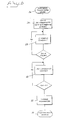
- figure 6 is a flowchart illustrating an example of evoked response signal processing during blanking in the pacing system according to the invention
- figure 7 illustrates still another embodiment of reconstruction in the pacing system according the invention.
- Figure 1 shows schematically a multi-chamber pacing system with leads 42, 44 , 46 having bipolar electrodes 48, 50, 52 implanted in right atrium and in the ventricles of a patient's heart 54.
- the pulse generator case is schematically shown at 56.
- evoked response detector 58 Inside the pulse generator case there are an evoked response detector 58 with IEGM signal sensing means and integral reconstructing means 60 and memory means 62. These components are preferably realized by a microprocessor.
- IEGM signals are sensed and integrated by the evoked response detector 58 in a evoked response detection time window.
- the integral reconstructing means 60 the integral is reconstructed in blanking intervals resulting from delivery of pacing pulses in other heart chambers.
- measured complete IEGM signals are stored, such that the reconstructing means 60 can use that portion of the stored signal which corresponds to the blanking interval.
- a complete IEGM signal can be measured in advance and stored in the memory means 62.
- IEGM signals can alternatively be measured simultaneously between tip electrode, e.g. the tip electrode 64 in the right ventricle and the case 56, and between said ring electrode 66 in the right ventricle, and the case 56.
- the measured IEGM signals are stored in the memory means 62.
- the integral reconstructing means 60 is adapted to integrate the IEGM signal measured between said tip electrode 64 and said case 56 while using that portion of the stored ring electrode 66 to case 56 IEGM signal which corresponds to the blanking interval in the integrated IEGM signal.
- Figure 2 shows qualitatively the simplified appearance of an intracardiac evoked response signal as a function of time following the delivery of a stimulation pulse 2.
- a blanking interval 4 resulting from the delivery of a pacing pulse in another heart chamber, is limited by two vertical dashed lines 6,8 in the figure.
- the blanking time is normally 6-15 msec.
- Figure 3 shows in an enlarged scale a portion of the intracardiac evoked response (ER) signal in figure 2.
- Figure 3 illustrates an example where the ER signal during the blanking interval 4 is mathematically reconstructed by using the instant slope at the starting point 10 of the blanking interval. The reconstructed signal is then used for reconstructing the integral of the signal.
- ER intracardiac evoked response
- Figure 4 shows an example with the blanking interval 12 positioned around a minimum 14 in the intracardiac ER signal.
- the signal is reconstructed in the blanking interval by using the instant slopes of the intracardiac ER signal at the beginning 16 and end 18 of the blanking interval 12 for linear extrapolations of the signal forwardly from the beginning 16 of the blanking interval 12 and rearwardbly from the end 18 of the blanking interval respectively.
- This linear extrapolations meet in an intersection point 20, thus forming a reconstructed signal in the blanking interval 12.
- the reconstructed signal is then used for reconstructing the integral of the signal.
- the intracardiac evoked response signal can be reconstructed or replaced during blanking by a constant signal level u 0 , e.g. equal to the mean value of the signal values u 1 and u 2 at the ends of the blanking interval 22, see figure 5.
- the signal can be reconstructed by applying a polynomial of suitable degree to the signal by using a plurality of IEGM signal samples preceding and succeeding the blanking interval.
- the ER signal is smoothly varying with time without any discontinuities, and the general morphology or progress of the signal in the evoked response detection time interval can e.g. be determined in advance by introductory measurements and memorized for the subsequent use, cf. the description of figure 1 above.
- Figure 6 is a flow chart illustrating an example of signal processing during blanking in the pacing system according to the invention. It is supposed that the evoked response signal processing occurs in e.g. a microprocessor controlled signal process known in the art. The example relates to normal autocapture signal processing just interrupted during blanking caused by stimulation in the heart chamber opposite to the considered chamber. The process disclosed in figure 6 will replace the process, which would otherwise occur in autocapture signal processing if no blanking had occurred.
- the input to the flow chart in figure 6 is the intracardiac evoked response signal integrated up to the beginning of the blanking interval or blanking point.
- the flow chart then illustrates the signal processing up to the end of the blanking interval whereafter the integrated evoked response signal is further processed in the normal, well-known way for evoked response detection.
- VBLNK see 24 in figure 6, denotes ventricular blanking.
- Cnt in box 26 in figure 6 denotes counter value, and U int denotes integrated ER signal.
- Box 30 illustrates the addition of the integrated value of estimated mean value of the signal during VBLNK to the integrated ER signal U int up to the beginning of VBLNK.
- the resulting evoke response signal U evoked response box 32, is then further processed, at 34, for evoked response detection according to well-known technique.
- the value of the filter coefficients immediately preceding and immediately succeeding the blanking period is equal to 1 + n/2, where n is the number of samples being blanked.
Landscapes
- Health & Medical Sciences (AREA)
- Cardiology (AREA)
- Heart & Thoracic Surgery (AREA)
- Life Sciences & Earth Sciences (AREA)
- Biophysics (AREA)
- Physiology (AREA)
- Engineering & Computer Science (AREA)
- Biomedical Technology (AREA)
- Nuclear Medicine, Radiotherapy & Molecular Imaging (AREA)
- Radiology & Medical Imaging (AREA)
- Animal Behavior & Ethology (AREA)
- General Health & Medical Sciences (AREA)
- Public Health (AREA)
- Veterinary Medicine (AREA)
- Electrotherapy Devices (AREA)
Abstract
Description
- The present invention relates to a multi-chamber pacing system comprising pulse generator means for successively delivering pacing pulses to chambers of a patient's heart, and evoked response detectors having blanking intervals following the delivery of pacing pulses and including sensing elements for sensing IEGM signals from each of said heart chambers and an integrating means adapted to integrate said IEGM signal within evoked response detection time windows after delivery of pacing pulses for detecting evoked response, said evoked response detection time window for a heart chamber containing at least one blanking interval resulting from delivery of a pacing pulse to another chamber, and each of said sensed IEGM signals having a generally known morphology.
- In the following the expression chambers of the heart denotes right and left atria as well as right and left ventricles of the heart.
- US 6,148,234 disclose a dual site pacing system, either bi-ventricular or bi-atrial, wherein signals are sensed during the refractory period following delivery of stimulation pulses. Pacing pulses are delivered substantially concurrently to both the heart chambers, although it is mentioned that for patients with an intra-atrial block the left atrium may be stimulated up to 90 msec later than the right atrium. If capture is achieved in both chambers no intrinsic depolarisation signals can be sensed during the following refractory period. If, however, the threshold of either heart chamber has risen above the level of the delivered pulses, that chamber will not be captured and will not have a refractory period following that delivery of the pulses. In this case, for patient's having a conduction delay from one chamber to the other, the excitation signal from the other chamber will be sensed in the non-captured chamber during the refractory period. Such sensing during the pacemaker refractory period is considered to be the result of loss of capture.
- If two heart chambers are stimulated at somewhat different times, one of the chambers will be blanked when the other one is stimulated. Most pacing systems are constructed such that all signal channels are blanked when a stimulation pulse is sent. There will consequently be an interruption in sensed IEGM signals and corresponding evoked response signals obtained by integration of the IEGM signals. This occurs in all dual or multi chamber pacing systems, e.g. at both bi-ventricular and bi-atrial pacing. If sensed signals are integrated in an evoked response detection time interval from e.g. 4 msec to 50 msec after stimulation to determine evoked response, and if a stimulation of the other chamber takes place at 10 msec after the first stimulation there will be an interruption of the signal in the above mentioned detection time interval.
- The purpose of the present invention is to propose an improved technique for detecting evoked response in a reliable way at multi-chamber pacing.
- This purpose is obtained by a pacing system of the kind defined in the introductory portion and having the characterizing feature of
claim 1. - Thus, the idea of the present invention is to reconstruct the integral of the IEGM signal sensed in one heart chamber during blanking intervals resulting from stimulation in other chambers. The reconstructed integral will normally differ somewhat from the true integral value without blanking, however, this will result in errors of only minor importance and will not negatively influence the possibility of detecting evoked response on chambers having stimulation blankings. When reconstructing the integral of the signal the knowledge of the general signal morphology is utilized. To be able to reconstruct the integral the second pacing pulse in a pair of consecutive pacing pulses must not be delivered within the blanking interval following the first pacing pulse. The pulse generator means are therefore controlled to deliver the second pacing pulse with a time delay exceeding the length of the blanking interval following the first one of said two consecutive pacing pulses. It should also be noted that with the present invention it is also possible to reconstruct the integral in more than one blanking interval, occurring in an evoked response detection time interval as a result of subsequent stimulations in other chambers of the heart. Such a situation can appear if time delays between the stimulations in different heart chambers are comparatively short.
- According to an advantageous embodiment of the pacing system according to the invention the signal reconstructing means is adapted to select among several predetermined ways of reconstructing the IEGM signal in the blanking interval with the aid of the knowledge of the signal morphology. Thus in this way knowledge about the signal morphology is utilized for selecting the best way of reconstructing the signals in the blanking interval.
- If a constant signal level u0 equal to the mean value of the sensed IEGM signal values at the beginning u1 and at the end u2 of the blanking interval is integrated during the blanking interval the result may be somewhat noise sensitive, since it depends only the two samples u1 and u2. To reduce this noise sensitivity, according to still another advantageous embodiment of the pacing system according to the invention, filtering means are provided to filter the IEGM signal in a filtration time interval of predetermined length to produce a reconstructed signal for use for detection of evoked response, said filtration time interval containing the blanking interval.
- According to still another advantageous embodiment of the pacing system according to the invention with the pacing system comprising an implantable lead having a tip and a ring electrode and the pulse generator means having a case, IEGM signals being measured between the tip electrode and the case and between the ring electrode and the case, respectively, a memory means is provided for storing the IEGM signals, and the integral reconstructing means is adapted to integrate the IEGM signal measured between the tip electrode and the case while using that portion of the stored ring electrode to case IEGM signal which corresponds to the blanking interval in the integrated IEGM signal for the integration within the blanking interval. Even though the ring electrode may be floating in blood and the tip electrode is attached to the myocardium and the tip and ring electrodes have different shapes, the signals will look quite similar. Since the ring electrode is further away from myocardium than the tip, the signal resulting from depolarization of myocardium will arrive at the tip electrode before it arrives at the ring electrode. Thus the ring electrode to case signal will be delayed compared to the tip electrode to case signal. If a tip to case signal channel is blanked during the evoked response detection time window, information about the signal in this blanking period can be found in the ring to case signal after a certain time when none of the two signal channels are blanked.
- To explain the invention in greater detail embodiments of the pacing system according to the invention will be described below with reference to the accompanying drawings on which figure 1 shows a simplified block diagram of an embodiment of the pacing system according to the invention, figures 2-5 show schematically IEGM signal portions containing a blanking interval for illustrating different reconstructing techniques suitable for use in the pacing system according to the invention, figure 6 is a flowchart illustrating an example of evoked response signal processing during blanking in the pacing system according to the invention, and figure 7 illustrates still another embodiment of reconstruction in the pacing system according the invention.
- Figure 1 shows schematically a multi-chamber pacing system with
leads bipolar electrodes heart 54. The pulse generator case is schematically shown at 56. - Inside the pulse generator case there are an evoked
response detector 58 with IEGM signal sensing means and integral reconstructing means 60 and memory means 62. These components are preferably realized by a microprocessor. - IEGM signals are sensed and integrated by the evoked
response detector 58 in a evoked response detection time window. By the integral reconstructing means 60 the integral is reconstructed in blanking intervals resulting from delivery of pacing pulses in other heart chambers. In the memory means measured complete IEGM signals are stored, such that the reconstructingmeans 60 can use that portion of the stored signal which corresponds to the blanking interval. A complete IEGM signal can be measured in advance and stored in the memory means 62. IEGM signals can alternatively be measured simultaneously between tip electrode, e.g. thetip electrode 64 in the right ventricle and thecase 56, and between saidring electrode 66 in the right ventricle, and thecase 56. The measured IEGM signals are stored in the memory means 62. Since the ring to case signal is delayed vis-à-vis the tip to case signal, the integral reconstructingmeans 60 is adapted to integrate the IEGM signal measured between saidtip electrode 64 and saidcase 56 while using that portion of thestored ring electrode 66 tocase 56 IEGM signal which corresponds to the blanking interval in the integrated IEGM signal. - Figure 2 shows qualitatively the simplified appearance of an intracardiac evoked response signal as a function of time following the delivery of a
stimulation pulse 2. Ablanking interval 4, resulting from the delivery of a pacing pulse in another heart chamber, is limited by two verticaldashed lines - Figure 3 shows in an enlarged scale a portion of the intracardiac evoked response (ER) signal in figure 2. Figure 3 illustrates an example where the ER signal during the
blanking interval 4 is mathematically reconstructed by using the instant slope at thestarting point 10 of the blanking interval. The reconstructed signal is then used for reconstructing the integral of the signal. - Figure 4 shows an example with the
blanking interval 12 positioned around a minimum 14 in the intracardiac ER signal. In this embodiment the signal is reconstructed in the blanking interval by using the instant slopes of the intracardiac ER signal at thebeginning 16 andend 18 of theblanking interval 12 for linear extrapolations of the signal forwardly from thebeginning 16 of theblanking interval 12 and rearwardbly from theend 18 of the blanking interval respectively. This linear extrapolations meet in anintersection point 20, thus forming a reconstructed signal in theblanking interval 12. The reconstructed signal is then used for reconstructing the integral of the signal. - As another alternative the intracardiac evoked response signal can be reconstructed or replaced during blanking by a constant signal level u0, e.g. equal to the mean value of the signal values u1 and u2 at the ends of the
blanking interval 22, see figure 5. - Instead of linear approximations of the signal within the blanking period as described above the signal can be reconstructed by applying a polynomial of suitable degree to the signal by using a plurality of IEGM signal samples preceding and succeeding the blanking interval.
- As appears from figures 2-5 the ER signal is smoothly varying with time without any discontinuities, and the general morphology or progress of the signal in the evoked response detection time interval can e.g. be determined in advance by introductory measurements and memorized for the subsequent use, cf. the description of figure 1 above.
- Figure 6 is a flow chart illustrating an example of signal processing during blanking in the pacing system according to the invention. It is supposed that the evoked response signal processing occurs in e.g. a microprocessor controlled signal process known in the art. The example relates to normal autocapture signal processing just interrupted during blanking caused by stimulation in the heart chamber opposite to the considered chamber. The process disclosed in figure 6 will replace the process, which would otherwise occur in autocapture signal processing if no blanking had occurred. The input to the flow chart in figure 6 is the intracardiac evoked response signal integrated up to the beginning of the blanking interval or blanking point. The flow chart then illustrates the signal processing up to the end of the blanking interval whereafter the integrated evoked response signal is further processed in the normal, well-known way for evoked response detection.
- VBLNK, see 24 in figure 6, denotes ventricular blanking. Cnt in
box 26 in figure 6 denotes counter value, and Uint denotes integrated ER signal. - In box 28 Uint is integrated during VBLNK. The counter value equals the count number of loops, viz.the number of samples during VBLNK.
-
Box 30 illustrates the addition of the integrated value of estimated mean value of the signal during VBLNK to the integrated ER signal Uint up to the beginning of VBLNK. - The resulting evoke response signal Uevoked response,
box 32, is then further processed, at 34, for evoked response detection according to well-known technique. - Another way of viewing the procedure illustrated in figure 6 is to see the samples in the ER window as a mathematical vector. By taking the dot product of this vector and the vector whose samples are depicted in figure 7 Uevoked response is obtained. Given the definition of the product, the value of the integrated linearly interpolated evoked response equalswhere ui are the individual voltage samples in the ER window and fi the (filter) coefficients depicted in figure 7.

- The value of the filter coefficients immediately preceding and immediately succeeding the blanking period is equal to 1 + n/2, where n is the number of samples being blanked.
Claims (12)
- A multi-chamber pacing system comprising pulse generator means for successively delivering pacing pulses to chambers of a patient's heart, and evoked response detectors having blanking intervals following the delivery of pacing pulses and including sensing elements for sensing IEGM signals from each of said heart chambers and an integrating means adapted to integrate said IEGM signal within evoked response detection time windows after delivery of pacing pulses for detecting evoked response, said evoked response detection time window for a heart chamber containing at least one blanking interval resulting from delivery of a pacing pulse to another chamber and each of said sensed IEGM signal having a generally known morphology, characterized in that an integral reconstructing means is provided to reconstruct the time integral of said IEGM signal from one of said heart chambers in the blanking interval following delivery of a pacing pulse to another heart chamber.
- The pacing system according to claim 1, characterized in that said integral reconstructing means is adapted to integrate a constant IEGM signal value derived from the known signal morphology within said blanking interval.
- The pacing system according to claims 1 or 2, characterized in that said integral reconstructing means is adapted to integrate a constant IEGM signal value equal to the mean value of the IEGM signal values at the ends of the blanking interval.
- The pacing system according to claim 1, characterized in that a signal reconstructing means is provided to reconstruct said IEGM signal in the blanking interval, and in that said integral reconstructing means is adapted to integrate said reconstructed IEGM signal within the blanking interval to reconstruct the integral in the blanking interval.
- The pacing system according to claim 4, characterized in that said signal reconstructing means is adapted to select among several predetermined ways of reconstructing said IEGM signal in the blanking interval with the aid of said knowledge of the signal morphology.
- The pacing system according to claims 4 or 5, characterized in that said signal reconstructing means is adapted to reconstruct said IEGM signal within the blanking interval by using the instant slope of the IEGM signal at the beginning of the blanking interval for linear extrapolation of the IEGM signal in the blanking interval.
- The pacing system according to claims 4 or 5, said IEGM signal having a minimum within the blanking interval, characterized in that said signal reconstructing means is adapted to use the instant slopes of said IEGM signal at the beginning and at the end of the blanking interval for linear extrapolation of said IEGM signal forwardly from the beginning of the blanking interval and rearwardly from the end of the blanking interval respectively, till the intersection point of said linear extrapolations.
- The pacing system according to claims 4 or 5, characterized in that said reconstructing means is adapted to reconstruct said IEGM signal within the blanking interval by using a plurality of IEGM signal values preceding and succeeding said blanking interval according to a polynomial of a predetermined degree.
- The pacing system according to claims 4 or 5, characterized in that filtering means are provided to filter said IEGM signal in a filtration time interval of predetermined length to produce a reconstructed signal for use for detection of evoked response, said filtration time interval containing the blanking interval.
- The pacing system according to claim 9, characterized in that said filtering means comprise a FIR filter having filtering coefficients equal to zero within said blanking interval.
- The pacing system according to claim 1, characterized in that a memory means is provided for storing a complete IEGM signal measured in advance in the whole evoked response detection time window without any blanking interval, and in that said integral reconstructing means is adapted to use the stored IEGM signal for the integration within the blanking interval.
- The pacing system according to claim 1, said pacing system comprising at least one implantable lead having a tip and a ring electrode and said pulse generator means having a case, IEGM signals being measured between said tip electrode and said case and between said ring electrode and said case, respecttively, characterized in that a memory means is provided for storing the IEGM signals, and in that said integral reconstructing means is adapted to integrate the IEGM signal measured between said tip electrode and said case while using that portion of the stored ring electrode to case IEGM signal which corresponds to the blanking interval in the integrated IEGM signal for the integration within the blanking interval.
Applications Claiming Priority (2)
| Application Number | Priority Date | Filing Date | Title |
|---|---|---|---|
| SE0300917 | 2003-03-31 | ||
| SE0300917A SE0300917D0 (en) | 2003-03-31 | 2003-03-31 | Multi-chamber pacing system |
Publications (2)
| Publication Number | Publication Date |
|---|---|
| EP1464361A1 true EP1464361A1 (en) | 2004-10-06 |
| EP1464361B1 EP1464361B1 (en) | 2008-07-16 |
Family
ID=20290864
Family Applications (1)
| Application Number | Title | Priority Date | Filing Date |
|---|---|---|---|
| EP04002880A Expired - Lifetime EP1464361B1 (en) | 2003-03-31 | 2004-02-10 | Multi-chamber pacing system |
Country Status (4)
| Country | Link |
|---|---|
| US (1) | US7089058B2 (en) |
| EP (1) | EP1464361B1 (en) |
| DE (1) | DE602004015011D1 (en) |
| SE (1) | SE0300917D0 (en) |
Cited By (1)
| Publication number | Priority date | Publication date | Assignee | Title |
|---|---|---|---|---|
| WO2007081248A1 (en) * | 2006-01-16 | 2007-07-19 | St. Jude Medical Ab | An implantable heart stimulating device and method for evoked response detection |
Families Citing this family (1)
| Publication number | Priority date | Publication date | Assignee | Title |
|---|---|---|---|---|
| US7627517B2 (en) * | 2004-12-09 | 2009-12-01 | Rosenthal Collins Group, Llc | Method and system for providing configurable features for graphical user interfaces for electronic trading |
Citations (3)
| Publication number | Priority date | Publication date | Assignee | Title |
|---|---|---|---|---|
| US6272381B1 (en) * | 1988-03-25 | 2001-08-07 | Pacesetter, Inc. | Rate-responsive pacemaker with closed-loop control |
| WO2001074441A2 (en) * | 2000-03-31 | 2001-10-11 | Cardiac Pacemakers, Inc. | System and method for verifying capture in a multi-site pacemaker |
| US6360126B1 (en) * | 1999-08-20 | 2002-03-19 | Impulse Dynamics N.V. | Apparatus and method for controlling the delivery of contractility modulating non-excitatory signals to the heart |
Family Cites Families (15)
| Publication number | Priority date | Publication date | Assignee | Title |
|---|---|---|---|---|
| US5555888A (en) * | 1995-02-27 | 1996-09-17 | Brewer; James E. | Method for automatic, adaptive, active facilitation to access myocardial electrical instability |
| US5591214A (en) | 1995-11-20 | 1997-01-07 | Telectronics Pacing Systems, Inc. | Pacemaker with automatic blanking period function |
| SE9504258D0 (en) * | 1995-11-28 | 1995-11-28 | Pacesetter Ab | Device and method for generating a synthesized ECG |
| US5873898A (en) * | 1997-04-29 | 1999-02-23 | Medtronic, Inc. | Microprocessor capture detection circuit and method |
| US6148234A (en) | 1998-09-28 | 2000-11-14 | Medtronic Inc. | Dual site pacing system with automatic pulse output adjustment |
| ES2166270B1 (en) | 1999-07-27 | 2003-04-01 | Almirall Prodesfarma Sa | DERIVATIVES OF 8-PHENYL-6,9-DIHIDRO- (1,2,4,) TRIAZOLO (3,4-I) PURIN-5-ONA. |
| US6427084B2 (en) * | 1999-08-23 | 2002-07-30 | Cardiac Pacemakers, Inc. | Multi-site hybrid hardware-based cardiac pacemaker |
| US6904315B2 (en) * | 2000-12-14 | 2005-06-07 | Medtronic, Inc. | Atrial aware VVI: a method for atrial synchronous ventricular (VDD/R) pacing using the subcutaneous electrode array and a standard pacing lead |
| US7003347B2 (en) * | 2000-12-26 | 2006-02-21 | Cardiac Pacemakers, Inc. | System and method for cardiac rhythm management with dynamically adjusted synchronized chamber pacing protection period |
| US6609028B2 (en) * | 2001-04-26 | 2003-08-19 | Medtronic, Inc. | PVC response-triggered blanking in a cardiac pacing system |
| US6658293B2 (en) * | 2001-04-27 | 2003-12-02 | Medtronic, Inc. | Method and system for atrial capture detection based on far-field R-wave sensing |
| US6804555B2 (en) * | 2001-06-29 | 2004-10-12 | Medtronic, Inc. | Multi-site ventricular pacing system measuring QRS duration |
| DE60233157D1 (en) * | 2001-12-03 | 2009-09-10 | Medtronic Inc | TWO-CHAMBER PACEMAKER SYSTEM FOR THE DIAGNOSIS AND REMEDY OF ARRHYTHMIES |
| US6745075B2 (en) * | 2001-12-20 | 2004-06-01 | St. Jude Medical Ab | Method and apparatus for detection of premature atrial contraction |
| SE0301800D0 (en) * | 2003-06-23 | 2003-06-23 | St Jude Medical | Evoked response detector |
-
2003
- 2003-03-31 SE SE0300917A patent/SE0300917D0/en unknown
-
2004
- 2004-02-10 EP EP04002880A patent/EP1464361B1/en not_active Expired - Lifetime
- 2004-02-10 DE DE602004015011T patent/DE602004015011D1/en not_active Expired - Lifetime
- 2004-03-31 US US10/813,776 patent/US7089058B2/en not_active Expired - Fee Related
Patent Citations (3)
| Publication number | Priority date | Publication date | Assignee | Title |
|---|---|---|---|---|
| US6272381B1 (en) * | 1988-03-25 | 2001-08-07 | Pacesetter, Inc. | Rate-responsive pacemaker with closed-loop control |
| US6360126B1 (en) * | 1999-08-20 | 2002-03-19 | Impulse Dynamics N.V. | Apparatus and method for controlling the delivery of contractility modulating non-excitatory signals to the heart |
| WO2001074441A2 (en) * | 2000-03-31 | 2001-10-11 | Cardiac Pacemakers, Inc. | System and method for verifying capture in a multi-site pacemaker |
Cited By (1)
| Publication number | Priority date | Publication date | Assignee | Title |
|---|---|---|---|---|
| WO2007081248A1 (en) * | 2006-01-16 | 2007-07-19 | St. Jude Medical Ab | An implantable heart stimulating device and method for evoked response detection |
Also Published As
| Publication number | Publication date |
|---|---|
| US20040193226A1 (en) | 2004-09-30 |
| SE0300917D0 (en) | 2003-03-31 |
| DE602004015011D1 (en) | 2008-08-28 |
| US7089058B2 (en) | 2006-08-08 |
| EP1464361B1 (en) | 2008-07-16 |
Similar Documents
| Publication | Publication Date | Title |
|---|---|---|
| US10512781B2 (en) | Reduction or elimination of pace polarization effects | |
| US7412287B2 (en) | Automatic sensing vector selection for morphology-based capture verification | |
| EP1430931B1 (en) | A cardiac stimulating device | |
| US20020177879A1 (en) | Cardiac rhythm management system selecting between multiple same-chamber electrodes for delivering cardiac therapy | |
| US20080269816A1 (en) | Method and Apparatus to Deliver Mechanically Fused Pacing Therapy | |
| US8175709B2 (en) | Heart monitoring system and method | |
| US20040260351A1 (en) | Evoked response detector | |
| US6587723B1 (en) | Method and system for automatically measuring capture threshold in an implantable cardiac stimulation device | |
| EP2015831B1 (en) | Apparatus for adjusting sensitivity using intracardiac pressure data | |
| EP1971395A1 (en) | Method and system for interpreting hemodynamic data incorporating patient posture information | |
| US8478406B2 (en) | Apparatus and methods of delivering an enhanced refractory period stimulation therapy | |
| WO1999044681A1 (en) | Dual chamber pacemaker with bipolar and unipolar signal processing | |
| US7657305B2 (en) | Implantable medical device for improved storage of intracardiac electrograms | |
| DE60208286T2 (en) | Multi-chamber pacemaker with automatic catch verification to reduce true and blanking-induced non-acquisitions, and appropriate procedure | |
| EP2092959B1 (en) | Anodal capture | |
| EP1464360B1 (en) | Multi-chamber pacing system | |
| US20110046492A1 (en) | Monitoring for mitral valve regurgitation | |
| EP1464361B1 (en) | Multi-chamber pacing system | |
| US7640058B2 (en) | Biventricular heart stimulator | |
| US6954671B1 (en) | Implantable heart stimulator or which identifies the origin of heart signals | |
| US8000790B2 (en) | Device for adjusting the sensitivity level of an implantable medical device | |
| US7184816B2 (en) | Cardiac stimulating and detecting device, system and method for identifying far field signals | |
| EP1981586B1 (en) | System for detecting electric events in chambers of a heart | |
| EP1430927A1 (en) | A heart stimulating device, a system including such a device and use of the system |
Legal Events
| Date | Code | Title | Description |
|---|---|---|---|
| PUAI | Public reference made under article 153(3) epc to a published international application that has entered the european phase |
Free format text: ORIGINAL CODE: 0009012 |
|
| AK | Designated contracting states |
Kind code of ref document: A1 Designated state(s): AT BE BG CH CY CZ DE DK EE ES FI FR GB GR HU IE IT LI LU MC NL PT RO SE SI SK TR |
|
| AX | Request for extension of the european patent |
Extension state: AL LT LV MK |
|
| 17P | Request for examination filed |
Effective date: 20050406 |
|
| AKX | Designation fees paid |
Designated state(s): CH DE FR IE IT LI |
|
| GRAP | Despatch of communication of intention to grant a patent |
Free format text: ORIGINAL CODE: EPIDOSNIGR1 |
|
| GRAS | Grant fee paid |
Free format text: ORIGINAL CODE: EPIDOSNIGR3 |
|
| GRAA | (expected) grant |
Free format text: ORIGINAL CODE: 0009210 |
|
| AK | Designated contracting states |
Kind code of ref document: B1 Designated state(s): CH DE FR IE IT LI |
|
| REG | Reference to a national code |
Ref country code: CH Ref legal event code: EP Ref country code: CH Ref legal event code: NV Representative=s name: E. BLUM & CO. AG PATENT- UND MARKENANWAELTE VSP |
|
| REF | Corresponds to: |
Ref document number: 602004015011 Country of ref document: DE Date of ref document: 20080828 Kind code of ref document: P |
|
| REG | Reference to a national code |
Ref country code: IE Ref legal event code: FG4D |
|
| PLBE | No opposition filed within time limit |
Free format text: ORIGINAL CODE: 0009261 |
|
| STAA | Information on the status of an ep patent application or granted ep patent |
Free format text: STATUS: NO OPPOSITION FILED WITHIN TIME LIMIT |
|
| 26N | No opposition filed |
Effective date: 20090417 |
|
| PG25 | Lapsed in a contracting state [announced via postgrant information from national office to epo] |
Ref country code: IT Free format text: LAPSE BECAUSE OF FAILURE TO SUBMIT A TRANSLATION OF THE DESCRIPTION OR TO PAY THE FEE WITHIN THE PRESCRIBED TIME-LIMIT Effective date: 20080716 |
|
| REG | Reference to a national code |
Ref country code: FR Ref legal event code: ST Effective date: 20091030 |
|
| PG25 | Lapsed in a contracting state [announced via postgrant information from national office to epo] |
Ref country code: IE Free format text: LAPSE BECAUSE OF NON-PAYMENT OF DUE FEES Effective date: 20090210 |
|
| PG25 | Lapsed in a contracting state [announced via postgrant information from national office to epo] |
Ref country code: FR Free format text: LAPSE BECAUSE OF NON-PAYMENT OF DUE FEES Effective date: 20090302 |
|
| PGFP | Annual fee paid to national office [announced via postgrant information from national office to epo] |
Ref country code: CH Payment date: 20130225 Year of fee payment: 10 |
|
| REG | Reference to a national code |
Ref country code: CH Ref legal event code: PL |
|
| PG25 | Lapsed in a contracting state [announced via postgrant information from national office to epo] |
Ref country code: LI Free format text: LAPSE BECAUSE OF NON-PAYMENT OF DUE FEES Effective date: 20140228 Ref country code: CH Free format text: LAPSE BECAUSE OF NON-PAYMENT OF DUE FEES Effective date: 20140228 |
|
| PGFP | Annual fee paid to national office [announced via postgrant information from national office to epo] |
Ref country code: DE Payment date: 20190115 Year of fee payment: 16 |
|
| REG | Reference to a national code |
Ref country code: DE Ref legal event code: R119 Ref document number: 602004015011 Country of ref document: DE |
|
| PG25 | Lapsed in a contracting state [announced via postgrant information from national office to epo] |
Ref country code: DE Free format text: LAPSE BECAUSE OF NON-PAYMENT OF DUE FEES Effective date: 20200901 |
|
| P01 | Opt-out of the competence of the unified patent court (upc) registered |
Effective date: 20230602 |