EP1464357A1 - Positive expiratory pressure device with bypass - Google Patents
Positive expiratory pressure device with bypass Download PDFInfo
- Publication number
- EP1464357A1 EP1464357A1 EP04251657A EP04251657A EP1464357A1 EP 1464357 A1 EP1464357 A1 EP 1464357A1 EP 04251657 A EP04251657 A EP 04251657A EP 04251657 A EP04251657 A EP 04251657A EP 1464357 A1 EP1464357 A1 EP 1464357A1
- Authority
- EP
- European Patent Office
- Prior art keywords
- air
- expiratory
- pressure
- path
- oscillatory
- Prior art date
- Legal status (The legal status is an assumption and is not a legal conclusion. Google has not performed a legal analysis and makes no representation as to the accuracy of the status listed.)
- Granted
Links
- 230000003534 oscillatory effect Effects 0.000 claims abstract description 77
- 238000002560 therapeutic procedure Methods 0.000 claims abstract description 41
- 238000002644 respiratory therapy Methods 0.000 claims abstract description 11
- 230000004044 response Effects 0.000 claims description 21
- 230000000295 complement effect Effects 0.000 claims description 7
- 238000000034 method Methods 0.000 claims description 6
- 230000000694 effects Effects 0.000 claims description 3
- 230000001939 inductive effect Effects 0.000 claims description 2
- 230000000903 blocking effect Effects 0.000 claims 4
- 238000007599 discharging Methods 0.000 claims 4
- 238000004140 cleaning Methods 0.000 abstract description 7
- 230000001419 dependent effect Effects 0.000 abstract description 5
- 230000010355 oscillation Effects 0.000 description 6
- 238000011282 treatment Methods 0.000 description 6
- 229910000831 Steel Inorganic materials 0.000 description 5
- 230000028327 secretion Effects 0.000 description 5
- 239000010959 steel Substances 0.000 description 5
- 210000004072 lung Anatomy 0.000 description 4
- 239000000463 material Substances 0.000 description 4
- 230000001133 acceleration Effects 0.000 description 3
- 241000239290 Araneae Species 0.000 description 2
- 230000013011 mating Effects 0.000 description 2
- 210000003097 mucus Anatomy 0.000 description 2
- 230000000717 retained effect Effects 0.000 description 2
- 208000000884 Airway Obstruction Diseases 0.000 description 1
- 206010003598 Atelectasis Diseases 0.000 description 1
- 206010006458 Bronchitis chronic Diseases 0.000 description 1
- 208000006545 Chronic Obstructive Pulmonary Disease Diseases 0.000 description 1
- 206010011224 Cough Diseases 0.000 description 1
- 201000003883 Cystic fibrosis Diseases 0.000 description 1
- 206010035664 Pneumonia Diseases 0.000 description 1
- 208000007123 Pulmonary Atelectasis Diseases 0.000 description 1
- 230000000712 assembly Effects 0.000 description 1
- 238000000429 assembly Methods 0.000 description 1
- 206010006451 bronchitis Diseases 0.000 description 1
- 230000008859 change Effects 0.000 description 1
- 208000007451 chronic bronchitis Diseases 0.000 description 1
- 238000004891 communication Methods 0.000 description 1
- 238000010276 construction Methods 0.000 description 1
- 230000003247 decreasing effect Effects 0.000 description 1
- 230000009977 dual effect Effects 0.000 description 1
- 238000005516 engineering process Methods 0.000 description 1
- 239000012530 fluid Substances 0.000 description 1
- 238000007689 inspection Methods 0.000 description 1
- 230000003434 inspiratory effect Effects 0.000 description 1
- 239000000696 magnetic material Substances 0.000 description 1
- 238000012986 modification Methods 0.000 description 1
- 230000004048 modification Effects 0.000 description 1
- 238000006213 oxygenation reaction Methods 0.000 description 1
- 230000000241 respiratory effect Effects 0.000 description 1
Images


Classifications
-
- A—HUMAN NECESSITIES
- A63—SPORTS; GAMES; AMUSEMENTS
- A63B—APPARATUS FOR PHYSICAL TRAINING, GYMNASTICS, SWIMMING, CLIMBING, OR FENCING; BALL GAMES; TRAINING EQUIPMENT
- A63B23/00—Exercising apparatus specially adapted for particular parts of the body
- A63B23/18—Exercising apparatus specially adapted for particular parts of the body for improving respiratory function
-
- A—HUMAN NECESSITIES
- A61—MEDICAL OR VETERINARY SCIENCE; HYGIENE
- A61M—DEVICES FOR INTRODUCING MEDIA INTO, OR ONTO, THE BODY; DEVICES FOR TRANSDUCING BODY MEDIA OR FOR TAKING MEDIA FROM THE BODY; DEVICES FOR PRODUCING OR ENDING SLEEP OR STUPOR
- A61M16/00—Devices for influencing the respiratory system of patients by gas treatment, e.g. mouth-to-mouth respiration; Tracheal tubes
- A61M16/0003—Accessories therefor, e.g. sensors, vibrators, negative pressure
- A61M16/0006—Accessories therefor, e.g. sensors, vibrators, negative pressure with means for creating vibrations in patients' airways
-
- A—HUMAN NECESSITIES
- A61—MEDICAL OR VETERINARY SCIENCE; HYGIENE
- A61M—DEVICES FOR INTRODUCING MEDIA INTO, OR ONTO, THE BODY; DEVICES FOR TRANSDUCING BODY MEDIA OR FOR TAKING MEDIA FROM THE BODY; DEVICES FOR PRODUCING OR ENDING SLEEP OR STUPOR
- A61M16/00—Devices for influencing the respiratory system of patients by gas treatment, e.g. mouth-to-mouth respiration; Tracheal tubes
- A61M16/08—Bellows; Connecting tubes ; Water traps; Patient circuits
-
- A—HUMAN NECESSITIES
- A61—MEDICAL OR VETERINARY SCIENCE; HYGIENE
- A61M—DEVICES FOR INTRODUCING MEDIA INTO, OR ONTO, THE BODY; DEVICES FOR TRANSDUCING BODY MEDIA OR FOR TAKING MEDIA FROM THE BODY; DEVICES FOR PRODUCING OR ENDING SLEEP OR STUPOR
- A61M16/00—Devices for influencing the respiratory system of patients by gas treatment, e.g. mouth-to-mouth respiration; Tracheal tubes
- A61M16/20—Valves specially adapted to medical respiratory devices
- A61M16/201—Controlled valves
- A61M16/202—Controlled valves electrically actuated
- A61M16/203—Proportional
- A61M16/205—Proportional used for exhalation control
-
- A—HUMAN NECESSITIES
- A61—MEDICAL OR VETERINARY SCIENCE; HYGIENE
- A61M—DEVICES FOR INTRODUCING MEDIA INTO, OR ONTO, THE BODY; DEVICES FOR TRANSDUCING BODY MEDIA OR FOR TAKING MEDIA FROM THE BODY; DEVICES FOR PRODUCING OR ENDING SLEEP OR STUPOR
- A61M16/00—Devices for influencing the respiratory system of patients by gas treatment, e.g. mouth-to-mouth respiration; Tracheal tubes
- A61M16/20—Valves specially adapted to medical respiratory devices
- A61M16/208—Non-controlled one-way valves, e.g. exhalation, check, pop-off non-rebreathing valves
- A61M16/209—Relief valves
-
- A—HUMAN NECESSITIES
- A63—SPORTS; GAMES; AMUSEMENTS
- A63B—APPARATUS FOR PHYSICAL TRAINING, GYMNASTICS, SWIMMING, CLIMBING, OR FENCING; BALL GAMES; TRAINING EQUIPMENT
- A63B21/00—Exercising apparatus for developing or strengthening the muscles or joints of the body by working against a counterforce, with or without measuring devices
- A63B21/00058—Mechanical means for varying the resistance
- A63B21/00069—Setting or adjusting the resistance level; Compensating for a preload prior to use, e.g. changing length of resistance or adjusting a valve
-
- A—HUMAN NECESSITIES
- A63—SPORTS; GAMES; AMUSEMENTS
- A63B—APPARATUS FOR PHYSICAL TRAINING, GYMNASTICS, SWIMMING, CLIMBING, OR FENCING; BALL GAMES; TRAINING EQUIPMENT
- A63B21/00—Exercising apparatus for developing or strengthening the muscles or joints of the body by working against a counterforce, with or without measuring devices
- A63B21/00058—Mechanical means for varying the resistance
- A63B21/00076—Mechanical means for varying the resistance on the fly, i.e. varying the resistance during exercise
-
- A—HUMAN NECESSITIES
- A63—SPORTS; GAMES; AMUSEMENTS
- A63B—APPARATUS FOR PHYSICAL TRAINING, GYMNASTICS, SWIMMING, CLIMBING, OR FENCING; BALL GAMES; TRAINING EQUIPMENT
- A63B21/00—Exercising apparatus for developing or strengthening the muscles or joints of the body by working against a counterforce, with or without measuring devices
- A63B21/00196—Exercising apparatus for developing or strengthening the muscles or joints of the body by working against a counterforce, with or without measuring devices using pulsed counterforce, e.g. vibrating resistance means
-
- A—HUMAN NECESSITIES
- A63—SPORTS; GAMES; AMUSEMENTS
- A63B—APPARATUS FOR PHYSICAL TRAINING, GYMNASTICS, SWIMMING, CLIMBING, OR FENCING; BALL GAMES; TRAINING EQUIPMENT
- A63B71/00—Games or sports accessories not covered in groups A63B1/00 - A63B69/00
- A63B71/06—Indicating or scoring devices for games or players, or for other sports activities
- A63B71/0619—Displays, user interfaces and indicating devices, specially adapted for sport equipment, e.g. display mounted on treadmills
- A63B71/0622—Visual, audio or audio-visual systems for entertaining, instructing or motivating the user
- A63B2071/0625—Emitting sound, noise or music
- A63B2071/0633—Emitting sound, noise or music without electronic means
Definitions
- This invention relates in general to a hand-held, multi-use, single patient positive oscillatory expiratory pressure respiratory therapy device and, in particular, to an easily assembled and disassembled positive oscillatory expiratory pressure respiratory therapy device which is not position dependent during therapy, but operable through a wide range of device orientation.
- PEP therapy a patient exhales against a resistance to generate expiratory pressure at a substantially constant rate of flow.
- Prescribed expiratory pressures are generally in the range of 10 - 20 cm of H 2 O, although other pressure ranges and pressures can be used, with a preferred flow rate of between 10 - 25 liters per minute.
- the present invention comprises a positive oscillatory expiratory pressure respiratory therapy device which is easily assembled and disassembled for the purpose of cleaning, and is not position dependent for operation during PEP therapy.
- the translucency of the device housing permits inspection of the interior to insure that condensate is not being retained in the device, and the device construction is such that any condensate forming in the device may be easily removed.
- the present invention is directed to overcoming one or more of the problems or disadvantages associated with the relevant technology.
- the present invention is embodied in a positive oscillatory expiratory air pressure respiratory therapy device which is easily assembled and disassembled for cleaning and not position dependent for operation.
- an oscillatory positive expiratory pressure (PEP) respiratory therapy device 1000 for applying oscillatory positive expiratory air pressure (PEP) therapy to a patient.
- PEP oscillatory positive expiratory pressure
- the expiratory-air-driven oscillatory rocker assembly 400 comprises two portions, a rocker portion 440 and a rocker support or platform portion 480 which act together in creating the oscillatory PEP therapy and are best illustrated in Figs. 2-10. The details of the structure and operation of this oscillatory PEP portion of the device will be described in detail hereinafter.
- a rotatable frequency control dial 350 is carried by and positioned at the discharge end of an air-flow tube 200.
- the air-flow tube 200 is carried by a lower housing portion 302, and supports the rocker assembly 400.
- the adjustable frequency control dial 350 By operation of the adjustable frequency control dial 350 in a manner to be hereinafter described, the relative positioning between the oscillatory PEP inducing portions of the oscillatory rocker assembly 400, the rocker portion 440 and the rocker support portion 480, is adjusted to control the magnitude and frequency of the oscillatory expiratory air pressure.
- the expiratory-air-driven oscillatory rocker portion 440 is best illustrated in the exploded view of Fig. 2, and Figs. 7, 8 and 10.
- the rocker support portion 480 which functions in cooperation with the rocker portion 440 to produce an oscillatory expiratory air flow and pressure, is also illustrated in the exploded view of Fig. 2, and in more detail in Figs. 3 through 6 and 10.
- the expiratory-air-driven oscillatory rocker portion 440 and the rocker support portion 480 when assembled together, form the rocker assembly 400.
- the rocker assembly 400 is supported on the air-flow tube 200 which comprises a sealed chamber from apatient input end 201 to adischarge opening 203 which is periodically closed to create the oscillatory PEP treatment.
- the rocker assembly 400 functions to create an oscillatory positive expiratory air pressure and flow rate in response to a patient's exhalation, and the patient's expiratory air is thereby directed to and through the rocker assembly 400.
- the air-flow tube 200 having a first or patient input end 201 for receiving a standard 22mm mouthpiece 202 into which a patient discharges expiratory air.
- the air passed into the air-flow tube through the input 201 passes out of the air-flow tube 200 through a discharge opening 203, and is applied to the rocker assembly 400.
- the air-flow tube discharge opening 203 is formed in the top flat planar surface 205 of the air-flow tube 200 and the expiratory air passed there through is applied to the oscillatory rocker assembly 400 for creating the oscillatory PEP therapy for the patient in a manner to be hereinafter described in detail.
- the opposite end 204 is open and carries a conventional one-way flapper valve 225.
- the flapper valve 225 allows a patient to draw inspiratory air into the air-flow tube 200 through the opening 204, but prevents expiratory air from being passed out of the air-flow tube 200 through the opening 204.
- the one-way flapper valve 225 is positioned on a spider 206 which is inserted into the opening 204 against a shoulder forming a space sufficient for the one-way operation of the valve.
- valve 225 Upon inhalation by a user, the valve 225 opens and allows air to pass into the air-flow tube 200, and upon exhalation, the valve 225 is held closed against the spider 206 thereby preventing expiratory air from passing out through the valve 225. If the end 204 were closed, a user would not be able to inhale through the device 1000, but that would not effect the operation of the device in providing oscillatory PEP therapy in the manner to be described herein.
- the air thereafter exits from the device 1000 through openings in the rotatable adjusting dial 350 carried in the housing 300.
- the rocker portion 440 is balanced for pivotal movement about pivot pins 441 on spaced pivot supports 481 formed on a platform 485 of the rocker support portion 480.
- the pivot pins 441 form a transverse pivot axis for the rocker portion 440 which lies in a plane above and extends transverse to the longitudinal axis of the platform 485.
- the pivot pins 441 are limited in their axial and vertical movement by a pair of locking guides 482, carried by the platform 485, one of which is positioned adjacent each of the pivot supports 481 to maintain the pivot pins 441 in their proper position on the pivot supports 481.
- rocker portion 440 is pivotal relative to the rocker support portion 480 regardless of the orientation of the device 1000, allowing the oscillatory PEP device 1000 to function regardless of its orientation in use.
- a balance pad 442 and balancing cylinder 443 are formed at one end of a rocker arm 445 to balance the weight of a cone-shaped air-flow closure member 447 and a pin of magnetically attractable material, such as a steel pin 448, both of which are carried at the opposite end of the rocker arm 445.
- the pin 448 is carried at the distal end of the rocker arm 445 by a plurality of gripping fingers 446 which partially encircle the pin 448 for holding the pin in a position to be exposed to the magnetic field of a disc-shaped magnet 488 carried on the air-flow tube 200 in a magnet holder 490.
- the cone-shaped air-flow closure member or air-flow closure cone 447 is sized and positioned on the rocker arm 445 to be periodically inserted into a tapered bell-shaped or trumpet-shaped air-discharge outlet 487 formed in the platform 485 to create the oscillatory PEP when expiratory air is discharged through the opening 203 in the air-flow tube 200.
- the interior of the air-discharge outlet 487 has a non-linear taper or bell-shaped interior surface to form a non-linear air discharge outlet for creating the oscillatory PEP therapy in response to the pivotal movement of the air-flow closure cone 447 in to and out therefrom. In this manner the discharge outlet 487 is periodically closed and re-opened allowing the expiratory air discharged there through to be discharged from the housing 300 through the openings in the adjusting dial 350.
- the oscillatory rocker assembly 400 is secured on the air-flow tube 200 and positioned within the housing 300 by means of a positioning tang 484 which extends downwardly from the platform 485 as best illustrated in Figs.2, 4 and 6.
- a pair of side walls 486 of the platform 485, the bottoms of which rest on the planar surface of the air-flow tube 200, are formed with a ridged finger-engaging surface to facilitate the removal and repositioning of the rocker support portion 480 relative to the air-flow tube 200 for cleaning the device 1000 as necessary.
- Sidewalls 209 extend vertically outward from the planar surface 205 of the air-flow tube 200 and are spaced apart a distance sufficient to receive the rocker arm 445 there between.
- the rocker arm is protected between the sidewalls 209 when the upper and lower housing portions, 301 and 302, respectively, are separated for cleaning.
- This positioning protects the rocker assembly 400 from being inadvertently improperly grasped by a user when disassembling the device 1000 for cleaning, and the user's attention is directed to the ribbed or ridged finger-engaging surface of the side walls 486 which are preferred for grasping when the rocker assembly is to be removed.
- the tang 484 is secured in a channel 284 extending upwardly from the top of the planar surface 205 of the air-flow tube 200 to securely position the oscillatory rocker assembly 400 onto the air-flow tube 200.
- a circular guide 489 engages with a cowling 287 of the complementary air-flow tube discharge opening 203 so that the non-linear tapered, bell-shaped discharge outlet 487 carried by the platform 485 is aligned in fluid communication with and extends into the discharge opening 203 in the air-flow tube 200.
- Another tang 384 extends downwardly from the interior of upper portion 301 of the housing 300 and passes through an aperture 444 in the rocker arm 445 to press downwardly against the platform 485 thereby securing the oscillatory rocker assembly 400 in the proper position on the air-flow tube 200 when the upper 301 and lower 302 portions of the housing 300 arc engaged.
- the upper and lower portions of the housing, 301 and 302, respectively, are pivotally connected to facilitate the opening and closing of the housing such as when it is desired to clean the interior thereof.
- the upper housing 301 is formed with a pair of tabs 303 for engaging a pair of complementary pivot pins 306 formed on the lower housing 302 in a position to engage the tabs 303 to form a pivotal connection therewith.
- a plurality of pins 307 extend outwardly from the upper housing 301 to engage complementary receptacles 308 formed on the lower housing 302 to maintain the two portions of the housing closed unless it is desired that they be opened for access to the interior of the housing 300.
- the sides of the upper housing portion 301 are compressed towards each other to facilitate releasing the pins 307 from the receptacles 308.
- the two housing portions 301 and 302 are enabled to be pivoted relative to each other about the pivot connection 303, 306 providing access to the interior of the housing 300 and the components enclosed therein.
- a securing tab 305 extends outwardly from the end of the upper housing 301 opposite to the tabs 303 to engage a complementary recess formed in the lower housing 302 to facilitate securing the two housing portions 301, 302 of the housing 300 together and the mouthpiece 202 is passed over the tab 305 when place onto the end 201 of the air-flow tube 200.
- the magnetically attractable material or steel pin 448 is carried on the pivotal rocker arm 445 at a position in operative proximity to the magnet 488 carried by the rocker support portion 480. While the rocker assembly 400 may be constructed without magnetically attractable material and a magnet/magnet holder, the device 1000 will still provide oscillatory PEP therapy. The use of the magnetic material and magnet/magnet holder permits the device 1000 to control the magnitude and frequency of the oscillations.
- the magnet 488 is carried in a magnet holder 490 having a receiver portion or pocket 491 formed in a circular configuration for receiving the disc-shaped magnet 488, and has a plurality of gripping or centering fingers 492 for retaining the magnet 488 in the circular-shaped receiver pocket.
- the receiver pocket 491 is formed at one end of a vertically positionable carrier 495, which is guided in its vertical movement by a pair of guide rails 210 extending outwardly from the flat planar surface 205 of the air-flow tube 200.
- the opposite end of the carrier 495 extends vertically upward from a position adjacent to the circular-shaped receiver pocket 491 and terminates in a follower tip 496 which engages a cam surface 396 formed in the oscillation frequency control dial 350, as illustrated in Figs. 7, 8 and 11.
- rotation of the frequency control dial 350 will move the follower tip 496 causing the carrier 495 to move vertically between the guide rails 210. Raising or lowering the carrier 495 moves the magnet 488 towards or away from the steel pin 448 to vary the magnetic attractive force there between. Rotation of the frequency control dial 350 controls the frequency of the oscillations by which the PEP treatment or therapy is applied in accordance with the desires of the healthcare provider.
- the device 1000 While the device 1000 will function to provide an oscillatory PEP pulse without the use of the magnetic field between the magnet 488 and the steel pin 448, because of the opening and closing of the tapered non-linear discharge outlet 487 due to the movement of the tapered cone-shaped air-flow closure 447 induced in response to the patient's discharge of expiratory air, the use of the magnetic field permits the device 1000 to provide an adjustable range in the pressure of the patient's expiratory air discharge required to create the oscillatory positive expiratory pressure pulses.
- a plurality of indicia 310 are spaced along the control dial 350 and the top of the upper portion 301 of the housing 300. These indicia 310, in combination with a base reference point 360 on the upper housing 301, are used to ensure that the correct setting is being maintained after the healthcare provider has established the desired level for treatment.
- a series of tooth-like projections 211 are formed on the air-flow tube 200.
- a mating tooth 351 formed on a thin chord 352 of plastic material from which the adjusting dial 350 is constructed, and which extends across the lower internal portion of the adjusting dial to form a sounding board.
- the tooth-like projections 211 and the mating tooth 351 provide resistance to movement and produce a mechanically generated audible sound to signal that a change in position has occurred.
- a pair of stops 354 are formed on the interior of the adjusting dial 350, best illustrated in Figs. 11 and 12, which in combination with a side portion 309 of the lower housing 302, limit the rotational movement of the dial 350 relative to the housing 300.
- the rotatable adjusting dial 350 is rotatably mounted on the end of the air-flow tube 200 adjacent to the end 204 thereof, and is held in contact by a snap fit therewith and guides 355 which provide three point contact between the dial 350 and the end of the air-flow tube. As expiratory air is passed through the rocker assembly 400 the air will freely flow from the housing 300 through the spaces between the housing 300 and the adjusting dial 350.
- FIG. 13 there are illustrated two additional embodiments of the invention utilizing a rocker assembly 400 carried on an air-flow tube 200.
- two cone-shaped air-flow closure members or air-flow closure cones 447 are utilized supported, one at each end, on a rocker arm 445a pivotally mounted at the approximate center thereof for mutually exclusively closing and opening one of a pair of complementary tapered bell-shaped or trumpet-shaped air-discharge outlets 487 formed in the air-flow tube 200 carried within a housing 300, not shown in this illustration.
- the end 204 of the air-flow tube is closed, but could be formed with a one-way valve 225 as previously described.
- Fig. 14 The embodiment illustrated in Fig. 14 is similar to the embodiment described herein without the magnetic 488 and magnet carrier 495. In this embodiment there would be no oscillatory frequency control and, therefore, no need for a frequency adjusting dial 350. The unit would not be operable in all orientations, but would still provide oscillatory PEP therapy at a fixed frequency which would be dependent upon the weight of the rocker assembly components.
- the air-flow tube 200 has an open end 204 through which expiratory air passes after passing through a modified air-flow closure cone 447 and associated air-discharge outlet 487.
- the air-flow closure cone 447 is mounted on a spring-loaded shaft 447b which is adjustable to vary the force which is applied to hold the air-flow closure cone 447 against the expiratory air pressure applied through the associated air-discharge outlet 487.
- the expiratory air pressure increases above the spring force applied to the air-flow closure cone 447, the expiratory air will be discharged through the associated air-discharge outlet functioning in the manner here to fore described and causing an oscillatory PEP to be applied to the user.
- a patient's expiratory air is delivered through the input end 201 of the air-flow tube 200 and passes through the opening 203 to the oscillatory rocker assembly 400. Accordingly, the expiratory air pressure is applied against the cone-shaped closure 447 of the rocker assembly 400 which forms a closure of the non-linear discharge opening or orifice 487. The pressure of the patient's expiratory air will raise the cone-shaped closure 447, causing the rocker portion 440 to pivot about the pivot pins 441 against the force of the magnetic field between the magnet 488 carried on the pivotal rocker support portion 480 and the steel pin 448 carried on the rocker assembly 400.
- the constant taper of the conical shape in conjunction with the bell-shaped non-linear taper of the non-linear discharge opening or orifice 487 increases the effective discharge area thereby decreasing the air pressure applied against the cone-shaped closure 447 and reducing the upward acceleration of the rocker arm 445.
Abstract
Description
- This invention relates in general to a hand-held, multi-use, single patient positive oscillatory expiratory pressure respiratory therapy device and, in particular, to an easily assembled and disassembled positive oscillatory expiratory pressure respiratory therapy device which is not position dependent during therapy, but operable through a wide range of device orientation.
- Persons who suffer from mucus-producing respiratory conditions that result in large amounts of mucus being produced in the lungs often require assistance in the removal of these secretions. If these secretions are allowed to remain in the lungs, airway obstruction occurs resulting in poor oxygenation and possible pneumonia and/or death. One of the clinically recognized treatments for this condition is a technique known as positive expiratory pressure therapy or PEP. With PEP therapy, a patient exhales against a resistance to generate expiratory pressure at a substantially constant rate of flow. Prescribed expiratory pressures are generally in the range of 10 - 20 cm of H2O, although other pressure ranges and pressures can be used, with a preferred flow rate of between 10 - 25 liters per minute.
- In the use of PEP therapy, a patient breaths through an orifice restricter to generate a positive pressure in the lungs during exhalation, with the pressure falling to zero at the end of the exhalation. By selection of the proper-sized orifice, a given pressure is determined for the exhalation flow rate generated by an individual patient. This extended, substantially constant, flow of elevated-pressure exhalation has been shown to be effective for moving secretions trapped in the lungs to the larger airways where the secretions can then be removed through coughing. It has also been found that in the treatment of patients having chronic obstructive pulmonary disease (COPD), chronic bronchitis, cystic fibrosis, atelectasis, or other conditions producing retained secretions, treatment with PEP therapy is improved by combining positive expiratory pressure therapy with airway oscillation and intermittent air-flow acceleration. To this end a hand-held, single patient multi-use, positive expiratory pressure respiratory therapy device was developed by assignees of the present invention, and is the subject matter of a co-pending application, Serial No. 09/449,208, filed November 24, 1999 for "POSITIVE EXPIRATORY PRESSURE DEVICE".
- The present invention comprises a positive oscillatory expiratory pressure respiratory therapy device which is easily assembled and disassembled for the purpose of cleaning, and is not position dependent for operation during PEP therapy. In addition, the translucency of the device housing permits inspection of the interior to insure that condensate is not being retained in the device, and the device construction is such that any condensate forming in the device may be easily removed.
- The present invention is directed to overcoming one or more of the problems or disadvantages associated with the relevant technology. As will be more readily understood and fully appreciated from the following detailed descriptions ofpreferred embodiments, the present invention is embodied in a positive oscillatory expiratory air pressure respiratory therapy device which is easily assembled and disassembled for cleaning and not position dependent for operation.
- Further objectives of the invention, together with additional features contributing thereto and advantages accruing therefrom, will be apparent from the following description of preferred embodiments of the invention which are shown in the accompanying drawings with like reference numerals indicating corresponding parts throughout, wherein:
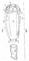
- Fig. 1 is a perspective view of a first embodiment of the assembled invention;
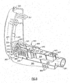
- Fig. 2 is an exploded perspective view of the invention illustrated in Fig. 1 with portions removed to better illustrate the internal structure thereof;
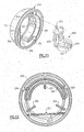
- Figs. 3, 4, 5 and 6 are, respectively, an upper and lower perspective view, top elevation and sectional view of the platform portion of the invention to better illustrate a portion of the structure forming the non-linear orifice;
- Fig. 7 is a perspective view of the rocker and platform portions of the invention as they are installed onto the lower portion of the device housing for producing an oscillatory positive expiratory air pressure;
- Fig. 8 is a perspective view of the assembled device with the upper portion of the device open to better illustrate a portion of the structure for adjusting the magnitude and frequency of the oscillatory positive expiratory air pressure and the ease in which the device may be assembled and disassembled for cleaning;
- Fig. 9 is a top elevation view of the assembled device;
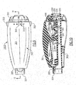
- Fig. 10 is a sectional view of the device as illustrated in Fig. 9 taken along lines 10 - 10 to better illustrate the internal structure for creating the oscillatory positive expiratory air pressure and to control the oscillatory frequency and pressure, and the manner in which the magnitude and frequency of the oscillations can be adjusted;
- Fig. 11 is a rear perspective view of an adjustment dial portion of the invention to better illustrate the manner in which the platform portion illustrated in Figs. 3-6 is positionable relative to the rocker portion illustrated in Fig. 2 to determine the magnitude and frequency of the oscillations;
- Fig. 12 is a planar view of the adjustment dial illustrated in Fig. 1 1 to better illustrate the structure and function thereof;
- Fig. 13 is a mechanical schematic of a second embodiment of the invention utilizing dual rocker and platform assemblies to generate an oscillatory positive expiratory air pressure;
- Fig. 14 is a mechanical schematic of a third embodiment of the invention utilizing the platform and rocker assembly as illustrated herein, but without a magnet control to generate an oscillatory positive expiratory air pressure; and
- Fig. 15 is a mechanical schematic of a fourth embodiment of the invention utilizing a spring-biased air-flow closure to generate an oscillatory positive expiratory air pressure.
-
- Referring now to the drawings, there is illustrated in Figs. 1 and 2 an oscillatory positive expiratory pressure (PEP)
respiratory therapy device 1000 for applying oscillatory positive expiratory air pressure (PEP) therapy to a patient. When expiratory air is passed from a patient through an air-flow tube 200 to an expiratory-air-drivenoscillatory rocker assembly 400 contained within a two-part housing 300, the expiratory-air-drivenoscillatory rocker assembly 400 creates an oscillatory positive expiratory air pressure which is applied to the patient during exhalation. The expiratory-air-drivenoscillatory rocker assembly 400 comprises two portions, arocker portion 440 and a rocker support orplatform portion 480 which act together in creating the oscillatory PEP therapy and are best illustrated in Figs. 2-10. The details of the structure and operation of this oscillatory PEP portion of the device will be described in detail hereinafter. - To control the magnitude and frequency of the oscillatory pressure applied to a patient, a rotatable
frequency control dial 350 is carried by and positioned at the discharge end of an air-flow tube 200. The air-flow tube 200 is carried by alower housing portion 302, and supports therocker assembly 400. By operation of the adjustablefrequency control dial 350 in a manner to be hereinafter described, the relative positioning between the oscillatory PEP inducing portions of theoscillatory rocker assembly 400, therocker portion 440 and therocker support portion 480, is adjusted to control the magnitude and frequency of the oscillatory expiratory air pressure. - The expiratory-air-driven
oscillatory rocker portion 440 is best illustrated in the exploded view of Fig. 2, and Figs. 7, 8 and 10. Therocker support portion 480, which functions in cooperation with therocker portion 440 to produce an oscillatory expiratory air flow and pressure, is also illustrated in the exploded view of Fig. 2, and in more detail in Figs. 3 through 6 and 10. The expiratory-air-drivenoscillatory rocker portion 440 and therocker support portion 480, when assembled together, form therocker assembly 400. - The
rocker assembly 400 is supported on the air-flow tube 200 which comprises a sealed chamber fromapatient input end 201 to adischarge opening 203 which is periodically closed to create the oscillatory PEP treatment. In this manner, therocker assembly 400 functions to create an oscillatory positive expiratory air pressure and flow rate in response to a patient's exhalation, and the patient's expiratory air is thereby directed to and through therocker assembly 400. - As best shown in Figs. 2, 7 and 10, there is illustrated the air-
flow tube 200 having a first orpatient input end 201 for receiving astandard 22mm mouthpiece 202 into which a patient discharges expiratory air. The air passed into the air-flow tube through theinput 201 passes out of the air-flow tube 200 through a discharge opening 203, and is applied to therocker assembly 400. The air-flow tube discharge opening 203 is formed in the top flatplanar surface 205 of the air-flow tube 200 and the expiratory air passed there through is applied to theoscillatory rocker assembly 400 for creating the oscillatory PEP therapy for the patient in a manner to be hereinafter described in detail. - While a second opposite end of the air-flow tube could be closed, for convenience of use, the
opposite end 204 is open and carries a conventional one-way flapper valve 225. Theflapper valve 225 allows a patient to draw inspiratory air into the air-flow tube 200 through theopening 204, but prevents expiratory air from being passed out of the air-flow tube 200 through theopening 204. To this end the one-way flapper valve 225 is positioned on aspider 206 which is inserted into theopening 204 against a shoulder forming a space sufficient for the one-way operation of the valve. Upon inhalation by a user, thevalve 225 opens and allows air to pass into the air-flow tube 200, and upon exhalation, thevalve 225 is held closed against thespider 206 thereby preventing expiratory air from passing out through thevalve 225. If theend 204 were closed, a user would not be able to inhale through thedevice 1000, but that would not effect the operation of the device in providing oscillatory PEP therapy in the manner to be described herein. - After the expiratory air is applied to the
rocker assembly 400, the air thereafter exits from thedevice 1000 through openings in the rotatable adjustingdial 350 carried in thehousing 300. - As best illustrated in Figs. 2, 7, 8 and 10, the
rocker portion 440 is balanced for pivotal movement aboutpivot pins 441 on spacedpivot supports 481 formed on aplatform 485 of therocker support portion 480. Thepivot pins 441 form a transverse pivot axis for therocker portion 440 which lies in a plane above and extends transverse to the longitudinal axis of theplatform 485. Thepivot pins 441 are limited in their axial and vertical movement by a pair oflocking guides 482, carried by theplatform 485, one of which is positioned adjacent each of the pivot supports 481 to maintain thepivot pins 441 in their proper position on the pivot supports 481. In this manner therocker portion 440 is pivotal relative to therocker support portion 480 regardless of the orientation of thedevice 1000, allowing theoscillatory PEP device 1000 to function regardless of its orientation in use. Abalance pad 442 and balancing cylinder 443 are formed at one end of arocker arm 445 to balance the weight of a cone-shaped air-flow closure member 447 and a pin of magnetically attractable material, such as asteel pin 448, both of which are carried at the opposite end of therocker arm 445. Thepin 448 is carried at the distal end of therocker arm 445 by a plurality of grippingfingers 446 which partially encircle thepin 448 for holding the pin in a position to be exposed to the magnetic field of a disc-shaped magnet 488 carried on the air-flow tube 200 in amagnet holder 490. - The cone-shaped air-flow closure member or air-
flow closure cone 447 is sized and positioned on therocker arm 445 to be periodically inserted into a tapered bell-shaped or trumpet-shaped air-discharge outlet 487 formed in theplatform 485 to create the oscillatory PEP when expiratory air is discharged through the opening 203 in the air-flow tube 200. As best illustrated in Figs. 3 - 6, the interior of the air-discharge outlet 487 has a non-linear taper or bell-shaped interior surface to form a non-linear air discharge outlet for creating the oscillatory PEP therapy in response to the pivotal movement of the air-flow closure cone 447 in to and out therefrom. In this manner thedischarge outlet 487 is periodically closed and re-opened allowing the expiratory air discharged there through to be discharged from thehousing 300 through the openings in the adjustingdial 350. - The
oscillatory rocker assembly 400 is secured on the air-flow tube 200 and positioned within thehousing 300 by means of apositioning tang 484 which extends downwardly from theplatform 485 as best illustrated in Figs.2, 4 and 6. A pair ofside walls 486 of theplatform 485, the bottoms of which rest on the planar surface of the air-flow tube 200, are formed with a ridged finger-engaging surface to facilitate the removal and repositioning of therocker support portion 480 relative to the air-flow tube 200 for cleaning thedevice 1000 as necessary.Sidewalls 209 extend vertically outward from theplanar surface 205 of the air-flow tube 200 and are spaced apart a distance sufficient to receive therocker arm 445 there between. In this manner, the rocker arm is protected between thesidewalls 209 when the upper and lower housing portions, 301 and 302, respectively, are separated for cleaning. This positioning protects therocker assembly 400 from being inadvertently improperly grasped by a user when disassembling thedevice 1000 for cleaning, and the user's attention is directed to the ribbed or ridged finger-engaging surface of theside walls 486 which are preferred for grasping when the rocker assembly is to be removed. - The
tang 484 is secured in achannel 284 extending upwardly from the top of theplanar surface 205 of the air-flow tube 200 to securely position theoscillatory rocker assembly 400 onto the air-flow tube 200. In this manner acircular guide 489 engages with acowling 287 of the complementary air-flow tube discharge opening 203 so that the non-linear tapered, bell-shapeddischarge outlet 487 carried by theplatform 485 is aligned in fluid communication with and extends into the discharge opening 203 in the air-flow tube 200. Anothertang 384 extends downwardly from the interior ofupper portion 301 of thehousing 300 and passes through anaperture 444 in therocker arm 445 to press downwardly against theplatform 485 thereby securing theoscillatory rocker assembly 400 in the proper position on the air-flow tube 200 when the upper 301 and lower 302 portions of thehousing 300 arc engaged. - The upper and lower portions of the housing, 301 and 302, respectively, are pivotally connected to facilitate the opening and closing of the housing such as when it is desired to clean the interior thereof. To this end, as best illustrated in Figs. 2 and 8, the
upper housing 301 is formed with a pair oftabs 303 for engaging a pair of complementary pivot pins 306 formed on thelower housing 302 in a position to engage thetabs 303 to form a pivotal connection therewith. A plurality ofpins 307 extend outwardly from theupper housing 301 to engagecomplementary receptacles 308 formed on thelower housing 302 to maintain the two portions of the housing closed unless it is desired that they be opened for access to the interior of thehousing 300. When it is desired to open thehousing 300, the sides of theupper housing portion 301 are compressed towards each other to facilitate releasing thepins 307 from thereceptacles 308. When thepins 307 are so positioned, the twohousing portions pivot connection housing 300 and the components enclosed therein. A securingtab 305 extends outwardly from the end of theupper housing 301 opposite to thetabs 303 to engage a complementary recess formed in thelower housing 302 to facilitate securing the twohousing portions housing 300 together and themouthpiece 202 is passed over thetab 305 when place onto theend 201 of the air-flow tube 200. - To create the periodically interrupted discharge of expiratory air for applying the oscillatory PEP therapy to a patient, the magnetically attractable material or
steel pin 448 is carried on thepivotal rocker arm 445 at a position in operative proximity to themagnet 488 carried by therocker support portion 480. While therocker assembly 400 may be constructed without magnetically attractable material and a magnet/magnet holder, thedevice 1000 will still provide oscillatory PEP therapy. The use of the magnetic material and magnet/magnet holder permits thedevice 1000 to control the magnitude and frequency of the oscillations. - The
magnet 488 is carried in amagnet holder 490 having a receiver portion orpocket 491 formed in a circular configuration for receiving the disc-shapedmagnet 488, and has a plurality of gripping or centeringfingers 492 for retaining themagnet 488 in the circular-shaped receiver pocket. Thereceiver pocket 491 is formed at one end of a verticallypositionable carrier 495, which is guided in its vertical movement by a pair ofguide rails 210 extending outwardly from the flatplanar surface 205 of the air-flow tube 200. The opposite end of thecarrier 495 extends vertically upward from a position adjacent to the circular-shapedreceiver pocket 491 and terminates in afollower tip 496 which engages acam surface 396 formed in the oscillationfrequency control dial 350, as illustrated in Figs. 7, 8 and 11. - In this manner, rotation of the
frequency control dial 350 will move thefollower tip 496 causing thecarrier 495 to move vertically between the guide rails 210. Raising or lowering thecarrier 495 moves themagnet 488 towards or away from thesteel pin 448 to vary the magnetic attractive force there between. Rotation of the frequency control dial 350 controls the frequency of the oscillations by which the PEP treatment or therapy is applied in accordance with the desires of the healthcare provider. While thedevice 1000 will function to provide an oscillatory PEP pulse without the use of the magnetic field between themagnet 488 and thesteel pin 448, because of the opening and closing of the taperednon-linear discharge outlet 487 due to the movement of the tapered cone-shaped air-flow closure 447 induced in response to the patient's discharge of expiratory air, the use of the magnetic field permits thedevice 1000 to provide an adjustable range in the pressure of the patient's expiratory air discharge required to create the oscillatory positive expiratory pressure pulses. - To assist a patient or the healthcare provider in using the
device 1000 once the proper magnetic field has been set, a plurality ofindicia 310 are spaced along thecontrol dial 350 and the top of theupper portion 301 of thehousing 300. Theseindicia 310, in combination with abase reference point 360 on theupper housing 301, are used to ensure that the correct setting is being maintained after the healthcare provider has established the desired level for treatment. To minimize the occurrence of therotatable adjusting dial 350 being unknowingly rotated, as best illustrated in Fig. 2 a series of tooth-like projections 211 are formed on the air-flow tube 200. These projections are engaged by amating tooth 351 formed on athin chord 352 of plastic material from which theadjusting dial 350 is constructed, and which extends across the lower internal portion of the adjusting dial to form a sounding board. In this manner, when therotatable adjusting dial 350 is turned, the tooth-like projections 211 and themating tooth 351 provide resistance to movement and produce a mechanically generated audible sound to signal that a change in position has occurred. A pair ofstops 354 are formed on the interior of the adjustingdial 350, best illustrated in Figs. 11 and 12, which in combination with aside portion 309 of thelower housing 302, limit the rotational movement of thedial 350 relative to thehousing 300. - The
rotatable adjusting dial 350 is rotatably mounted on the end of the air-flow tube 200 adjacent to theend 204 thereof, and is held in contact by a snap fit therewith and guides 355 which provide three point contact between thedial 350 and the end of the air-flow tube. As expiratory air is passed through therocker assembly 400 the air will freely flow from thehousing 300 through the spaces between thehousing 300 and the adjustingdial 350. - Referring now to the embodiments illustrated in Figs. 13 and 14, there are illustrated two additional embodiments of the invention utilizing a
rocker assembly 400 carried on an air-flow tube 200. In the embodiment illustrated in Fig. 13, two cone-shaped air-flow closure members or air-flow closure cones 447 are utilized supported, one at each end, on a rocker arm 445a pivotally mounted at the approximate center thereof for mutually exclusively closing and opening one of a pair of complementary tapered bell-shaped or trumpet-shaped air-discharge outlets 487 formed in the air-flow tube 200 carried within ahousing 300, not shown in this illustration. As shown in this Fig. theend 204 of the air-flow tube is closed, but could be formed with a one-way valve 225 as previously described. In this embodiment it is believed that the flow of air out of one of the air-discharge outlets 487 will cause the complementary air-flow closure cone 447 to be accelerated downwardly increasing the pressure in the air-flow tube such that the other air-flow closure cone 447 will be forced upwardly from its associated air-discharge outlet 487 until the flow of expiratory air through theoutlet 487 and over the combination of the conical surface of the air-flow closure cone 487 and the tapered non-linear orifice of the air-discharge outlet 487 will cause theconc 447 to be accelerated downwardly towards theoutlet 487 repeating the cycle and generating an oscillatory expiratory air pulse to the user as the two discharge outlets are cycled on and off. - The embodiment illustrated in Fig. 14 is similar to the embodiment described herein without the magnetic 488 and
magnet carrier 495. In this embodiment there would be no oscillatory frequency control and, therefore, no need for afrequency adjusting dial 350. The unit would not be operable in all orientations, but would still provide oscillatory PEP therapy at a fixed frequency which would be dependent upon the weight of the rocker assembly components. - In the embodiment illustrated in Fig. 15, the air-
flow tube 200 has anopen end 204 through which expiratory air passes after passing through a modified air-flow closure cone 447 and associated air-discharge outlet 487. The air-flow closure cone 447 is mounted on a spring-loadedshaft 447b which is adjustable to vary the force which is applied to hold the air-flow closure cone 447 against the expiratory air pressure applied through the associated air-discharge outlet 487. When the expiratory air pressure increases above the spring force applied to the air-flow closure cone 447, the expiratory air will be discharged through the associated air-discharge outlet functioning in the manner here to fore described and causing an oscillatory PEP to be applied to the user. - During use of the variable frequency or oscillatory PEP device 1000 a patient's expiratory air is delivered through the
input end 201 of the air-flow tube 200 and passes through the opening 203 to theoscillatory rocker assembly 400. Accordingly, the expiratory air pressure is applied against the cone-shapedclosure 447 of therocker assembly 400 which forms a closure of the non-linear discharge opening ororifice 487. The pressure of the patient's expiratory air will raise the cone-shapedclosure 447, causing therocker portion 440 to pivot about the pivot pins 441 against the force of the magnetic field between themagnet 488 carried on the pivotalrocker support portion 480 and thesteel pin 448 carried on therocker assembly 400. As the cone-shapedclosure 447 moves upwardly in response to the increasing expiratory air pressure, the constant taper of the conical shape in conjunction with the bell-shaped non-linear taper of the non-linear discharge opening ororifice 487 increases the effective discharge area thereby decreasing the air pressure applied against the cone-shapedclosure 447 and reducing the upward acceleration of therocker arm 445. - When the magnetic force and the Coanda effect of the air flow over the bell-shaped or non-linear tapered interior of the
discharge outlet 487 overcome the expiratory air pressure applied to the tapered cone-shapedclosure 447, theclosure 447 will again begin to move downwardly and accelerate into the bell-shaped non-linear-tapereddischarge orifice 487. As the cone descends into the air flow path through the discharge outlet ororifice 487, the annular flow area diminishes reducing the airflow rate and increasing the air pressure. This continues until the downward momentum is overcome and thecone 447 resumes its upward acceleration. Maximum pressure is obtained at this point and another cycle begins. - While this invention has been described in the specification and illustrated in the drawings with reference to preferred embodiments, the structures of which have been disclosed herein, it will be understood by those skilled in the art to which this invention pertains that various changes may be made and equivalents may be substituted for elements of the invention without departing from the scope of the claims. Therefore, it is intended that the invention not be limited to the particular embodiments disclosed in the specification and shown in the drawings as the best modes presently known by the inventors for carrying out this invention nor confined to the details set forth, but that the invention will include all embodiments modifications and changes as may come within the scope of the following claims:
Claims (23)
- An oscillatory positive expiratory pressure therapy device, comprising:an air-flow tube having a path of air flow movement from an inlet opening for receiving expiratory air passed thereto by a user receiving respiratory therapy or care, through an outlet opening for discharging the expiratory air passed through said inlet opening;said air-flow tube including expiratory air responsive closure means positioned in said path of air flow movement and actuable between an open position and a closed position in response to the pressure of expiratory air passed thereto; andsaid expiratory air responsive closure means including a normally closed non-linear discharge outlet which is opened in response to the presence of a predetermined pressure of expiratory air being passed in said path of air flow movement, and which closes in response to a predetermined rate of air pressure decrease through said non-linear discharge opening.
- The oscillatory positive expiratory pressure therapy device of Claim 1 wherein said expiratory air responsive closure means includes a cone-shaped closure member movable in response to expiratory air pressure between a closed position blocking the flow of expiratory air in said path of air flow movement and an open position permitting the flow of expiratory air in said path of air flow movement.
- The oscillatory positive expiratory pressure therapy device of Claim 2 wherein said cone-shaped closure member is carried by a spring-loaded shaft.
- The oscillatory positive expiratory pressure therapy device of Claim 3 wherein said spring-loaded shaft is adjustable to vary the force which is applied to hold said air-flow closure cone against said expiratory air pressure.
- The oscillatory positive expiratory pressure therapy device of Claim 2 wherein said cone-shaped closure member is pivotally movable between said closed position and said open position.
- The oscillatory positive expiratory pressure therapy device of Claim 1 wherein said non-linear discharge outlet positioned in said path of air flow movement comprises a non-linear tapered discharge orifice.
- The oscillatory positive expiratory pressure therapy device of Claim 1 wherein said non-linear discharge outlet positioned in said path of air flow movement comprises a bell-shaped discharge orifice.
- The oscillatory positive expiratory pressure therapy device of Claim 1 wherein said non-linear discharge outlet positioned in said path of air flow movement comprises a trumpet-shaped air discharge outlet.
- The oscillatory positive expiratory pressure therapy device of Claim 1 further including a magnetic force field applying means for generating a biasing force effecting the opening and closing of said non-linear discharge opening.
- The oscillatory positive expiratory pressure therapy device of Claim 9 further including means for adjusting the magnitude of the magnetic force field applying means to bias the opening and closing of said non-linear discharge opening.
- The oscillatory positive expiratory pressure therapy device of Claim 1 wherein said expiratory air responsive closure means positioned in said path of air flow movement and actuable between an open position and a closed position in response to the pressure of expiratory air passed thereto comprises an oscillatory rocker assembly including a rocker portion pivotally supported on a rocker support portion.
- The oscillatory positive expiratory pressure therapy device of Claim 11 wherein said rocker portion includes a cone-shaped closure member carried on said rocker portion for pivotal movement into and out from said non-linear discharge opening; and
said rocker support portion includes a bell-shaped non- linear discharge ori fice which is opened and closed in response to the movement of said cone-shaped closure member. - The oscillatory positive expiratory pressure therapy device of Claim 10 wherein said means for adjusting the magnitude of the magnetic force field applying means includes a rotatable frequency control dial.
- The oscillatory positive expiratory pressure therapy device of Claim 13 wherein said rotatable frequency control dial includes a receiving aperture operatively connected to said expiratory air responsive closure means for adjusting the expiratory air pressure for opening said non-linear discharge opening.
- An oscillatory positive expiratory pressure therapy device, comprising:an air-flow tube having a path of air flow movement from an inlet opening for receiving expiratory air passed thereto by a user receiving respiratory therapy or care, through an outlet opening for discharging the expiratory air passed through said inlet opening;said air-flow tube including expiratory air responsive closure means positioned in said path of air flow movement and actuable between an open position and a closed position in response to the pressure of expiratory air passed thereto;said expiratory air responsive closure means including a normally closed discharge outlet which is opened in response to the presence of a predetermined pressure of expiratory air being passed in said path of air flow movement, and which closes in response to a predetermined rate of air pressure decrease through said discharge opening; andsaid expiratory air responsive closure means including a closure member pivotally movable in response to expiratory air pressure between a closed position blocking the flow of expiratory air in said path of air flow movement and an open position permitting the flow of expiratory air in said path of air flow movement.
- The oscillatory positive expiratory pressure therapy device of Claim 15 wherein said expiratory air responsive closure means positioned in said path of air flow movement and actuable between an open position and a closed position in response to the pressure of expiratory air passed thereto comprises an oscillatory rocker assembly.
- The oscillatory positive expiratory pressure therapy device of Claim 16 wherein said oscillatory rocker assembly includes a cone-shaped member and a complementary curvi linear discharge orifice which is opened and closed in response to the movement of said cone-shaped closure member.
- A method of selectively effecting oscillatory positive expiratory pressure therapy in a patient, comprising:passing a flow of patient-induced expiratory air into an air-flow tube for passing the expiratory air in a path of air flow movement from an inlet opening for receiving expiratory air passed thereto by a user receiving respiratory therapy or care, through an outlet opening for discharging the expiratory air passed through said inlet opening;blocking a discharge opening for expiratory air moving in said path of air flow movement and thereby increasing the expiratory air pressure as said expiratory air continues in said path of air movement; andopening said discharge opening in response to the increase of the expiratory air pressure to a predetermined level, and then reducing the expiratory air pressure at a variable rate by passing the discharge of expiratory air through a non-linear discharge orifice inducing an oscillatory positive expiratory pressure in the patient.
- The method of selectively effecting oscillatory positive expiratory pressure therapy of Claim 18 wherein the steps of blocking the discharge opening for expiratory air moving in said path of air flow movement and thereby increasing the expiratory air pressure as said expiratory air continues to flow in said path of air flow movement, and opening said discharge opening in response to the increase of the expiratory air pressure to a predetermined level and then reducing the expiratory air pressure at a variable rate bypassing the discharge of expiratory air through a non-linear discharge orifice to induce an oscillatory positive expiratory pressure in the patient are repeated until a sufficient oscillatory positive expiratory pressure therapy has been effected.
- The method of selectively effecting oscillatory positive expiratory pressure therapy of Claim 18 further including applying a biasing force for closing said discharge opening to control the predetermined level of expiratory air pressure.
- The method of selectively effecting oscillatory positive expiratory pressure therapy of Claim 20 wherein said biasing force is a magnetic force field.
- The method of selectively effecting oscillatory positive expiratory pressure therapy of Claim 18 wherein said step of reducing the expiratory air pressure at a variable rate by passing the discharge of expiratory air through a non-linear discharge orifice includes application of the Coanda effect.
- An oscillatory positive expiratory pressure therapy device, comprising:an air-flow tube having a path of air flow movement from an inlet opening for receiving expiratory air passed thereto by a user receiving respiratory therapy or care, through an outlet opening for discharging the expiratory air passed through said inlet opening;said air-flow tube including at least two expiratory air responsive closure means positioned in said path of air flow movement and actuable between an open position and a closed position in response to the pressure of expiratory air passed thereto; andeach one of said expiratory air responsive closure means including a normally closed non-linear discharge outlet which is opened in response to the presence of a predetermined pressure of expiratory air being passed in said path of air flow movement, and which closes in response to a predetermined rate of air pressure decrease through said non-linear discharge opening.
Applications Claiming Priority (2)
| Application Number | Priority Date | Filing Date | Title |
|---|---|---|---|
| US396218 | 1995-02-27 | ||
| US10/396,218 US7059324B2 (en) | 1999-11-24 | 2003-03-24 | Positive expiratory pressure device with bypass |
Publications (2)
| Publication Number | Publication Date |
|---|---|
| EP1464357A1 true EP1464357A1 (en) | 2004-10-06 |
| EP1464357B1 EP1464357B1 (en) | 2010-01-06 |
Family
ID=32850533
Family Applications (1)
| Application Number | Title | Priority Date | Filing Date |
|---|---|---|---|
| EP04251657A Expired - Lifetime EP1464357B1 (en) | 2003-03-24 | 2004-03-23 | Positive expiratory pressure device |
Country Status (7)
| Country | Link |
|---|---|
| US (2) | US7059324B2 (en) |
| EP (1) | EP1464357B1 (en) |
| JP (1) | JP4489478B2 (en) |
| AT (1) | ATE454179T1 (en) |
| AU (1) | AU2004200770B8 (en) |
| DE (1) | DE602004024938D1 (en) |
| ES (1) | ES2338113T3 (en) |
Cited By (27)
| Publication number | Priority date | Publication date | Assignee | Title |
|---|---|---|---|---|
| EP1897576A1 (en) * | 2006-09-05 | 2008-03-12 | South Bank University Enterprises Limited | Portable breathing device |
| EP1908489A1 (en) | 2006-10-03 | 2008-04-09 | Smiths Medical ASD, Inc. | Vibratory pep therapy system with medicated aerosol nebulizer |
| EP1897597A3 (en) * | 2006-09-05 | 2009-06-17 | Roger Leslie Brown | Randomly interrupted breathing device |
| WO2012038864A3 (en) * | 2010-09-21 | 2012-06-21 | Koninklijke Philips Electronics N.V. | Vibratory positive expiratory pressure device |
| US8327849B2 (en) | 2008-10-28 | 2012-12-11 | Trudell Medical International | Oscillating positive expiratory pressure device |
| US8485179B1 (en) | 2009-02-23 | 2013-07-16 | Trudell Medical International | Oscillating positive expiratory pressure device |
| US8539951B1 (en) | 2008-05-27 | 2013-09-24 | Trudell Medical International | Oscillating positive respiratory pressure device |
| WO2014140532A1 (en) * | 2013-03-15 | 2014-09-18 | Sheffield Hallam University | Positive expiratory pressure device with electronic monitoring |
| USD731050S1 (en) | 2011-06-06 | 2015-06-02 | Trudell Medical International | Oscillating positive expiratory pressure device |
| US9149589B2 (en) | 2009-02-23 | 2015-10-06 | Trudell Medical International | Method and device for performing orientation dependent oscillating positive expiratory pressure therapy |
| US9517315B2 (en) | 2012-11-30 | 2016-12-13 | Trudell Medical International | Oscillating positive expiratory pressure device |
| USD778429S1 (en) | 2015-09-02 | 2017-02-07 | Trudell Medical International | Respiratory treatment device |
| USD780906S1 (en) | 2015-09-02 | 2017-03-07 | Trudell Medical International | Respiratory treatment device |
| US9849257B2 (en) | 2013-08-22 | 2017-12-26 | Trudell Medical International | Oscillating positive respiratory pressure device |
| US9950129B2 (en) | 2014-10-27 | 2018-04-24 | Covidien Lp | Ventilation triggering using change-point detection |
| US10004872B1 (en) | 2015-03-06 | 2018-06-26 | D R Burton Healthcare, Llc | Positive expiratory pressure device having an oscillating valve |
| CN108465145A (en) * | 2011-09-26 | 2018-08-31 | 瑞思迈巴黎股份有限公司 | Ventilator apparatus and application |
| US10272224B2 (en) | 2013-07-12 | 2019-04-30 | Trudell Medical International | Huff cough simulation device |
| US10363383B2 (en) | 2014-02-07 | 2019-07-30 | Trudell Medical International | Pressure indicator for an oscillating positive expiratory pressure device |
| US10362967B2 (en) | 2012-07-09 | 2019-07-30 | Covidien Lp | Systems and methods for missed breath detection and indication |
| US10449324B2 (en) | 2015-07-30 | 2019-10-22 | Trudell Medical International | Combined respiratory muscle training and oscillating positive expiratory pressure device |
| US10582880B2 (en) | 2006-04-21 | 2020-03-10 | Covidien Lp | Work of breathing display for a ventilation system |
| US10857317B2 (en) | 2015-12-04 | 2020-12-08 | Trudell Medical International | Huff cough simulation device |
| US10953278B2 (en) | 2018-02-02 | 2021-03-23 | Trudell Medical International | Oscillating positive expiratory pressure device |
| US11559723B2 (en) | 2017-05-03 | 2023-01-24 | Trudell Medical International | Combined oscillating positive expiratory pressure therapy and Huff Cough simulation device |
| US11672934B2 (en) | 2020-05-12 | 2023-06-13 | Covidien Lp | Remote ventilator adjustment |
| US11951252B2 (en) | 2020-01-28 | 2024-04-09 | Trudell Medical International | Oscillating positive expiratory pressure device |
Families Citing this family (60)
| Publication number | Priority date | Publication date | Assignee | Title |
|---|---|---|---|---|
| US6024089A (en) | 1997-03-14 | 2000-02-15 | Nelcor Puritan Bennett Incorporated | System and method for setting and displaying ventilator alarms |
| US7059324B2 (en) * | 1999-11-24 | 2006-06-13 | Smiths Medical Asd, Inc. | Positive expiratory pressure device with bypass |
| US8333728B2 (en) * | 2005-12-01 | 2012-12-18 | Medtronic, Inc. | Implantable cerebrospinal fluid flow device and method of controlling flow of cerebrospinal fluid |
| US7909033B2 (en) | 2006-05-03 | 2011-03-22 | Comedica Incorporated | Breathing treatment apparatus |
| US8051854B2 (en) | 2006-09-15 | 2011-11-08 | Comedica Incorporated | Continuous high-frequency oscillation breathing treatment apparatus |
| US7784461B2 (en) | 2006-09-26 | 2010-08-31 | Nellcor Puritan Bennett Llc | Three-dimensional waveform display for a breathing assistance system |
| US7779841B2 (en) | 2006-11-13 | 2010-08-24 | Carefusion 2200, Inc. | Respiratory therapy device and method |
| US8528547B2 (en) * | 2007-04-02 | 2013-09-10 | Carefusion 2200, Inc. | High frequency oscillation respiratory therapy |
| US9050434B2 (en) | 2007-05-18 | 2015-06-09 | Comedica Incorporated | Lung therapy device |
| US8251876B2 (en) | 2008-04-22 | 2012-08-28 | Hill-Rom Services, Inc. | Breathing exercise apparatus |
| US20100180899A1 (en) * | 2009-01-21 | 2010-07-22 | Michael Capezzuto | Air flow regulating device |
| US9151425B2 (en) * | 2009-11-02 | 2015-10-06 | Comedica Incorporated | Multiple conduit connector apparatus and method |
| US20110100360A1 (en) * | 2009-11-02 | 2011-05-05 | Joseph Dee Faram | Composite lung therapy device and method |
| US9119925B2 (en) | 2009-12-04 | 2015-09-01 | Covidien Lp | Quick initiation of respiratory support via a ventilator user interface |
| US8335992B2 (en) | 2009-12-04 | 2012-12-18 | Nellcor Puritan Bennett Llc | Visual indication of settings changes on a ventilator graphical user interface |
| US8924878B2 (en) | 2009-12-04 | 2014-12-30 | Covidien Lp | Display and access to settings on a ventilator graphical user interface |
| US9262588B2 (en) | 2009-12-18 | 2016-02-16 | Covidien Lp | Display of respiratory data graphs on a ventilator graphical user interface |
| US8499252B2 (en) | 2009-12-18 | 2013-07-30 | Covidien Lp | Display of respiratory data graphs on a ventilator graphical user interface |
| EP2444114B1 (en) * | 2010-10-20 | 2016-09-28 | Hill-Rom Services Pte. Ltd. | Apparatus for positive expiratory pressure therapy |
| US9084859B2 (en) | 2011-03-14 | 2015-07-21 | Sleepnea Llc | Energy-harvesting respiratory method and device |
| US11452838B2 (en) | 2011-04-28 | 2022-09-27 | Michael J. Rusher | Positive expiratory pressure devices with flutter valve |
| US9180271B2 (en) | 2012-03-05 | 2015-11-10 | Hill-Rom Services Pte. Ltd. | Respiratory therapy device having standard and oscillatory PEP with nebulizer |
| US9795752B2 (en) | 2012-12-03 | 2017-10-24 | Mhs Care-Innovation, Llc | Combination respiratory therapy device, system, and method |
| ITLE20130005A1 (en) * | 2013-03-05 | 2014-09-06 | Cesare Aversa | DEVICE FOR RESPIRATORY GYMNASTICS |
| USD753284S1 (en) * | 2013-06-12 | 2016-04-05 | M. LaQuisha Burks | Expiratory muscle strength trainer adapter |
| GB201310824D0 (en) | 2013-06-18 | 2013-07-31 | Smiths Medical Int Ltd | Respiratory therapy apparatus and methods |
| GB201310826D0 (en) | 2013-06-18 | 2013-07-31 | Smiths Medical Int Ltd | Respiratory therapy apparatus and methods |
| GB201316223D0 (en) | 2013-09-12 | 2013-10-30 | Smiths Medical Int Ltd | Respiratory therapy apparatus and methods |
| GB201400188D0 (en) * | 2014-01-07 | 2014-02-26 | Smiths Medical Int Ltd | Respiratory therapy apparatus |
| GB201404265D0 (en) | 2014-03-11 | 2014-04-23 | Smiths Medical Int Ltd | Respiratory analysis and treatment |
| GB201407571D0 (en) | 2014-04-30 | 2014-06-11 | Smiths Medical Int Ltd | Respiratory therapy devices |
| US10434277B2 (en) | 2014-08-14 | 2019-10-08 | Rbt Medical Products Llc | Positive expiratory pressure device and methods of using same |
| GB201420127D0 (en) * | 2014-11-12 | 2014-12-24 | Smiths Medical Int Ltd | Respiratory therapy apparatus |
| GB201420518D0 (en) | 2014-11-19 | 2014-12-31 | Smiths Medical Int Ltd | Respiratory therapy apparatus |
| EP3229883A1 (en) | 2014-12-11 | 2017-10-18 | Smiths Medical International Limited | Respiratory therapy apparatus |
| CN107735135B (en) | 2015-04-02 | 2020-06-26 | 希尔-罗姆服务私人有限公司 | Manifold for a respiratory device |
| USD779071S1 (en) | 2015-08-14 | 2017-02-14 | Christopher D. Warner, III | Positive expiratory pressure device |
| FR3046937B1 (en) * | 2016-01-25 | 2019-08-09 | Universite Grenoble Alpes | ALTITUDE ACCLIMATING DEVICE AND METHOD OF OPERATING THE SAME. |
| WO2017178776A1 (en) | 2016-04-14 | 2017-10-19 | Smiths Medical International Limited | Respiratory therapy devices |
| WO2017187116A1 (en) | 2016-04-27 | 2017-11-02 | Smiths Medical International Limited | Respiratory therapy apparatus |
| GB201608128D0 (en) | 2016-05-07 | 2016-06-22 | Smiths Medical Int Ltd | Respiratory monitoring apparatus |
| WO2018007997A1 (en) | 2016-07-08 | 2018-01-11 | Trudell Medical International | Smart oscillating positive expiratory pressure device |
| AU2017295022B2 (en) * | 2016-07-13 | 2021-11-18 | Aerofit.Dk Aps | Respiratory device and system for exercising and analysing respiration of a subject |
| GB201706505D0 (en) | 2017-04-25 | 2017-06-07 | 3M Innovative Properties Co | Medicinal inhaler drive mechanism |
| USD874006S1 (en) | 2017-06-15 | 2020-01-28 | Aerofit.Dk Aps | Respiratory exercise device |
| KR102168758B1 (en) * | 2018-01-16 | 2020-10-22 | 연세대학교 원주산학협력단 | Portable respiration training device system and thereof methods with training function to strengthen respiratory muscles |
| USD926308S1 (en) * | 2018-05-30 | 2021-07-27 | Medipines Corporation | Breathing tube for a respiratory gas exchange monitor |
| ES2955038T3 (en) | 2018-06-04 | 2023-11-28 | Trudell Medical Int | Positive air pressure therapy device |
| GB201809559D0 (en) * | 2018-06-09 | 2018-07-25 | Smiths Medical International Ltd | Respiratory therapy apparatus and methods |
| GB201810197D0 (en) | 2018-06-21 | 2018-08-08 | Smiths Medical International Ltd | Respiratory therapy devices and assemblies |
| GB201904825D0 (en) | 2019-04-05 | 2019-05-22 | Smiths Medical International Ltd | Respiratory therapy apparatus |
| EP4186552A1 (en) | 2019-04-17 | 2023-05-31 | ResMed Pty Ltd | Cpap system with resilient sealing for heater plate |
| EP4021542A4 (en) | 2019-08-27 | 2023-09-06 | Trudell Medical International | Smart oscillating positive expiratory pressure device |
| GB202010540D0 (en) | 2020-07-09 | 2020-08-26 | Smiths Medical International Ltd | Respiratory therapy device |
| TWI779663B (en) * | 2021-06-15 | 2022-10-01 | 岩成科技事業股份有限公司 | Oscillating positive expiratory pressure device |
| GB202109719D0 (en) | 2021-07-06 | 2021-08-18 | Smiths Medical International Ltd | Respiratory therapy devices |
| GB202110225D0 (en) | 2021-07-15 | 2021-09-01 | Smiths Medical International Ltd | Respiratory therapy devices |
| CN113599643B (en) * | 2021-08-05 | 2024-01-02 | 宁波蓝柏医疗器械有限公司 | Breathe double-purpose vibration sputum excretion ware |
| CN113648619A (en) * | 2021-09-26 | 2021-11-16 | 重庆上品益生电子商务有限公司 | Breathing training device |
| CN114082161B (en) * | 2021-12-10 | 2022-07-22 | 上海市肺科医院 | Respiratory function training device after lung transplantation |
Citations (4)
| Publication number | Priority date | Publication date | Assignee | Title |
|---|---|---|---|---|
| RU2026057C1 (en) * | 1991-02-15 | 1995-01-09 | Николай Васильевич Зародин | Device for curing diseases of respiratory system |
| US5451190A (en) * | 1992-04-10 | 1995-09-19 | Varioraw Percutive S.A. | Apparatus for respiratory therapy |
| EP1103287A2 (en) | 1999-11-24 | 2001-05-30 | DHD Healthcare Corporation | Positive expiratory pressure device |
| US20030127092A1 (en) * | 1999-11-24 | 2003-07-10 | Dhd Healthcare Corporation | Positive expiratory pressure device with bypass |
Family Cites Families (56)
| Publication number | Priority date | Publication date | Assignee | Title |
|---|---|---|---|---|
| US651731A (en) * | 1898-09-24 | 1900-06-12 | Taylor Mfg | Turbine water-wheel. |
| US2918917A (en) | 1955-03-02 | 1959-12-29 | John H Emerson | Apparatus for vibrating portions of a patient's airway |
| US3753436A (en) * | 1970-04-06 | 1973-08-21 | H Pohndorf | Automatic respirator |
| US3643686A (en) * | 1970-10-21 | 1972-02-22 | Ewald Koegel | High-velocity breathing valve |
| US3710780A (en) | 1971-08-05 | 1973-01-16 | R Milch | Respiratory device with variable expiratory pressure resistance |
| GB1471916A (en) * | 1974-03-14 | 1977-04-27 | Plessey Co Ltd | Fuel injection arrangements having vibrating fuel injection nozzles |
| GB1455583A (en) * | 1973-02-07 | 1976-11-17 | Univ Newcastle | Lung ventilators |
| US3908987A (en) * | 1973-09-27 | 1975-09-30 | John R Boehringer | Controlled positive end pressure expiratory device |
| US3867985A (en) * | 1974-01-11 | 1975-02-25 | Thelton E Wilkinson | Apparatus for and method of preventing blow-out while removing a fish within wash pipe from a borehole |
| US4231375A (en) * | 1977-10-20 | 1980-11-04 | Boehringer John R | Pulmonary exerciser |
| USRE32553E (en) * | 1978-11-29 | 1987-12-08 | Exhalation valve assembly | |
| US4221381A (en) | 1978-12-26 | 1980-09-09 | Albany International Corp. | Respiratory exerciser |
| US4245633A (en) * | 1979-01-31 | 1981-01-20 | Erceg Graham W | PEEP providing circuit for anesthesia systems |
| US4327740A (en) | 1979-11-19 | 1982-05-04 | Clyde Shuman | Incentive spirometer |
| US4454893A (en) * | 1981-11-30 | 1984-06-19 | Puritan-Bennett Corp. | Low-noise diaphragm for use in exhalation valve |
| US4601465A (en) | 1984-03-22 | 1986-07-22 | Roy Jean Yves | Device for stimulating the human respiratory system |
| US4552142A (en) * | 1984-05-10 | 1985-11-12 | Ohio Medical Research, Inc. | Ventilator system having a control valve in the ventilator circuit |
| US4611591A (en) | 1984-07-10 | 1986-09-16 | Sharp Kabushiki Kaisha | Expiration valve control for automatic respirator |
| US4651731A (en) | 1984-09-17 | 1987-03-24 | Figgie International Inc. | Self-contained portable single patient ventilator/resuscitator |
| US4739987A (en) | 1985-10-28 | 1988-04-26 | Nicholson Marguerite K | Respiratory exerciser |
| US4828648A (en) * | 1986-05-29 | 1989-05-09 | Rockwell International Corporation | Liquid phase epitaxy apparatus and method |
| US5067487A (en) * | 1986-07-07 | 1991-11-26 | Jack Bauman | Resuscitator |
| DE3773396D1 (en) | 1987-10-22 | 1991-10-31 | Varioraw Percutive Sa | RESISTANCE DEVICE AGAINST BREATHING TO IMPROVE LUNG VENTILATION. |
| DK168888A (en) | 1988-03-25 | 1989-09-26 | Ambu Int As | RESPIRATION TRAINING DEVICE |
| DE3822949A1 (en) | 1988-07-07 | 1990-01-11 | Draegerwerk Ag | PNEUMATIC CONTROL VALVE |
| US5020532A (en) * | 1988-11-14 | 1991-06-04 | Baxter International Inc. | Exhalation valve for respiratory circuit |
| EP0372148A1 (en) | 1988-12-09 | 1990-06-13 | Erik Folke Norell | Lung exercising device |
| BE1004384A3 (en) | 1989-08-03 | 1992-11-10 | Labaere Emmanuel | Device for applying on and techniques exhalation. |
| US5027809A (en) | 1990-05-17 | 1991-07-02 | Robinson Pat D | "Peeper" performance hand held nebuilizer attachment with adjustability of expiratory pressures and expiratory restriction |
| US5109840A (en) * | 1991-02-14 | 1992-05-05 | Specialty Packaging Licensing Company | Resuscitator having directional control valve with internal "PEEP" adjustment valve |
| US5277195A (en) * | 1992-02-03 | 1994-01-11 | Dura Pharmaceuticals, Inc. | Portable spirometer |
| DE4218926A1 (en) * | 1992-06-10 | 1993-12-16 | Asea Brown Boveri | Device for measuring a gas density |
| US5301667A (en) * | 1992-08-03 | 1994-04-12 | Vital Signs, Inc. | Pressure limiting valve for ventilation breathing bag apparatus |
| TW258695B (en) * | 1993-02-16 | 1995-10-01 | Sakura Color Prod Corp | |
| US5439430A (en) | 1993-05-10 | 1995-08-08 | Rubens; Louis C. | Respiratory exerciser |
| US5357951A (en) * | 1993-06-02 | 1994-10-25 | Mercury Enterprises, Inc | Cardiac pulmonary resuscitator apparatus valve with integral air sampling port |
| US5598839A (en) * | 1994-04-20 | 1997-02-04 | Diemolding Corporation | Positive expiratory pressure device |
| US5540220A (en) | 1994-12-08 | 1996-07-30 | Bear Medical Systems, Inc. | Pressure-limited, time-cycled pulmonary ventilation with volume-cycle override |
| US5658221A (en) | 1995-02-10 | 1997-08-19 | Hougen; Everett D. | Portable personal breathing apparatus and method of using same |
| JP3786961B2 (en) | 1995-02-10 | 2006-06-21 | エヴァレット ディー ホーゲン | Portable personal breathing device |
| US6083141A (en) | 1995-02-10 | 2000-07-04 | Hougen; Everett D. | Portable respiratory exercise apparatus and method for using the same |
| US5632298A (en) | 1995-03-17 | 1997-05-27 | Artinian; Hagop | Resuscitation and inhalation device |
| US5899832A (en) | 1996-06-14 | 1999-05-04 | Hougen; Everett D. | Compact lung exercising device |
| US5791339A (en) | 1997-03-13 | 1998-08-11 | Nellcor Puritan Bennettt Incorprated | Spring piloted safety valve with jet venturi bias |
| US6058932A (en) | 1997-04-21 | 2000-05-09 | Hughes; Arthur R. | Acoustic transceiver respiratory therapy apparatus |
| SE9703290D0 (en) * | 1997-09-11 | 1997-09-11 | Siemens Elema Ab | ventilator |
| US6102038A (en) | 1998-05-15 | 2000-08-15 | Pulmonetic Systems, Inc. | Exhalation valve for mechanical ventilator |
| WO2000027455A1 (en) * | 1998-11-06 | 2000-05-18 | Salter Labs | Nebulizer mouthpiece and accessories |
| US6283122B1 (en) * | 1999-03-10 | 2001-09-04 | Flight Medical Ltd. | Exhalation valve for respirator |
| AU778777B2 (en) * | 1999-09-23 | 2004-12-23 | Fisher & Paykel Healthcare Limited | Breathing assistance apparatus |
| US6210345B1 (en) * | 1999-10-04 | 2001-04-03 | American Biosystems, Inc. | Outcome measuring airway resistance diagnostic system |
| US7059324B2 (en) * | 1999-11-24 | 2006-06-13 | Smiths Medical Asd, Inc. | Positive expiratory pressure device with bypass |
| IL145461A (en) * | 2001-09-16 | 2006-09-05 | Alyn Woldenberg Family Hospita | Inexsufflator |
| US6886561B2 (en) * | 2002-10-09 | 2005-05-03 | Harry Bayron | Respiratory valve |
| GB0317801D0 (en) * | 2003-07-30 | 2003-09-03 | Intersurgical Ltd | Improvements relating to exhalation valves |
| US6997181B2 (en) * | 2004-04-29 | 2006-02-14 | The Lighthouse For The Blind, Inc. | Personal hydration device |
-
2003
- 2003-03-24 US US10/396,218 patent/US7059324B2/en not_active Expired - Lifetime
-
2004
- 2004-02-26 AU AU2004200770A patent/AU2004200770B8/en not_active Expired
- 2004-03-23 AT AT04251657T patent/ATE454179T1/en not_active IP Right Cessation
- 2004-03-23 ES ES04251657T patent/ES2338113T3/en not_active Expired - Lifetime
- 2004-03-23 EP EP04251657A patent/EP1464357B1/en not_active Expired - Lifetime
- 2004-03-23 DE DE602004024938T patent/DE602004024938D1/en not_active Expired - Lifetime
- 2004-03-24 JP JP2004088008A patent/JP4489478B2/en not_active Expired - Lifetime
-
2005
- 2005-12-19 US US11/311,733 patent/US7699054B2/en not_active Expired - Fee Related
Patent Citations (4)
| Publication number | Priority date | Publication date | Assignee | Title |
|---|---|---|---|---|
| RU2026057C1 (en) * | 1991-02-15 | 1995-01-09 | Николай Васильевич Зародин | Device for curing diseases of respiratory system |
| US5451190A (en) * | 1992-04-10 | 1995-09-19 | Varioraw Percutive S.A. | Apparatus for respiratory therapy |
| EP1103287A2 (en) | 1999-11-24 | 2001-05-30 | DHD Healthcare Corporation | Positive expiratory pressure device |
| US20030127092A1 (en) * | 1999-11-24 | 2003-07-10 | Dhd Healthcare Corporation | Positive expiratory pressure device with bypass |
Cited By (63)
| Publication number | Priority date | Publication date | Assignee | Title |
|---|---|---|---|---|
| US10582880B2 (en) | 2006-04-21 | 2020-03-10 | Covidien Lp | Work of breathing display for a ventilation system |
| EP2455137A3 (en) * | 2006-09-05 | 2013-04-24 | Actegy Limited | Randomly operated breathing device |
| EP1897576A1 (en) * | 2006-09-05 | 2008-03-12 | South Bank University Enterprises Limited | Portable breathing device |
| EP1897597A3 (en) * | 2006-09-05 | 2009-06-17 | Roger Leslie Brown | Randomly interrupted breathing device |
| EP2455137A2 (en) * | 2006-09-05 | 2012-05-23 | High Tech Health Limited | Randomly operated breathing device |
| US9205217B2 (en) | 2006-10-03 | 2015-12-08 | Smiths Medical Asd, Inc. | Vibratory PEP therapy system with medicated aerosol nebulizer |
| EP1908489A1 (en) | 2006-10-03 | 2008-04-09 | Smiths Medical ASD, Inc. | Vibratory pep therapy system with medicated aerosol nebulizer |
| US8225785B2 (en) | 2006-10-03 | 2012-07-24 | Smiths Medical Asd, Inc. | Vibratory PEP therapy system with medicated aerosol nebulizer |
| US9636473B2 (en) | 2008-05-27 | 2017-05-02 | Trudell Medical International | Oscillating positive respiratory pressure device |
| US10668235B2 (en) | 2008-05-27 | 2020-06-02 | Trudell Medical International | Oscillating positive respiratory pressure device |
| US9808588B1 (en) | 2008-05-27 | 2017-11-07 | Trudell Medical International | Oscillating positive respiratory pressure device |
| US8539951B1 (en) | 2008-05-27 | 2013-09-24 | Trudell Medical International | Oscillating positive respiratory pressure device |
| US8327849B2 (en) | 2008-10-28 | 2012-12-11 | Trudell Medical International | Oscillating positive expiratory pressure device |
| US8985111B2 (en) | 2008-10-28 | 2015-03-24 | Trudell Medical International | Oscillating positive expiratory pressure device |
| US9913955B2 (en) | 2008-10-28 | 2018-03-13 | Trudell Medical International | Oscillating positive expiratory pressure device |
| US11865254B2 (en) | 2008-10-28 | 2024-01-09 | Trudell Medical International | Oscillating positive expiratory pressure device |
| US9737677B2 (en) | 2008-10-28 | 2017-08-22 | Trudell Medical International | Oscillating positive expiratory pressure device |
| US10668238B2 (en) | 2008-10-28 | 2020-06-02 | Trudell Medical International | Oscillating positive expiratory pressure device |
| US11547819B2 (en) | 2009-02-23 | 2023-01-10 | Trudell Medical International | Device for performing orientation dependent aerosol therapy |
| US9149589B2 (en) | 2009-02-23 | 2015-10-06 | Trudell Medical International | Method and device for performing orientation dependent oscillating positive expiratory pressure therapy |
| US11529480B2 (en) | 2009-02-23 | 2022-12-20 | Trudell Medical International | Oscillating positive expiratory pressure device |
| US8485179B1 (en) | 2009-02-23 | 2013-07-16 | Trudell Medical International | Oscillating positive expiratory pressure device |
| US9220855B2 (en) | 2009-02-23 | 2015-12-29 | Trudell Medical International | Oscillating positive expiratory pressure device |
| US10722668B2 (en) | 2009-02-23 | 2020-07-28 | Trudell Medical International | Oscillating positive expiratory pressure device |
| US10729863B2 (en) | 2009-02-23 | 2020-08-04 | Trudell Medical International | Method and device for performing orientation dependent oscillating positive expiratory pressure therapy |
| US9950128B2 (en) | 2009-02-23 | 2018-04-24 | Trudell Medical International | Oscillating positive expiratory pressure device |
| WO2012038864A3 (en) * | 2010-09-21 | 2012-06-21 | Koninklijke Philips Electronics N.V. | Vibratory positive expiratory pressure device |
| US10039691B2 (en) | 2010-09-21 | 2018-08-07 | Koninklijke Philips N.V. | Vibratory positive expiratory pressure device |
| US9358417B2 (en) | 2011-06-06 | 2016-06-07 | Trudell Medical International | Oscillating positive expiratory pressure device |
| US9981106B2 (en) | 2011-06-06 | 2018-05-29 | Trudell Medical International | Oscillating positive expiratory pressure device |
| US11040167B2 (en) | 2011-06-06 | 2021-06-22 | Trudell Medical International | Oscillating positive expiratory pressure device |
| USD776804S1 (en) | 2011-06-06 | 2017-01-17 | Trudell Medical International | Oscillating positive expiratory pressure device |
| US11738167B2 (en) | 2011-06-06 | 2023-08-29 | Trudell Medical International | Oscillating positive expiratory pressure device |
| US10413698B2 (en) | 2011-06-06 | 2019-09-17 | Trudell Medical International | Oscillating positive expiratory pressure device |
| USD731050S1 (en) | 2011-06-06 | 2015-06-02 | Trudell Medical International | Oscillating positive expiratory pressure device |
| CN108465145A (en) * | 2011-09-26 | 2018-08-31 | 瑞思迈巴黎股份有限公司 | Ventilator apparatus and application |
| US11642042B2 (en) | 2012-07-09 | 2023-05-09 | Covidien Lp | Systems and methods for missed breath detection and indication |
| US10362967B2 (en) | 2012-07-09 | 2019-07-30 | Covidien Lp | Systems and methods for missed breath detection and indication |
| US9517315B2 (en) | 2012-11-30 | 2016-12-13 | Trudell Medical International | Oscillating positive expiratory pressure device |
| US10589043B2 (en) | 2012-11-30 | 2020-03-17 | Trudell Medical International | Oscillating positive expiratory pressure device |
| US10076616B2 (en) | 2012-11-30 | 2018-09-18 | Trudell Medical International | Oscillating positive expiratory pressure device |
| WO2014140532A1 (en) * | 2013-03-15 | 2014-09-18 | Sheffield Hallam University | Positive expiratory pressure device with electronic monitoring |
| US10272224B2 (en) | 2013-07-12 | 2019-04-30 | Trudell Medical International | Huff cough simulation device |
| US10814080B2 (en) | 2013-08-22 | 2020-10-27 | Trudell Medical International | Oscillating positive respiratory pressure device |
| US9849257B2 (en) | 2013-08-22 | 2017-12-26 | Trudell Medical International | Oscillating positive respiratory pressure device |
| US11813398B2 (en) | 2014-02-07 | 2023-11-14 | Trudell Medical International | Pressure indicator for an oscillating positive expiratory pressure device |
| US10363383B2 (en) | 2014-02-07 | 2019-07-30 | Trudell Medical International | Pressure indicator for an oscillating positive expiratory pressure device |
| US11116923B2 (en) | 2014-02-07 | 2021-09-14 | Trudell Medical International | Pressure indicator for an oscillating positive expiratory pressure device |
| US9950129B2 (en) | 2014-10-27 | 2018-04-24 | Covidien Lp | Ventilation triggering using change-point detection |
| US10940281B2 (en) | 2014-10-27 | 2021-03-09 | Covidien Lp | Ventilation triggering |
| US11712174B2 (en) | 2014-10-27 | 2023-08-01 | Covidien Lp | Ventilation triggering |
| US10960170B1 (en) | 2015-03-06 | 2021-03-30 | D R Burton Healthcare Llc | Positive expiratory pressure device having an oscillating valve |
| US10004872B1 (en) | 2015-03-06 | 2018-06-26 | D R Burton Healthcare, Llc | Positive expiratory pressure device having an oscillating valve |
| US11260197B2 (en) | 2015-07-30 | 2022-03-01 | Trudell Medical International | Combined respiratory muscle training and oscillating positive expiratory pressure device |
| US10449324B2 (en) | 2015-07-30 | 2019-10-22 | Trudell Medical International | Combined respiratory muscle training and oscillating positive expiratory pressure device |
| USD780906S1 (en) | 2015-09-02 | 2017-03-07 | Trudell Medical International | Respiratory treatment device |
| USD778429S1 (en) | 2015-09-02 | 2017-02-07 | Trudell Medical International | Respiratory treatment device |
| US10857317B2 (en) | 2015-12-04 | 2020-12-08 | Trudell Medical International | Huff cough simulation device |
| US11559723B2 (en) | 2017-05-03 | 2023-01-24 | Trudell Medical International | Combined oscillating positive expiratory pressure therapy and Huff Cough simulation device |
| US11633646B2 (en) | 2018-02-02 | 2023-04-25 | Trudell Medical International | Oscillating positive expiratory pressure device |
| US10953278B2 (en) | 2018-02-02 | 2021-03-23 | Trudell Medical International | Oscillating positive expiratory pressure device |
| US11951252B2 (en) | 2020-01-28 | 2024-04-09 | Trudell Medical International | Oscillating positive expiratory pressure device |
| US11672934B2 (en) | 2020-05-12 | 2023-06-13 | Covidien Lp | Remote ventilator adjustment |
Also Published As
| Publication number | Publication date |
|---|---|
| DE602004024938D1 (en) | 2010-02-25 |
| AU2004200770B8 (en) | 2009-01-08 |
| ES2338113T3 (en) | 2010-05-04 |
| JP4489478B2 (en) | 2010-06-23 |
| US20030234017A1 (en) | 2003-12-25 |
| US7699054B2 (en) | 2010-04-20 |
| JP2004283597A (en) | 2004-10-14 |
| EP1464357B1 (en) | 2010-01-06 |
| ATE454179T1 (en) | 2010-01-15 |
| AU2004200770B2 (en) | 2008-10-23 |
| US20060090753A1 (en) | 2006-05-04 |
| AU2004200770A1 (en) | 2004-10-14 |
| US7059324B2 (en) | 2006-06-13 |
Similar Documents
| Publication | Publication Date | Title |
|---|---|---|
| EP1464357B1 (en) | Positive expiratory pressure device | |
| EP1908489B1 (en) | Vibratory pep therapy system with medicated aerosol nebulizer | |
| EP1435251B1 (en) | Positive expiratory pressure device with bypass | |
| US11865254B2 (en) | Oscillating positive expiratory pressure device | |
| EP1103287B1 (en) | Positive expiratory pressure device | |
| US20200306468A1 (en) | Oscillating positive respiratory pressure device | |
| EP3169412B1 (en) | Respiratory therapy assemblies |
Legal Events
| Date | Code | Title | Description |
|---|---|---|---|
| PUAI | Public reference made under article 153(3) epc to a published international application that has entered the european phase |
Free format text: ORIGINAL CODE: 0009012 |
|
| AK | Designated contracting states |
Kind code of ref document: A1 Designated state(s): AT BE BG CH CY CZ DE DK EE ES FI FR GB GR HU IE IT LI LU MC NL PL PT RO SE SI SK TR |
|
| AX | Request for extension of the european patent |
Extension state: AL LT LV MK |
|
| 17P | Request for examination filed |
Effective date: 20050216 |
|
| AKX | Designation fees paid |
Designated state(s): AT BE BG CH CY CZ DE DK EE ES FI FR GB GR HU IE IT LI LU MC NL PL PT RO SE SI SK TR |
|
| 17Q | First examination report despatched |
Effective date: 20050519 |
|
| RAP1 | Party data changed (applicant data changed or rights of an application transferred) |
Owner name: SMITHS MEDICAL ASD, INC. |
|
| 17Q | First examination report despatched |
Effective date: 20050519 |
|
| 17Q | First examination report despatched |
Effective date: 20050519 |
|
| GRAP | Despatch of communication of intention to grant a patent |
Free format text: ORIGINAL CODE: EPIDOSNIGR1 |
|
| RTI1 | Title (correction) |
Free format text: POSITIVE EXPIRATORY PRESSURE DEVICE |
|
| GRAS | Grant fee paid |
Free format text: ORIGINAL CODE: EPIDOSNIGR3 |
|
| GRAA | (expected) grant |
Free format text: ORIGINAL CODE: 0009210 |
|
| AK | Designated contracting states |
Kind code of ref document: B1 Designated state(s): AT BE BG CH CY CZ DE DK EE ES FI FR GB GR HU IE IT LI LU MC NL PL PT RO SE SI SK TR |
|
| REG | Reference to a national code |
Ref country code: GB Ref legal event code: FG4D |
|
| REG | Reference to a national code |
Ref country code: CH Ref legal event code: EP |
|
| REG | Reference to a national code |
Ref country code: IE Ref legal event code: FG4D |
|
| REF | Corresponds to: |
Ref document number: 602004024938 Country of ref document: DE Date of ref document: 20100225 Kind code of ref document: P |
|
| REG | Reference to a national code |
Ref country code: ES Ref legal event code: FG2A Ref document number: 2338113 Country of ref document: ES Kind code of ref document: T3 |
|
| REG | Reference to a national code |
Ref country code: NL Ref legal event code: VDEP Effective date: 20100106 |
|
| PG25 | Lapsed in a contracting state [announced via postgrant information from national office to epo] |
Ref country code: SI Free format text: LAPSE BECAUSE OF FAILURE TO SUBMIT A TRANSLATION OF THE DESCRIPTION OR TO PAY THE FEE WITHIN THE PRESCRIBED TIME-LIMIT Effective date: 20100106 |
|
| PG25 | Lapsed in a contracting state [announced via postgrant information from national office to epo] |
Ref country code: AT Free format text: LAPSE BECAUSE OF FAILURE TO SUBMIT A TRANSLATION OF THE DESCRIPTION OR TO PAY THE FEE WITHIN THE PRESCRIBED TIME-LIMIT Effective date: 20100106 |
|
| PG25 | Lapsed in a contracting state [announced via postgrant information from national office to epo] |
Ref country code: NL Free format text: LAPSE BECAUSE OF FAILURE TO SUBMIT A TRANSLATION OF THE DESCRIPTION OR TO PAY THE FEE WITHIN THE PRESCRIBED TIME-LIMIT Effective date: 20100106 Ref country code: PT Free format text: LAPSE BECAUSE OF FAILURE TO SUBMIT A TRANSLATION OF THE DESCRIPTION OR TO PAY THE FEE WITHIN THE PRESCRIBED TIME-LIMIT Effective date: 20100506 |
|
| PG25 | Lapsed in a contracting state [announced via postgrant information from national office to epo] |
Ref country code: PL Free format text: LAPSE BECAUSE OF FAILURE TO SUBMIT A TRANSLATION OF THE DESCRIPTION OR TO PAY THE FEE WITHIN THE PRESCRIBED TIME-LIMIT Effective date: 20100106 Ref country code: FI Free format text: LAPSE BECAUSE OF FAILURE TO SUBMIT A TRANSLATION OF THE DESCRIPTION OR TO PAY THE FEE WITHIN THE PRESCRIBED TIME-LIMIT Effective date: 20100106 |
|
| PG25 | Lapsed in a contracting state [announced via postgrant information from national office to epo] |
Ref country code: MC Free format text: LAPSE BECAUSE OF NON-PAYMENT OF DUE FEES Effective date: 20100331 Ref country code: BE Free format text: LAPSE BECAUSE OF FAILURE TO SUBMIT A TRANSLATION OF THE DESCRIPTION OR TO PAY THE FEE WITHIN THE PRESCRIBED TIME-LIMIT Effective date: 20100106 Ref country code: CY Free format text: LAPSE BECAUSE OF FAILURE TO SUBMIT A TRANSLATION OF THE DESCRIPTION OR TO PAY THE FEE WITHIN THE PRESCRIBED TIME-LIMIT Effective date: 20100106 Ref country code: EE Free format text: LAPSE BECAUSE OF FAILURE TO SUBMIT A TRANSLATION OF THE DESCRIPTION OR TO PAY THE FEE WITHIN THE PRESCRIBED TIME-LIMIT Effective date: 20100106 Ref country code: GR Free format text: LAPSE BECAUSE OF FAILURE TO SUBMIT A TRANSLATION OF THE DESCRIPTION OR TO PAY THE FEE WITHIN THE PRESCRIBED TIME-LIMIT Effective date: 20100407 Ref country code: RO Free format text: LAPSE BECAUSE OF FAILURE TO SUBMIT A TRANSLATION OF THE DESCRIPTION OR TO PAY THE FEE WITHIN THE PRESCRIBED TIME-LIMIT Effective date: 20100106 Ref country code: SE Free format text: LAPSE BECAUSE OF FAILURE TO SUBMIT A TRANSLATION OF THE DESCRIPTION OR TO PAY THE FEE WITHIN THE PRESCRIBED TIME-LIMIT Effective date: 20100106 |
|
| PLBE | No opposition filed within time limit |
Free format text: ORIGINAL CODE: 0009261 |
|
| STAA | Information on the status of an ep patent application or granted ep patent |
Free format text: STATUS: NO OPPOSITION FILED WITHIN TIME LIMIT |
|
| PG25 | Lapsed in a contracting state [announced via postgrant information from national office to epo] |
Ref country code: CZ Free format text: LAPSE BECAUSE OF FAILURE TO SUBMIT A TRANSLATION OF THE DESCRIPTION OR TO PAY THE FEE WITHIN THE PRESCRIBED TIME-LIMIT Effective date: 20100106 Ref country code: BG Free format text: LAPSE BECAUSE OF FAILURE TO SUBMIT A TRANSLATION OF THE DESCRIPTION OR TO PAY THE FEE WITHIN THE PRESCRIBED TIME-LIMIT Effective date: 20100406 Ref country code: SK Free format text: LAPSE BECAUSE OF FAILURE TO SUBMIT A TRANSLATION OF THE DESCRIPTION OR TO PAY THE FEE WITHIN THE PRESCRIBED TIME-LIMIT Effective date: 20100106 |
|
| 26N | No opposition filed |
Effective date: 20101007 |
|
| PG25 | Lapsed in a contracting state [announced via postgrant information from national office to epo] |
Ref country code: DK Free format text: LAPSE BECAUSE OF FAILURE TO SUBMIT A TRANSLATION OF THE DESCRIPTION OR TO PAY THE FEE WITHIN THE PRESCRIBED TIME-LIMIT Effective date: 20100106 |
|
| PG25 | Lapsed in a contracting state [announced via postgrant information from national office to epo] |
Ref country code: HU Free format text: LAPSE BECAUSE OF FAILURE TO SUBMIT A TRANSLATION OF THE DESCRIPTION OR TO PAY THE FEE WITHIN THE PRESCRIBED TIME-LIMIT Effective date: 20100707 Ref country code: LU Free format text: LAPSE BECAUSE OF NON-PAYMENT OF DUE FEES Effective date: 20100323 |
|
| PG25 | Lapsed in a contracting state [announced via postgrant information from national office to epo] |
Ref country code: TR Free format text: LAPSE BECAUSE OF FAILURE TO SUBMIT A TRANSLATION OF THE DESCRIPTION OR TO PAY THE FEE WITHIN THE PRESCRIBED TIME-LIMIT Effective date: 20100106 |
|
| PGFP | Annual fee paid to national office [announced via postgrant information from national office to epo] |
Ref country code: IE Payment date: 20130312 Year of fee payment: 10 Ref country code: CH Payment date: 20130312 Year of fee payment: 10 |
|
| REG | Reference to a national code |
Ref country code: CH Ref legal event code: PL |
|
| REG | Reference to a national code |
Ref country code: IE Ref legal event code: MM4A |
|
| PG25 | Lapsed in a contracting state [announced via postgrant information from national office to epo] |
Ref country code: CH Free format text: LAPSE BECAUSE OF NON-PAYMENT OF DUE FEES Effective date: 20140331 Ref country code: IE Free format text: LAPSE BECAUSE OF NON-PAYMENT OF DUE FEES Effective date: 20140323 Ref country code: LI Free format text: LAPSE BECAUSE OF NON-PAYMENT OF DUE FEES Effective date: 20140331 |
|
| REG | Reference to a national code |
Ref country code: FR Ref legal event code: PLFP Year of fee payment: 13 |
|
| REG | Reference to a national code |
Ref country code: FR Ref legal event code: PLFP Year of fee payment: 14 |
|
| REG | Reference to a national code |
Ref country code: FR Ref legal event code: PLFP Year of fee payment: 15 |
|
| PGFP | Annual fee paid to national office [announced via postgrant information from national office to epo] |
Ref country code: FR Payment date: 20230208 Year of fee payment: 20 |
|
| PGFP | Annual fee paid to national office [announced via postgrant information from national office to epo] |
Ref country code: IT Payment date: 20230213 Year of fee payment: 20 Ref country code: GB Payment date: 20230202 Year of fee payment: 20 Ref country code: DE Payment date: 20230125 Year of fee payment: 20 |
|
| P01 | Opt-out of the competence of the unified patent court (upc) registered |
Effective date: 20230419 |
|
| PGFP | Annual fee paid to national office [announced via postgrant information from national office to epo] |
Ref country code: ES Payment date: 20230406 Year of fee payment: 20 |
|
| REG | Reference to a national code |
Ref country code: DE Ref legal event code: R071 Ref document number: 602004024938 Country of ref document: DE |
|
| REG | Reference to a national code |
Ref country code: ES Ref legal event code: FD2A Effective date: 20240402 |