EP1463291A1 - Platen finger assembly for an internal drum scanner - Google Patents
Platen finger assembly for an internal drum scanner Download PDFInfo
- Publication number
- EP1463291A1 EP1463291A1 EP04075499A EP04075499A EP1463291A1 EP 1463291 A1 EP1463291 A1 EP 1463291A1 EP 04075499 A EP04075499 A EP 04075499A EP 04075499 A EP04075499 A EP 04075499A EP 1463291 A1 EP1463291 A1 EP 1463291A1
- Authority
- EP
- European Patent Office
- Prior art keywords
- media
- platen
- film
- assembly
- rollers
- Prior art date
- Legal status (The legal status is an assumption and is not a legal conclusion. Google has not performed a legal analysis and makes no representation as to the accuracy of the status listed.)
- Withdrawn
Links
- 230000000712 assembly Effects 0.000 claims description 9
- 238000000429 assembly Methods 0.000 claims description 9
- 230000003287 optical effect Effects 0.000 description 5
- 238000002059 diagnostic imaging Methods 0.000 description 3
- 238000003384 imaging method Methods 0.000 description 3
- 230000007246 mechanism Effects 0.000 description 3
- 238000002591 computed tomography Methods 0.000 description 2
- 238000000034 method Methods 0.000 description 2
- 239000007787 solid Substances 0.000 description 2
- 229910052782 aluminium Inorganic materials 0.000 description 1
- XAGFODPZIPBFFR-UHFFFAOYSA-N aluminium Chemical compound [Al] XAGFODPZIPBFFR-UHFFFAOYSA-N 0.000 description 1
- 230000000903 blocking effect Effects 0.000 description 1
- 238000001514 detection method Methods 0.000 description 1
- 229910052751 metal Inorganic materials 0.000 description 1
- 239000002184 metal Substances 0.000 description 1
- 238000006748 scratching Methods 0.000 description 1
- 230000002393 scratching effect Effects 0.000 description 1
- 230000001360 synchronised effect Effects 0.000 description 1
Images








Classifications
-
- H—ELECTRICITY
- H04—ELECTRIC COMMUNICATION TECHNIQUE
- H04N—PICTORIAL COMMUNICATION, e.g. TELEVISION
- H04N1/00—Scanning, transmission or reproduction of documents or the like, e.g. facsimile transmission; Details thereof
- H04N1/04—Scanning arrangements, i.e. arrangements for the displacement of active reading or reproducing elements relative to the original or reproducing medium, or vice versa
- H04N1/06—Scanning arrangements, i.e. arrangements for the displacement of active reading or reproducing elements relative to the original or reproducing medium, or vice versa using cylindrical picture-bearing surfaces, i.e. scanning a main-scanning line substantially perpendicular to the axis and lying in a curved cylindrical surface
- H04N1/08—Mechanisms for mounting or holding the sheet around the drum
- H04N1/083—Holding means
- H04N1/0839—Mechanical clamps, i.e. means for holding the sheet against the drum by mechanical force
-
- H—ELECTRICITY
- H04—ELECTRIC COMMUNICATION TECHNIQUE
- H04N—PICTORIAL COMMUNICATION, e.g. TELEVISION
- H04N1/00—Scanning, transmission or reproduction of documents or the like, e.g. facsimile transmission; Details thereof
- H04N1/04—Scanning arrangements, i.e. arrangements for the displacement of active reading or reproducing elements relative to the original or reproducing medium, or vice versa
- H04N1/06—Scanning arrangements, i.e. arrangements for the displacement of active reading or reproducing elements relative to the original or reproducing medium, or vice versa using cylindrical picture-bearing surfaces, i.e. scanning a main-scanning line substantially perpendicular to the axis and lying in a curved cylindrical surface
-
- H—ELECTRICITY
- H04—ELECTRIC COMMUNICATION TECHNIQUE
- H04N—PICTORIAL COMMUNICATION, e.g. TELEVISION
- H04N1/00—Scanning, transmission or reproduction of documents or the like, e.g. facsimile transmission; Details thereof
- H04N1/04—Scanning arrangements, i.e. arrangements for the displacement of active reading or reproducing elements relative to the original or reproducing medium, or vice versa
- H04N1/06—Scanning arrangements, i.e. arrangements for the displacement of active reading or reproducing elements relative to the original or reproducing medium, or vice versa using cylindrical picture-bearing surfaces, i.e. scanning a main-scanning line substantially perpendicular to the axis and lying in a curved cylindrical surface
- H04N1/08—Mechanisms for mounting or holding the sheet around the drum
-
- H—ELECTRICITY
- H04—ELECTRIC COMMUNICATION TECHNIQUE
- H04N—PICTORIAL COMMUNICATION, e.g. TELEVISION
- H04N1/00—Scanning, transmission or reproduction of documents or the like, e.g. facsimile transmission; Details thereof
- H04N1/04—Scanning arrangements, i.e. arrangements for the displacement of active reading or reproducing elements relative to the original or reproducing medium, or vice versa
- H04N1/06—Scanning arrangements, i.e. arrangements for the displacement of active reading or reproducing elements relative to the original or reproducing medium, or vice versa using cylindrical picture-bearing surfaces, i.e. scanning a main-scanning line substantially perpendicular to the axis and lying in a curved cylindrical surface
- H04N1/08—Mechanisms for mounting or holding the sheet around the drum
- H04N1/0882—Registering or guiding means other than the holding means
Definitions
- This invention relates in general to internal drum scanner assemblies and laser imaging systems incorporating such scanner assemblies.
- the present invention relates to a mechanism for aligning film into a scanning position in an internal drum type scanner assembly, suitable for use in a medical imaging system, where the entire film is accessible to a laser so that borderless images can be produced.
- Laser imaging systems are commonly used to produce photographic images from digital image data generated by magnetic resonance (MR), computed tomography (CT) or other types of medical image scanners.
- Systems of this type typically include a continuous tone laser imager for exposing the image on photosensitive film, a film processor for developing the film, and control subsystems for coordinating the operation of the laser imager and the film processor.
- the digital image data is a sequence of digital image values representative of the scanned image.
- Image processing electronics within the control subsystem processes the image data values to generate a sequence of digital laser drive values (i.e., exposure values), which are input to a laser scanner.
- the laser scanner is responsive to the digital laser drive values for scanning across the photosensitive film in a raster pattern for exposing the image on the film.
- the continuous-tone images used in the medical imaging field have very stringent image-quality requirements.
- a laser imager printing onto transparency film exposes an image in a raster format, the line spacing of which must be controlled to better than one micrometer.
- the image must be uniformly exposed such that the observer cannot notice any artifacts.
- the observers are professional image analysts (e.g., radiologists).
- Film exposure systems are used to provide exposure of the image on photosensitive film.
- Known film exposure systems include a linear translation system and a laser or optical scanning system.
- the laser scanning system includes a laser scanner with unique optical configurations (i.e., lenses and mirrors) for exposure of the image onto the film.
- the linear translation system provides for movement of the laser scanning system in a direction perpendicular to the scanning direction, such that a full image may be scanned on a piece of photosensitive film.
- a piece of film is positioned onto a film platen, wherein the film platen has a partial cylindrical or partial drum shape.
- the photosensitive film is positioned against the film platen.
- the laser or optical scanning system is positioned at the center of curvature of the photosensitive film for scanning a scan line across the photosensitive film surface.
- a linear translation system moves the laser or optical scanning system lengthwise along a longitudinal axis as defined by the center of curvature of the film to expose an entire image onto the film.
- the film may be fed onto the film platen utilizing a film transport system which often incorporates a plurality of feed rollers.
- a film transport system which often incorporates a plurality of feed rollers.
- an internal drum scanner assembly having a curved platen for supporting media during exposure by a laser image scanner
- media positioning apparatus comprising: a media feed device for feeding media onto said curved platen; and an assembly for pushing said media out of said feed device into the scanning region of said platen so that a borderless image can be produced on said media.
- the invention has the following advantages.
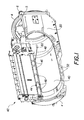
- Fig. 1 is a front isometric view of an internal drum assembly including the present invention.
- Fig. 2 is a front isometric view of the present invention.
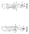
- Figs. 3 a and 3b are isometric views of the finger-carriage assembly of the invention of Fig. 1.
- Fig. 4 is an isometric view of the present invention excluding film guides and some rollers to show internal components.
- Fig. 5 is a cross-sectional elevational view of the present invention with film entering.
- Figs. 6a and 6b are a cross-sectional elevational views of the present invention with film passing the film position sensor.
- Fig. 7 is a cross-sectional front view of the present invention with the trailing edge of the film at the last roller set.
- Figs. 8a and 8b are cross-sectional elevational views of the present invention with the fingers pushing the film into the imaging region of the cylinder.
- Fig. 9 is a cross-sectional elevational view of the present invention demonstrating the finger motor over travel.
- Figs. 10a and 10b are isometric views of the present invention showing the operation for one size film.
- Figs. 11a and 11b are isometric views of the present invention showing the operation for another size film.
- Fig. 12 is a rear isometric view of an internal drum assembly.
- Figure 12 is a rear isometric view of internal drum assembly including a film platen 20 and platen registration bar assembly 10 , a bar 2 attached to a pair of large gears 4 and five independently spring-loaded sliders 1 .
- a geared motor 3 actuated by control system 100 locates the bar by rotating the large gears, synchronized with a pair of gears 6 attached to a rod 5 .
- Assembly 10 is able to deskew films ranging in lengths from 18 cm. to 43 cm. and in widths of both 25 cm. and 36 cm.
- Assembly 10 is mounted for movement on a horizontally oriented concave curved film platen 20 having first and second horizontal edge regions 22 , 24 and third and fourth curved side regions 26, 28 connected between said first and second edge regions 22, 24 .
- the concave, curved film platen has a curved surface 30 defining a film path from first edge region 22 to second edge region 24.
- Platen 20 is preferably cast aluminum and has arcuate slots 32 in which said sliders 1 are slidably mounted. When a film is fully positioned on platen 20 bar 2 and sliders 1 establish the location of the leading edge of the film.
- a film 40 has been positioned on curved platen 20 by film (media) feed device 42 which includes feed roller set 44 and independently spring loaded fingers 46 .
- film (media) feed device 42 which includes feed roller set 44 and independently spring loaded fingers 46 .
- fingers 46 have been rotated into the film path and moved vertically through segmented roller set 44 to push film 40 into the scanning region of platen 20 .
- Scanning is represented by laser beam 48 which is rotated about axis 50 and translated the length of film 40 to expose film 40 in a raster pattern of a digital image.
- FIG. 2 is an isometric view of film feed device 42 including a platen finger assembly.
- Film feed device 42 includes leading edge guide 50 , film guide 52 , segmented drive roller 54 , drive roller 56 , rollers 58 , 60 , film position sensor 61 , segmented roller set 44 including rollers 64 , 66 , roller drive stepper motor 68 , linear stepper motor 70 coupled to bracket 72 .
- Using a leading edge guide 50 in combination with a solid drive roller 56 acting as an entrance guide reduces the probability of film scratching.
- a segmented drive roller 54 prevents the trailing portion of the film from slapping the leading edge guide 52 after leaving the vertical transport.
- the film enters a roller set 58 , 60 which is necessary to maintain the roller set pitch required to transport smaller film sizes, and is then constrained by another film guide 52 .
- the two film guides 50 , 52 constrain the film path to properly actuate the film position sensor 62 and ensure proper feeding into the segmented roller set 64 , 66 .
- the stepper motor 63 driving the rollers stops shortly after the trailing edge of film 40 passes the sensor 61 .
- a linear stepper motor pulls a bracket 72 downward.
- the bracket 72 interlocks with the finger carriages 74 .
- Drawer slides 76 constrain the bracket's motion vertically.
- An important advantage of this invention is the ability to produce a borderless image in a small diameter scanning cylinder by using five independently spring loaded fingers to push the film out of the roller set and into the scanning region of the platen.
- Figures 3a and 3b show a platen finger assembly including a finger 46 rotatably mounted on pin 80 of carriage 74.
- Carriage 74 slides on shafts 82, torsion spring 84 loading the finger 46 against the carriage 74.
- This spring 84 spring-loads the finger 46 into the film path.
- the finger 46 rotates about a pin 80 .
- the cam surface 85 on the finger serves to rotate the finger 46 out of the film path at the home position.
- Two shafts 82 constrain each carriage 74 to translate linearly in the vertical direction (parallel to the film path).
- An extension spring 86 provides the independent spring-loading aspect of the mechanism. This spring 86 acts as a tolerance accumulator, allowing all the intended fingers 46 (number depends on film width) to apply pressure to the film.
- Figure 4 shows the platen finger assembly without the film guides and some of the rollers.
- the bottom segmented idler roller 64 has a larger diameter to allow the fingers 46 to pass through the segmented regions as shown.
- the fingers 46 rotate out of the film path when the flag 90 interrupts the finger home sensor 62 .
- the platen finger assembly operates using one rotational stepper 68 to turn the rollers, one linear stepper 70 to actuate the fingers, and two sensors 61 , 62 (one 61 for film detection and one 62 for finger position).
- the sequence of operations begins with input from software indicating a film is approaching the platen as a result of a signal from sensor 61.
- the rotational stepper motor 68 turns the rollers with a tangential velocity of, for example 20 inches per second.
- Figure 5 shows a cross-sectional view of the platen finger assembly with a film 40 approaching the film position sensor 61 .
- the entrance guide roller 56 ensures a scratch free handoff between the vertical assembly and the platen 20.
- the linear stepper motor 70 holds the fingers 46 in the home position, indicated by the flag 71 attached to the bracket 72 blocking the optical sensor 62 .
- carriages 74 interlock with the bracket 72 and transport the fingers 46, which are spring loaded with torsion springs 74.
- the fingers 46 are in the home position, which is outside of the film path, behind the film guide.
- the film 40 is actuating the film position sensor 62 in Figure 6a.
- the exit guide roller 54 prevents the tail edge of the film from slapping against a sheet metal edge or bend, which helps eliminate scratches on the film surface.
- the rollers continue to turn as software waits for the film 40 to clear the film position sensor 61 , see Figure 6b.
- Control system 100 continues to turn the rollers until the trailing edge reaches the last roller set 64 , 66 based on timing, see Figure 7.
- the sequence of operations and timing used to determine trailing edge placement in the roller set 64 , 66 is independent of film size, since the film position sensor 61 checks for the trailing edge of the film 40 .
- the rollers 64, 66 stop turning and the linear stepper motor 70 moves the finger-carriages 74 downward, such that the fingers 46 rotate into the film path and the bottom surface of fingers 46 is perpendicular to the film 40 as depicted in Figure 8a.
- the linear stepper motor 70 continues to pull the fingers 46 downward, which travel linearly without further rotation, and the fingers 46 register with the platen 40 surface as shown in Figure 8b pushing film 40 out of the nip of rollers 64 , 66 so that film 40 can be exposed to a borderless image.
- the linear stepper motor 70 has a small over travel, which allows each finger 46 to individually register to the platen 40 surface (via the spring loaded constraint with the bracket 74 ).
- the gap 110 in figure 9 occurs as the bracket 74 continues to travel downward after the finger registers with the platen surface. This additional travel made by the bracket 74 is possible with the use of the use of the extension springs 86 .
- the platen finger assembly contains five fingers 46 in an attempt to apply a distributed force to the trailing edge of the film 40 .
- Figure 10 shows the operation for 25 cm film for example, and Figure 11 for 36 cm wide film, for example.
Landscapes
- Engineering & Computer Science (AREA)
- Multimedia (AREA)
- Signal Processing (AREA)
- Facsimile Scanning Arrangements (AREA)
- Projection-Type Copiers In General (AREA)
- Laser Beam Printer (AREA)
Abstract
In an internal drum scanner assembly having a curved platen for
supporting media during exposure by a laser image scanner, media positioning
apparatus comprising: a media feed device for feeding media onto the curved
platen; and an assembly for pushing the media out of the feed device into the
scanning region of the platen so that a borderless image can be produced on the
media.
Description
- This invention relates in general to internal drum scanner assemblies and laser imaging systems incorporating such scanner assemblies. In particular, the present invention relates to a mechanism for aligning film into a scanning position in an internal drum type scanner assembly, suitable for use in a medical imaging system, where the entire film is accessible to a laser so that borderless images can be produced.
- Laser imaging systems are commonly used to produce photographic images from digital image data generated by magnetic resonance (MR), computed tomography (CT) or other types of medical image scanners. Systems of this type typically include a continuous tone laser imager for exposing the image on photosensitive film, a film processor for developing the film, and control subsystems for coordinating the operation of the laser imager and the film processor.
- The digital image data is a sequence of digital image values representative of the scanned image. Image processing electronics within the control subsystem processes the image data values to generate a sequence of digital laser drive values (i.e., exposure values), which are input to a laser scanner. The laser scanner is responsive to the digital laser drive values for scanning across the photosensitive film in a raster pattern for exposing the image on the film.
- The continuous-tone images used in the medical imaging field have very stringent image-quality requirements. A laser imager printing onto transparency film exposes an image in a raster format, the line spacing of which must be controlled to better than one micrometer. In addition, the image must be uniformly exposed such that the observer cannot notice any artifacts. In the case of medical imaging, the observers are professional image analysts (e.g., radiologists).
- Film exposure systems are used to provide exposure of the image on photosensitive film. Known film exposure systems include a linear translation system and a laser or optical scanning system. The laser scanning system includes a laser scanner with unique optical configurations (i.e., lenses and mirrors) for exposure of the image onto the film. The linear translation system provides for movement of the laser scanning system in a direction perpendicular to the scanning direction, such that a full image may be scanned on a piece of photosensitive film.
- In an internal drum type laser scanner assembly, a piece of film is positioned onto a film platen, wherein the film platen has a partial cylindrical or partial drum shape. The photosensitive film is positioned against the film platen. The laser or optical scanning system is positioned at the center of curvature of the photosensitive film for scanning a scan line across the photosensitive film surface. A linear translation system moves the laser or optical scanning system lengthwise along a longitudinal axis as defined by the center of curvature of the film to expose an entire image onto the film.
- The film may be fed onto the film platen utilizing a film transport system which often incorporates a plurality of feed rollers. Once the piece of photosensitive film is fed onto the film platen, the film must be held tight against the curved surface of the film platen, and centered and aligned into a scanning position in order for an image to be correctly exposed onto the photosensitive film. Any skew of the film must also be removed. Often such methods and mechanisms for aligning and centering a piece of film on the internal surface of the film platen require multiple complex mechanical and electrical components and control systems.
- U.S. Pat. No. 5,956,071, issued Sep. 21, 1999, inventors Mattila et al., and U.S. Patent No. 6,342,914, issued Jan. 29, 2002, inventors Johnson et al. disclose positioning a film into a scanning position on a curved film platen in an internal drum scanner assembly. After the leading edge of the film is properly positioned, the rear edge is held in the nip of feed rollers during film scanning by a laser. Thus, a narrow border of the film in the film nip cannot be imaged. It is thus desirable to provide an internal drum scanner that can produce a borderless film.
- According to the present invention, there is provided a solution to these problems.
- According to a feature of the present invention, there is provided in an internal drum scanner assembly having a curved platen for supporting media during exposure by a laser image scanner, media positioning apparatus comprising: a media feed device for feeding media onto said curved platen; and an assembly for pushing said media out of said feed device into the scanning region of said platen so that a borderless image can be produced on said media.
- The invention has the following advantages.
- 1. An internal drum scanner assembly is provided that can produce a borderless film.
-
- Fig. 1 is a front isometric view of an internal drum assembly including the present invention.
- Fig. 2 is a front isometric view of the present invention.
- Figs. 3 a and 3b are isometric views of the finger-carriage assembly of the invention of Fig. 1.
- Fig. 4 is an isometric view of the present invention excluding film guides and some rollers to show internal components.
- Fig. 5 is a cross-sectional elevational view of the present invention with film entering.
- Figs. 6a and 6b are a cross-sectional elevational views of the present invention with film passing the film position sensor.
- Fig. 7 is a cross-sectional front view of the present invention with the trailing edge of the film at the last roller set.
- Figs. 8a and 8b are cross-sectional elevational views of the present invention with the fingers pushing the film into the imaging region of the cylinder.
- Fig. 9 is a cross-sectional elevational view of the present invention demonstrating the finger motor over travel.
- Figs. 10a and 10b are isometric views of the present invention showing the operation for one size film.
- Figs. 11a and 11b are isometric views of the present invention showing the operation for another size film.
- Fig. 12 is a rear isometric view of an internal drum assembly.
- Figure 12 is a rear isometric view of internal drum assembly including a
film platen 20 and platenregistration bar assembly 10, abar 2 attached to a pair oflarge gears 4 and five independently spring-loaded sliders 1. A geared motor 3 actuated bycontrol system 100 locates the bar by rotating the large gears, synchronized with a pair ofgears 6 attached to arod 5.Assembly 10 is able to deskew films ranging in lengths from 18 cm. to 43 cm. and in widths of both 25 cm. and 36 cm. -
Assembly 10 is mounted for movement on a horizontally oriented concavecurved film platen 20 having first and secondhorizontal edge regions curved side regions second edge regions curved surface 30 defining a film path fromfirst edge region 22 tosecond edge region 24.Platen 20 is preferably cast aluminum and hasarcuate slots 32 in which said sliders 1 are slidably mounted. When a film is fully positioned onplaten 20bar 2 and sliders 1 establish the location of the leading edge of the film. - Referring now to Fig. 1, there is shown the internal drum assembly of Fig. 12 form the front and including an embodiment of the present invention. As shown, a
film 40 has been positioned oncurved platen 20 by film (media)feed device 42 which includesfeed roller set 44 and independently spring loadedfingers 46. As will be described in greater detail below,fingers 46 have been rotated into the film path and moved vertically through segmented roller set 44 to pushfilm 40 into the scanning region ofplaten 20. Scanning is represented bylaser beam 48 which is rotated aboutaxis 50 and translated the length offilm 40 to exposefilm 40 in a raster pattern of a digital image. - Figure 2 is an isometric view of
film feed device 42 including a platen finger assembly.Film feed device 42 includes leadingedge guide 50,film guide 52, segmenteddrive roller 54,drive roller 56,rollers film position sensor 61, segmentedroller set 44 includingrollers drive stepper motor 68,linear stepper motor 70 coupled tobracket 72. Using a leadingedge guide 50 in combination with asolid drive roller 56 acting as an entrance guide reduces the probability of film scratching. A segmenteddrive roller 54 prevents the trailing portion of the film from slapping the leadingedge guide 52 after leaving the vertical transport. The film enters aroller set film guide 52. The two film guides 50, 52 constrain the film path to properly actuate thefilm position sensor 62 and ensure proper feeding into the segmented roller set 64, 66. The stepper motor 63 driving the rollers stops shortly after the trailing edge offilm 40 passes thesensor 61. A linear stepper motor pulls abracket 72 downward. Thebracket 72 interlocks with thefinger carriages 74. Drawer slides 76, constrain the bracket's motion vertically. - An important advantage of this invention is the ability to produce a borderless image in a small diameter scanning cylinder by using five independently spring loaded fingers to push the film out of the roller set and into the scanning region of the platen.
- Figures 3a and 3b show a platen finger assembly including a
finger 46 rotatably mounted onpin 80 ofcarriage 74.Carriage 74 slides onshafts 82,torsion spring 84 loading thefinger 46 against thecarriage 74. Thisspring 84 spring-loads thefinger 46 into the film path. Thefinger 46 rotates about apin 80. Thecam surface 85 on the finger serves to rotate thefinger 46 out of the film path at the home position. Twoshafts 82 constrain eachcarriage 74 to translate linearly in the vertical direction (parallel to the film path). Anextension spring 86 provides the independent spring-loading aspect of the mechanism. Thisspring 86 acts as a tolerance accumulator, allowing all the intended fingers 46 (number depends on film width) to apply pressure to the film. - Figure 4 shows the platen finger assembly without the film guides and some of the rollers. The bottom segmented
idler roller 64 has a larger diameter to allow thefingers 46 to pass through the segmented regions as shown. Thefingers 46 rotate out of the film path when theflag 90 interrupts thefinger home sensor 62. - The platen finger assembly operates using one
rotational stepper 68 to turn the rollers, onelinear stepper 70 to actuate the fingers, and twosensors 61, 62 (one 61 for film detection and one 62 for finger position). The sequence of operations begins with input from software indicating a film is approaching the platen as a result of a signal fromsensor 61. Therotational stepper motor 68 turns the rollers with a tangential velocity of, for example 20 inches per second. Figure 5 shows a cross-sectional view of the platen finger assembly with afilm 40 approaching thefilm position sensor 61. Theentrance guide roller 56 ensures a scratch free handoff between the vertical assembly and theplaten 20. Thelinear stepper motor 70 holds thefingers 46 in the home position, indicated by theflag 71 attached to thebracket 72 blocking theoptical sensor 62. As mention earlier,carriages 74 interlock with thebracket 72 and transport thefingers 46, which are spring loaded with torsion springs 74. Thefingers 46 are in the home position, which is outside of the film path, behind the film guide. - The
film 40 is actuating thefilm position sensor 62 in Figure 6a. Theexit guide roller 54 prevents the tail edge of the film from slapping against a sheet metal edge or bend, which helps eliminate scratches on the film surface. The rollers continue to turn as software waits for thefilm 40 to clear thefilm position sensor 61, see Figure 6b.Control system 100 continues to turn the rollers until the trailing edge reaches the last roller set 64, 66 based on timing, see Figure 7. The sequence of operations and timing used to determine trailing edge placement in the roller set 64, 66 is independent of film size, since thefilm position sensor 61 checks for the trailing edge of thefilm 40. - The
rollers linear stepper motor 70 moves the finger-carriages 74 downward, such that thefingers 46 rotate into the film path and the bottom surface offingers 46 is perpendicular to thefilm 40 as depicted in Figure 8a. Thelinear stepper motor 70 continues to pull thefingers 46 downward, which travel linearly without further rotation, and thefingers 46 register with theplaten 40 surface as shown in Figure8b pushing film 40 out of the nip ofrollers film 40 can be exposed to a borderless image. - The
linear stepper motor 70 has a small over travel, which allows eachfinger 46 to individually register to theplaten 40 surface (via the spring loaded constraint with the bracket 74). Thegap 110 in figure 9 occurs as thebracket 74 continues to travel downward after the finger registers with the platen surface. This additional travel made by thebracket 74 is possible with the use of the use of the extension springs 86. - The platen finger assembly contains five
fingers 46 in an attempt to apply a distributed force to the trailing edge of thefilm 40. Experimental results indicated that a solid finger across the entire trailing edge of the film is optimal and support is required near the comers. This design ensures that there are at least threefingers 46 on each film size, one in the middle and near each comer. All fivefingers 46 engage the film for film widths of 36 cm for example. Figure 10 shows the operation for 25 cm film for example, and Figure 11 for 36 cm wide film, for example.
Claims (8)
- In an internal drum scanner assembly having a curved platen for supporting media during exposure by a laser image scanner, media positioning apparatus comprising:a media feed device for feeding media onto said curved platen; andan assembly for pushing said media out of said feed device into scanning region of said platen so that a borderless image can be produced on said media.
- The apparatus of claim 1 wherein said media feed device includes a pair of rollers which feed said media onto said curved platen such that said trailing edge of said media is located in the nip of said rollers and said assembly pushed media out of said nip into said scanning region of said platen.
- The apparatus of claim 1 wherein said assembly includes a plurality of platen finger assemblies which engage said trailing edge of said media to push said media into the scanning region of said platen.
- The apparatus of claim 3 wherein said plurality of platen finger assemblies include a smaller subset of said assemblies which image media of a first dimension and either said plurality of or a larger subset of said assemblies which engage media of a second larger dimension.
- The apparatus of claim 2 wherein said assembly includes a plurality of platen finger assemblies which engage said trailing edge of said media to push said media into the scanning region of said platen.
- The apparatus of claim 5 wherein each of said platen finger assemblies includes a spring loaded finger which is held out of said media path as said media is fed onto said curved platen, and is biased into said media path after passage of said media to engage the trailing edge of said media.
- The apparatus of claim 6 including an assembly for simultaneously moving said platen finger assemblies in a vertical direction to push said media out of the nip of said rollers.
- The apparatus of claim 6 wherein said rollers are segmented to allow said fingers to pass through said rollers.
Applications Claiming Priority (2)
| Application Number | Priority Date | Filing Date | Title |
|---|---|---|---|
| US10/376,964 US6812952B2 (en) | 2003-02-28 | 2003-02-28 | Platen finger assembly for an internal drum scanner |
| US376964 | 2003-02-28 |
Publications (1)
| Publication Number | Publication Date |
|---|---|
| EP1463291A1 true EP1463291A1 (en) | 2004-09-29 |
Family
ID=32824739
Family Applications (1)
| Application Number | Title | Priority Date | Filing Date |
|---|---|---|---|
| EP04075499A Withdrawn EP1463291A1 (en) | 2003-02-28 | 2004-02-16 | Platen finger assembly for an internal drum scanner |
Country Status (3)
| Country | Link |
|---|---|
| US (1) | US6812952B2 (en) |
| EP (1) | EP1463291A1 (en) |
| JP (1) | JP2004262239A (en) |
Citations (2)
| Publication number | Priority date | Publication date | Assignee | Title |
|---|---|---|---|---|
| US5956071A (en) * | 1997-09-29 | 1999-09-21 | Eastman Kodak Company | Mechanism for positioning film into a scanning position in an internal drum laser scanner assembly |
| US6342914B1 (en) * | 2000-08-28 | 2002-01-29 | Eastman Kodak Company | Film registration slides |
Family Cites Families (1)
| Publication number | Priority date | Publication date | Assignee | Title |
|---|---|---|---|---|
| US5436695A (en) * | 1994-03-17 | 1995-07-25 | Minnesota Mining And Manufacturing | Method and apparatus for loading thin film media |
-
2003
- 2003-02-28 US US10/376,964 patent/US6812952B2/en not_active Expired - Fee Related
-
2004
- 2004-02-04 JP JP2004027820A patent/JP2004262239A/en active Pending
- 2004-02-16 EP EP04075499A patent/EP1463291A1/en not_active Withdrawn
Patent Citations (2)
| Publication number | Priority date | Publication date | Assignee | Title |
|---|---|---|---|---|
| US5956071A (en) * | 1997-09-29 | 1999-09-21 | Eastman Kodak Company | Mechanism for positioning film into a scanning position in an internal drum laser scanner assembly |
| US6342914B1 (en) * | 2000-08-28 | 2002-01-29 | Eastman Kodak Company | Film registration slides |
Also Published As
| Publication number | Publication date |
|---|---|
| JP2004262239A (en) | 2004-09-24 |
| US20040169721A1 (en) | 2004-09-02 |
| US6812952B2 (en) | 2004-11-02 |
Similar Documents
| Publication | Publication Date | Title |
|---|---|---|
| JP2004114364A (en) | Optical writing device and image forming apparatus | |
| US5956071A (en) | Mechanism for positioning film into a scanning position in an internal drum laser scanner assembly | |
| US6437359B1 (en) | CR reader with vertical scanning | |
| US6812952B2 (en) | Platen finger assembly for an internal drum scanner | |
| US5572339A (en) | Film scanning system and method | |
| US11608237B2 (en) | System and method for automated sheet adjustment | |
| US6342914B1 (en) | Film registration slides | |
| US6825871B2 (en) | Film registration mechanism in an internal drum scanner | |
| JPH05167801A (en) | Scanner having floating backstop | |
| JP3338191B2 (en) | Book original transporter | |
| EP2458443A2 (en) | Imaging apparatus with moveable media guide | |
| JPH08237428A (en) | Scanner mounting device for electrostatic photoprinter | |
| JP2000206638A (en) | Sheet body carrying device | |
| EP1167784B1 (en) | Independently-tensioned multiplecable translation system | |
| US7110145B2 (en) | Scanning unit of image-recording apparatus | |
| JP3714884B2 (en) | Paper post-processing apparatus and image forming apparatus | |
| CN1126008C (en) | imaging device | |
| WO2008042273A1 (en) | Imaging apparatus with moveable entrance guide | |
| JP3753519B2 (en) | Image recording device | |
| JP2007060517A (en) | Image photographing system and image-forming device | |
| JP3966271B2 (en) | Image forming apparatus and positioning method of image forming apparatus and automatic document feeder | |
| JP2001518642A (en) | Film transport roller assembly | |
| US6011568A (en) | Printer processor sheet film registration and transfer mechanism | |
| EP1401187A2 (en) | Method and apparatus for incrementally displacing recording media in an imaging system. | |
| WO2008024213A1 (en) | A sheet scanning apparatus |
Legal Events
| Date | Code | Title | Description |
|---|---|---|---|
| PUAI | Public reference made under article 153(3) epc to a published international application that has entered the european phase |
Free format text: ORIGINAL CODE: 0009012 |
|
| AK | Designated contracting states |
Kind code of ref document: A1 Designated state(s): AT BE BG CH CY CZ DE DK EE ES FI FR GB GR HU IE IT LI LU MC NL PT RO SE SI SK TR |
|
| AX | Request for extension of the european patent |
Extension state: AL LT LV MK |
|
| 17P | Request for examination filed |
Effective date: 20050124 |
|
| AKX | Designation fees paid |
Designated state(s): DE FR |
|
| 17Q | First examination report despatched |
Effective date: 20050617 |
|
| STAA | Information on the status of an ep patent application or granted ep patent |
Free format text: STATUS: THE APPLICATION IS DEEMED TO BE WITHDRAWN |
|
| 18D | Application deemed to be withdrawn |
Effective date: 20051028 |