EP1463263B1 - Data communication frame generating method - Google Patents
Data communication frame generating method Download PDFInfo
- Publication number
- EP1463263B1 EP1463263B1 EP04015211A EP04015211A EP1463263B1 EP 1463263 B1 EP1463263 B1 EP 1463263B1 EP 04015211 A EP04015211 A EP 04015211A EP 04015211 A EP04015211 A EP 04015211A EP 1463263 B1 EP1463263 B1 EP 1463263B1
- Authority
- EP
- European Patent Office
- Prior art keywords
- code
- communication
- generating
- flag
- data
- Prior art date
- Legal status (The legal status is an assumption and is not a legal conclusion. Google has not performed a legal analysis and makes no representation as to the accuracy of the status listed.)
- Expired - Lifetime
Links
Images


Classifications
-
- H—ELECTRICITY
- H04—ELECTRIC COMMUNICATION TECHNIQUE
- H04L—TRANSMISSION OF DIGITAL INFORMATION, e.g. TELEGRAPHIC COMMUNICATION
- H04L47/00—Traffic control in data switching networks
- H04L47/10—Flow control; Congestion control
- H04L47/43—Assembling or disassembling of packets, e.g. segmentation and reassembly [SAR]
-
- H—ELECTRICITY
- H04—ELECTRIC COMMUNICATION TECHNIQUE
- H04L—TRANSMISSION OF DIGITAL INFORMATION, e.g. TELEGRAPHIC COMMUNICATION
- H04L61/00—Network arrangements, protocols or services for addressing or naming
- H04L61/50—Address allocation
- H04L61/5038—Address allocation for local use, e.g. in LAN or USB networks, or in a controller area network [CAN]
-
- H—ELECTRICITY
- H04—ELECTRIC COMMUNICATION TECHNIQUE
- H04L—TRANSMISSION OF DIGITAL INFORMATION, e.g. TELEGRAPHIC COMMUNICATION
- H04L9/00—Cryptographic mechanisms or cryptographic arrangements for secret or secure communications; Network security protocols
- H04L9/40—Network security protocols
-
- H—ELECTRICITY
- H04—ELECTRIC COMMUNICATION TECHNIQUE
- H04L—TRANSMISSION OF DIGITAL INFORMATION, e.g. TELEGRAPHIC COMMUNICATION
- H04L2101/00—Indexing scheme associated with group H04L61/00
- H04L2101/60—Types of network addresses
- H04L2101/618—Details of network addresses
- H04L2101/622—Layer-2 addresses, e.g. medium access control [MAC] addresses
-
- H—ELECTRICITY
- H04—ELECTRIC COMMUNICATION TECHNIQUE
- H04L—TRANSMISSION OF DIGITAL INFORMATION, e.g. TELEGRAPHIC COMMUNICATION
- H04L69/00—Network arrangements, protocols or services independent of the application payload and not provided for in the other groups of this subclass
- H04L69/30—Definitions, standards or architectural aspects of layered protocol stacks
- H04L69/32—Architecture of open systems interconnection [OSI] 7-layer type protocol stacks, e.g. the interfaces between the data link level and the physical level
- H04L69/322—Intralayer communication protocols among peer entities or protocol data unit [PDU] definitions
- H04L69/324—Intralayer communication protocols among peer entities or protocol data unit [PDU] definitions in the data link layer [OSI layer 2], e.g. HDLC
Definitions
- the control portion determines whether a data transmission request is occurring in its own communication device at the time when it receives data from another communication device. When a data transmission request is occurring, the control portion transmits the data of the data transmission request to another communication device before transferring the received data to the utilization portion. This eliminates the transmission delay corresponding to the time required for the utilization portion to process the received data, leading to improvement of the data transmission efficiency. This allows constructions of systems with lower communication rates than conventional ones in communication systems requiring guarantee of communication bands. Also, the data communication method is especially effective in described above systems for communicating audio data, moving picture data, etc. which seriously require the real-time property.
- the utilization portion 1 and the control portion 2 are composed of storage devices (ROM, RAM, hard disk, etc.) containing given program data.
- the functions performed by the control portion 2 are provided in the form of independent program data.
- the program data may be introduced through a recording medium such as a CD-ROM, floppy disk, etc., or may be introduced through communication.
- the address generating portion 21 arbitrarily generates an address code as the connection address by using random numbers (step S601). Then the address generating portion 21 determines whether the generated address code includes any section representing a code identical to the BOF or EOF flag code (step S602). When the determination made in step S602 shows that it includes a section of the same code, the address generating portion 21 returns to step S601 to generate an address code again. When the determination in step S602 shows absence of the same codes (or when the same section has been omitted), the address generating portion 21 determines the address code as the connection address (step S603).
- the IrDA communication system as an example. Accordingly the description was limited to the conversion of the connection address which is the only part the communication device can freely set in the IrDA communication system.
- the present invention can be used in asynchronous communication systems whether by radio or by wire.
- the communication frame generating method of the invention can similarly be applied to any parts that the communication devices can freely set, as well as to the address section for identification, also in asynchronous communication systems other than IrDA communication.
- the communication frame generating method of the invention can be applied to generation of communication frames used in other data communication methods.
Landscapes
- Engineering & Computer Science (AREA)
- Computer Networks & Wireless Communication (AREA)
- Signal Processing (AREA)
- Computer Security & Cryptography (AREA)
- Communication Control (AREA)
- Mobile Radio Communication Systems (AREA)
- Data Exchanges In Wide-Area Networks (AREA)
Description
- The present invention relates to a data communication method, a communication frame generating method, and medium on which program for executing the methods are recorded, and more particularly to, a communication frame generating method which prevents deterioration of data transmission (transfer) efficiency in asynchronous communications by radio and wire, and medium on which program for carrying out the data communication method and the communication frame generating method are recorded.
- In a communication device having a utilization portion for executing application processings and a control portion for executing communication protocol processings, the utilization portion and the control portion exchange data in data transmission/reception. In data transmission, the utilization portion sends a data transmission request to the control portion. The control portion receives the data transfer request and then performs the processing of transmitting the data. In data reception, the control portion receives data and transfers the received data to the utilization portion. The utilization portion receives and processes the transferred data from the control portion.
- Known data communication systems performed between the communication devices generally include the full duplex communication system and half duplex communication system.
- In the full duplex communication system, lines for transmission and reception are individually provided between communication devices, so that each communication device can freely transmit data without being affected by other communication devices. On the other hand, in the half duplex communication system, only a single line is provided between communication devices, so that a communication device cannot transmit data while the other communication device is transmitting data (therefore it receives the data).
- Hence, in the half duplex communication system, a "transmission right" indicating which of the communication devices is the subject of the data transmission is generally transmitted/received together with the data. The half duplex communication system thus defines that only a communication device having the transmission right can perform data transmission.
- Next, Fig. 8 shows an example of conventional data communication by half duplex performed between communication devices having utilization portions and control portions as described above. Fig. 8 is a diagram showing an example of a conventional communication sequence performed between communication devices A and B using the conventional data communication method. In Fig.8, the utilization portion in the communication device A is represented as "utilization portion A" and its control portion as "control portion A," and the utilization portion in the communication device B is represented as "utilization portion B" and its control portion as "control portion B."
- In the initial state, suppose that the transmission right resides in the communication device A and that a request for transmitting data B is occurring in the communication device B. First, the control portion A transmits only the transmission right to the control portion B, for it does not have a data transmission request at this time. The control portion B receives the transmission right sent from the control portion A, obtains the transmission-requested data B from the utilization portion B, and then transmits the data together with the transmission right to the control portion A. The control portion A then receives the data B and transmission right sent from the control portion B. Suppose that a request for transmitting data A is now occurring in the communication device A. In this case, the control portion A transfers the data B to the utilization portion A to preferentially process the data B transmitted from the control portion B. When receiving the data B, the utilization portion A processes the data B and then transfers the transmission-requested data A to the control portion A. Then, at last, the control portion A transmits the data A to the control portion B together with the transmission right.
- In this conventional communication device, as stated above, application processing to received data (the data B) has priority over its own data transmission request processing (the data A). Accordingly its data transmission is delayed by the time the utilization portion (the utilization portion A) takes to process the received data (shown by the thick arrow in Fig.8). In the case of systems for communications of audio data, moving picture data, etc. which seriously require the real-time property, such data transmission delay causes serious problems such as discontinuity of sound, blanks of image, etc.
- Conventionally, there have been two kinds of systems for connecting a plurality of communication devices: synchronous communication system and asynchronous communication system. In these communication systems, communication devices generally transmit/receive information etc. by using communication frames. In the asynchronous communication system, communication timing of communication frames transmitted/received between communication devices is not synchronized. Therefore the communication devices use communication frames including start and end flags at the beginning and end so that they can recognize the beginning and end of each communication frame.
- Fig.9 shows an example of structure of a communication frame used in the asynchronous communication. Referring to Fig.9, the communication frame used in the asynchronous communication includes address for identification of the destination communication device, data representing the transmitted information, etc., as well as the above-described start and end flags.
- When receiving the start flag, the communication device checks the following address and then processes the information to the end flag. The communication device thus recognizes the beginning and the end of the communication frame in accordance with the start and end flags. If any address code or data code identical to the start or end flag exists, the communication device may erroneously recognize the beginning or end of the communication frame. To avoid this problem, the communication device applies transparency control to codes representing the same codes as the start and end flags.
- In short, this transparency control means conversion of one value to another value. For example, if a code A identical to the start flag code is included in data, the code A is replaced by another code B (needless to say, the code B differs from the end flag code). The code after converted is generally provided with an extra identifier code so that the recipient can correctly recognize the data transparency-controlled on the sender. That is to say, the transparency-controlled code B is preceded by an identifier code to allow the recipient to determine whether the code B after transparency control is a transparency-controlled code B or the code B not transparency-controlled.
- The following is a specific example of the transparency control method, in which address, data, etc. which are identical to the start flag code "C0h" and the end flag code "C1h" are converted. The letter "h" represents hexadecimal.


- In the example above, the one-byte code "C0h" is converted into the two-byte code "7Dh E0h," and the one-byte code "C1h" is converted into the two-byte code "7Dh E1h." The part "7Dh" corresponds to the identifier code. Note that the code "7Dh" used as the identifier code is converted into the two-byte code "7Dh 5Dh." If the code "7Dh" is left unchanged, then data not subjected to transparency control (e.g., "E0h") will be erroneously restored on the recipient in the presence of a normal data code "7Dh."
- Thus the recipient can obtain the original codes by applying reverse transparency control only to codes preceded by the code "7Dh." The codes "E0h," "E1h," and "5Dh" not preceded by the code "7Dh" are thus not converted but left unchanged on the recipient.
- However, in the above-described transparency control method, a one-byte code is converted to a two-byte code. Then the communication frame becomes longer as a larger number of codes are subjected to the transparency control, and then the communication will take longer time than required.
- Document US-5586273 by D. Blair et. al., describes an HDLC asynchronous to synchronous converter applying the above described transparency control.
- The object of the present invention is to provide a communication frame generating method, according to
claim 1, which suppresses expansion of length of communication frames after transparency control by previously avoiding application of the transparency control to codes which can arbitrarily be set, such as identification address, to prevent deterioration of the data transmission (transfer) efficiency and a medium on which a program for executing that method is recorded. - To achieve the objects above, the present invention has the following features.
- A communication frame generating method for generating a communication frame used in communication in a communication device in an asynchronous communication system, which comprises the steps of:
- generating a start flag indicating the beginning of the communication frame and an end flag indicating the end of the communication frame (21);
- generating particular information stored between the start flag and the end flag in such a way that information which the communication device can arbitrarily set in the particular information does not contain any code identical to the flag codes of the start and end flags (21); and
- forming the communication frame on the basis of the start flag, the end flag, and the particular information (22).
- As stated above, information which can arbitrarily be set by the communication device in particular information in the communication frame is generated to exclude the same codes as flag codes of the start and end flags. In transparency control performed after the generation of the communication frame, this reduces the number of transparency-processed codes. This suppresses expansion of the length of the communication frame after the transparency control, thus preventing deterioration of the data transmission (transfer) efficiency.
- Preferably, according to a preferred embodiment, the step (21) of generating the particular information in the third aspect may comprise,
generating an arbitrary code of a predetermined number of bits by using random numbers (S601), and when the arbitrary code contains any code identical to the flag codes, repeatedly generating an arbitrary code by using random numbers (S602), and
determining the arbitrary code which does not contain any code identical to the flag codes as information to be generated (S603). - Also preferably, according to yet another preferred embodiment, the step (21) of generating the particular information in the third aspect may comprise
generating an arbitrary code of a predetermined number of bits by using random numbers (S701), and when the arbitrary code contains any code identical to the flag codes, converting the identical code to another predetermined code different from the flag codes (S702, S703), and
determining the arbitrary code which does not contain any code identical to the flag codes as information to be generated (S704). - More preferably, according yet another preferred embodiment, the information which the communication device can arbitrarily set in the particular information may be address information used for identification of the communication device.
- The invention is also directed to a recording medium, according to claim 5, on which a program executed in a communication device in an asynchronous communication system and for generating a communication frame used in communication is recorded, the program being computer-readable and for realizing on the communication device an operational environment comprising the steps of
generating a start flag indicating the beginning of the communication frame and an end flag indicating the end of the communication frame (21);
generating particular information stored between the start flag and the end flag in such a way that information which the communication device can arbitrarily set in the particular information does not contain any code identical to the flag codes of the start and end flags (21); and
forming the communication frame on the basis of the start flag, the end flag, and the particular information (22). - Preferably, according to preferred embodiment, the step (21) of generating the particular information may comprise,
generating an arbitrary code of a predetermined number of bits by using random numbers (S601) , and when the arbitrary code contains any code identical to the flag codes, repeatedly generating an arbitrary code by using random numbers (S602), and
determining the arbitrary code which does not contain any code identical to the flag codes as information to be generated (S603). - Also preferably, according to another preferred embodiment, the step (21) of generating the particular information may comprise
generating an arbitrary code of a predetermined number of bits by using random numbers (S701), and when the arbitrary code contains any code identical to the flag codes, converting the identical code to another predetermined code different from the flag codes (S702, S703), and
determining the arbitrary code which does not contain any code identical to the flag codes as information to be generated (S704). - Yet another preferred embodiment, more preferably, according to the information which the communication device can arbitrarily set in the particular information may be address information used for identification of the communication device.
- These and other objects, features, aspects and advantages of the present invention will become more apparent from the following detailed description of the present invention when taken in conjunction with the accompanying drawings.
-
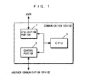
- Fig.1 is a block diagram showing the structure of a communication device using a data communication method according to a first embodiment of the present invention.
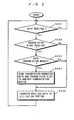
- Fig.2 is a flowchart showing an example of a communication protocol processing performed by the
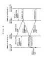
control portion 2 in Fig.1. - Fig.3 is a diagram showing an example of a communication sequence performed between communication devices A and B using the data communication method of the first embodiment of the present invention.
- Fig.4 is a block diagram showing the structure of a communication device using a communication frame generating method according to a second embodiment of the present invention.
- Fig.5 is a diagram showing the structure of a communication frame in the case of communication rates of 115.2 kbps or lower in IrDA communication standard.
- Fig. 6 is a flowchart showing an example of a connection address generating method performed by the
address generating portion 21 of Fig.4. - Fig.7 is a flowchart showing an example of the connection address generating method performed by the
address generating portion 21 of Fig.4. - Fig.8 is a diagram showing an example of a communication sequence performed between communication devices A and B using a conventional data communication method.
- Fig.9 is a diagram showing an example of the structure of a communication frame used in an asynchronous communication system.
- Fig.1 is a block diagram showing the structure of a communication device using the data communication method of the present invention. In Fig.1, the communication device using the data communication method of of the invention includes a
utilization portion 1, acontrol portion 2, and aCPU 3. - The
utilization portion 1 is the part corresponding to communication application, which sends a data transmission request to thecontrol portion 2, and obtains received data from thecontrol portion 2 and processes the data. Theutilization portion 1 is not specified to any service on communication protocol. That is to say, the user can use an arbitrary application program in theutilization portion 1. Thecontrol portion 2 is the part corresponding to the communication protocol, which provides control by receiving the data transmission request from theutilization portion 1 and transmitting the data, receiving data from another communication device and transferring the data to theutilization portion 1, etc. Thecontrol portion 2 performs data communication between communication devices according to the half duplex communication system. TheCPU 3 controls the entire communication device. - In typical hardware environment, the
utilization portion 1 and thecontrol portion 2 are composed of storage devices (ROM, RAM, hard disk, etc.) containing given program data. In this case, the functions executed by thecontrol portion 2 are provided in the form of independent program data. The program data may be introduced through a recording medium such as a CD-ROM, a floppy disk, etc., or may be introduced by communication. - Fig.2 is a flowchart showing an example of a communication protocol processing performed by the
control portion 2. Fig.3 is a diagram showing an example of a communication sequence performed between communication devices A and B. - First, referring to Fig.2, the
control portion 2 determines whether data is received from another communication device (step S201). When the determination made in step S201 shows reception of data, thecontrol portion 2 further determines whether a transmission right is also received (step S202). The determination in step S201 is repeatedly made until data is received from another communication device. - When the determination made in step S202 shows that the transmission right is not received, the
control portion 2 soon transfers the data received from another communication device to the utilization portion 1 (step S205). When the determination in step S202 shows reception of the transmission right, thecontrol portion 2 further determines whether a data transmission request is occurring in its own communication device (step S203). - When the determination in step S203 shows absence of the data transmission request, the
control portion 2 soon transfers the data received from another communication device to the utilization portion 1 (step S205). When the determination in step S203 shows occurrence of the data transmission request, thecontrol portion 2 first transmits the transmission-requested data (and the transmission right) to another communication device (step S204). Then, after the data transmission to another communication device has been finished, thecontrol portion 2 transfers the received data to the utilization portion 1 (step S205). - Next, referring to Fig. 3, the communication sequence performed by communication devices will be specifically described. In Fig.3, it is assumed that, in the initial state, the transmission right resides in the communication device A and that a transmission request for data B is occurring in the communication device B. In Fig.3, the utilization portion in the communication device A is represented as "utilization portion A" and its control portion as "control portion A," and the utilization portion of the communication device B is represented as "utilization portion B" and its control portion as "control portion B."
- First, the control portion A transmits only the transmission right to the control portion B since no data transmission request is now present in itself. The control portion B receives the transmission right sent from the control portion A, obtains the transmission-requested data B from the utilization portion B, and then transmits it with the transmission right to the control portion A. The control portion A receives the data B and transmission right sent from the control portion B.
- At the time when receiving the data B and the transmission right, the control portion A is receiving a transmission request for data A from the utilization portion A. Accordingly the control portion A first obtains the transmission-requested data A from the utilization portion A and transmits it to the control portion B together with the transmission right. After transmitting the data A, the control portion A transfers the received data B to the utilization portion A. The utilization portion A receives the transferred data B and starts processing.
- As described above, the control portion determines whether a data transmission request is occurring in its own communication device at the time when it receives data from another communication device. When a data transmission request is occurring, the control portion transmits the data of the data transmission request to another communication device before transferring the received data to the utilization portion. This eliminates the transmission delay corresponding to the time required for the utilization portion to process the received data, leading to improvement of the data transmission efficiency. This allows constructions of systems with lower communication rates than conventional ones in communication systems requiring guarantee of communication bands. Also, the data communication method is especially effective in described above systems for communicating audio data, moving picture data, etc. which seriously require the real-time property.
- Steps S201 to S203 in the flowchart of Fig. 2 showing processing performed by the
control portion 2 may be performed in a different order from that shown in the diagram. That is to say, as long as it receives data and the transmission right from another communication device and executes step S204 only when a data transmission request exists in itself, the order of steps S201 to S203 may be changed. - Next, a communication frame generating method of the present invention will now be described. While the communication frame generating method of the invention can be used in asynchronous communication systems whether they communicate by radio or by wire, an application to an Infrared Data Association (IrDA) system is described by way of example.
- Fig.4 is a block diagram showing the structure of a communication device using the communication frame generating method of the present invention. In Fig.4, the communication device using the communication frame generating method of the second embodiment of the invention includes a
utilization portion 1, acontrol portion 2, and aCPU 3. Thecontrol portion 2 includes anaddress generating portion 21, a communicationframe control portion 22, atransparency control portion 23, a reversetransparency control portion 24, a transmittingportion 25, and a receivingportion 26. - The
utilization portion 1 is the part corresponding to communication application, which sends requests for data transmission etc. to thecontrol portion 2. Thecontrol portion 2 is the part corresponding to communication protocol, which receives requests from theutilization portion 1 to provide control by finding a communication device, opening a link, transmitting/receiving data, etc. Theaddress generating portion 21 generates connection addresses used as identification codes in communication with other communication devices by using random numbers. The communicationframe control portion 22 generates communication frames in transmission, and analyzes received communication frames in reception. Thetransparency control portion 24 applies transparency control to the communication frames generated in the communicationframe control portion 22. The reversetransparency control portion 24 cancels transparency control applied to communication frames received. The transmittingportion 25 transmits communication frames after transparency control to other communication devices. The receivingportion 26 receives communication frames transmitted from other communication devices and outputs the communication frames to the reversetransparency control portion 24. TheCPU 3 controls the entirety of the communication device. - As mentioned above, in typical hardware environment, the
utilization portion 1 and thecontrol portion 2 are composed of storage devices (ROM, RAM, hard disk, etc.) containing given program data. In this case, the functions performed by thecontrol portion 2 are provided in the form of independent program data. The program data may be introduced through a recording medium such as a CD-ROM, floppy disk, etc., or may be introduced through communication. - First, operation of IrDA communication between the above communication devices will briefly be described.
- A communication device desiring to make a communication (hereinafter referred to as a starting station) finds another communication device as an object of the communication (hereinafter referred to as an answering station) and opens a link. Subsequently, the starting station arbitrarily sets a connection address used as an identification code in the communication. This connection address is an element included in the communication frame described later, together with information for connecting processing, user data, etc. The starting station then stores the connection address in the communication frame and transmits the communication frame, and the answering station identifies the connection address and receives and processes the communication frame only when it is destined to itself.
- Next, the structure of the communication frame in IrDA communication standard will be described referring to Fig.5. Fig.5 is a diagram showing the structure of a communication frame generated in the communication frame control portion 22 (in the case of communication rates of 115.2 kbps or lower).
- Referring to Fig.5, the communication frame includes, from its beginning, a BOF (Beginning Of Frame), connection address, control code section, information code section, FCS (Frame Check Sequence) , and EOF (End Of Frame). The BOF is a flag indicating the beginning of the communication frame. The control code section contains codes indicating type and order number of the data stored. The information code section contains user data. The FCS contains a code for error detection. The EOF is a flag indicating the end of the communication frame.
- In the structure of the communication frame, BOF and EOF are important flags for identifying the communication frame, and the codes used in the BOF and EOF flags should not exist in other codes. Hence, if the same codes as the BOF and EOF flag codes exist in the codes of the connection address, control code section, information code section, and FCS, the overlapping codes must previously be avoided by the transparency control described in the background art.
- While the codes other than the connection address cannot freely be set (or changed) by the communication device according to the IrDA communication system standard or an instruction from the user, the connection address can freely be set between the starting station and answering station when opening the link between the communication devices as described above. Accordingly, for the connection address, the application of the transparency control itself can be avoided in advance by setting it in such a way that it does not include the same codes as the BOF and EOF flag codes.
- The communication frame generating method of preferred embodiments of the invention for setting the connection address to exclude the same codes as the BOF and EOF flag codes will now be described referring to Figs. 6 and 7. Figs. 6 and 7 are flowcharts each showing an example of the connection address generating method performed in the
address generating portion 21 of Fig.4. - Now, a first method will be described referring to Fig.6.
- The
address generating portion 21 arbitrarily generates an address code as the connection address by using random numbers (step S601). Then theaddress generating portion 21 determines whether the generated address code includes any section representing a code identical to the BOF or EOF flag code (step S602). When the determination made in step S602 shows that it includes a section of the same code, theaddress generating portion 21 returns to step S601 to generate an address code again. When the determination in step S602 shows absence of the same codes (or when the same section has been omitted), theaddress generating portion 21 determines the address code as the connection address (step S603). - Next, another method will be described referring to Fig.7.
- The
address generating portion 21 arbitrarily generates an address code as the connection address by using random numbers (step S701). Then theaddress generating portion 21 determines whether the generated address code includes any section representing the same code as the BOF or EOF flag code (step S702). When the determination made in step S702 shows that it includes the same code section, theaddress generating portion 21 converts the same code section in the address code to another code prepared in advance (step S703). Then theaddress generating portion 21 determines the address code after converted as the connection address (step S704). When the determination in step S702 shows that it does not contain any same code section, theaddress generating portion 21 determines that address code unchanged as the connection address (step S704). In the conversion performed in step S703, both of a part representing the same code as the BOF flag code and a part representing the same code as the EOF flag code may be converted to another same code, or may be converted into different codes. - When the
address generating portion 21 performs this processing, it is possible to generate a special connection address not including the same codes as the BOF and EOF flag codes. Using a communication frame containing this special connection address in the communication prevents excessive application of the transparency control. - As described above, according to the communication frame generating method of the invention, sections representing the same codes as the BOF and EOF flag codes are converted into other codes in the process of generating the connection address. This reduces the number of codes to be subjected to the transparency processing in the transparency control after the generation of the communication frame. This suppresses extension of the length of the communication frame after transparency control, thus preventing deterioration of the data transmission (transfer) efficiency.
- The above embodiments have explained the IrDA communication system as an example. Accordingly the description was limited to the conversion of the connection address which is the only part the communication device can freely set in the IrDA communication system. However, as stated above, the present invention can be used in asynchronous communication systems whether by radio or by wire. Hence, the communication frame generating method of the invention can similarly be applied to any parts that the communication devices can freely set, as well as to the address section for identification, also in asynchronous communication systems other than IrDA communication.
- Further, needless to say, the communication frame generating method of the invention can be applied to generation of communication frames used in other data communication methods.
- While the invention has been described in detail, the foregoing description is in all aspects illustrative and not restrictive. It is understood that while numerous other modifications and variations can be devised, the invention is only limited by the scope of the appended claims.
Claims (8)
- A communication frame generating method for generating a communication frame, before a transparency control thereof is performed by a transparency control portion (23), in a communication device which outputs, in an asynchronous communication system, the communication frame transparency-controlled by the transparency control portion (23), comprising the steps of:generating a start flag indicating the. beginning of said communication frame and an end flag indicating the end of said communication frame; generating particular information stored between said start flag and said end flag in such a way that information which said communication device can arbitrarily set in said particular information does not contain any code identical to the flag codes of said start and end flags (21); andforming said communication frame before the transparency control on the basis of said start flag, said end flag, and said particular information (22).
- The communication frame generating method according to claim 1, wherein said step (21) of generating said particular information comprisesgenerating an arbitrary code of a predetermined number of bits by using random numbers (S601), and when said arbitrary code contains any code identical to said flag codes, repeatedly generating an arbitrary code by using random numbers (S602), anddetermining the arbitrary code which does not contain any code identical to said flag codes as information to be generated (S603).
- The communication frame generating method according to claim 1, wherein said step (21) of generating said particular information comprisesgenerating an arbitrary code of a predetermined number of bits by using random numbers (S701), and when said arbitrary code contains any code identical to said flag codes, converting the identical code to another predetermined code different from said flag codes (S702, S703), anddetermining the arbitrary code which does not contain any code identical to said flag codes as information to be generated (S704).
- The communication frame generating method according to one of the previous claims, wherein the information which said communication device can arbitrarily set in said particular information is address information used for identification of said communication device.
- A recording medium on which a program in a communication device which outputs a communication frame transparency-controlled by a transparency control portion (23) in an asynchronous communication system and for generating the communication frame before the transparency control portion (23) performs a transparency control is recorded, said program being computer-readable and for realizing on said communication device an operational environment comprising the steps ofgenerating a start flag indicating the beginning of said communication frame and an end flag indicating the end of said communication frame; generating particular information stored between said start flag and said end flag in such a way that information which said communication device can arbitrarily set in said particular information does not contain any code identical to the flag codes of said start and end flags (21); andforming said communication frame before the transparency control on the basis of said start flag, said end flag, and said particular information (22).
- The recording medium according to claim 5, wherein said step (21) of generating said particular information comprisesgenerating an arbitrary code of a predetermined number of bits by using random numbers (S601), and when said arbitrary code contains any code identical to said flag codes, repeatedly generating an arbitrary code by using random numbers (S602), anddetermining the arbitrary code which does not contain any code identical to said flag codes as information to be generated (S603).
- The recording medium according to claim 5, wherein said step (21) of generating said particular information comprisesgenerating an arbitrary code of a predetermined number of bits by using random numbers (S701), and when said arbitrary code contains any code identical to said flag codes, converting the identical code to another predetermined code different from said flag codes (S702, S703), anddetermining the arbitrary code which does not contain any code identical to said flag codes as information to be generated (S704).
- The recording medium according to one of claims 5 to 7, wherein the information which said communication device can arbitrarily set in said particular information is address information used for identification of said communication device.
Applications Claiming Priority (5)
| Application Number | Priority Date | Filing Date | Title |
|---|---|---|---|
| JP4382498 | 1998-02-25 | ||
| JP4382598 | 1998-02-25 | ||
| JP04382598A JP3369952B2 (en) | 1998-02-25 | 1998-02-25 | Communication frame generation method |
| JP10043824A JPH11243437A (en) | 1998-02-25 | 1998-02-25 | Data communication method |
| EP99102775A EP0944217A3 (en) | 1998-02-25 | 1999-02-23 | Methods for data communication and for generating communication frames |
Related Parent Applications (1)
| Application Number | Title | Priority Date | Filing Date |
|---|---|---|---|
| EP99102775A Division EP0944217A3 (en) | 1998-02-25 | 1999-02-23 | Methods for data communication and for generating communication frames |
Publications (3)
| Publication Number | Publication Date |
|---|---|
| EP1463263A2 EP1463263A2 (en) | 2004-09-29 |
| EP1463263A3 EP1463263A3 (en) | 2005-06-15 |
| EP1463263B1 true EP1463263B1 (en) | 2007-04-11 |
Family
ID=26383660
Family Applications (2)
| Application Number | Title | Priority Date | Filing Date |
|---|---|---|---|
| EP04015211A Expired - Lifetime EP1463263B1 (en) | 1998-02-25 | 1999-02-23 | Data communication frame generating method |
| EP99102775A Withdrawn EP0944217A3 (en) | 1998-02-25 | 1999-02-23 | Methods for data communication and for generating communication frames |
Family Applications After (1)
| Application Number | Title | Priority Date | Filing Date |
|---|---|---|---|
| EP99102775A Withdrawn EP0944217A3 (en) | 1998-02-25 | 1999-02-23 | Methods for data communication and for generating communication frames |
Country Status (5)
| Country | Link |
|---|---|
| US (1) | US6714540B1 (en) |
| EP (2) | EP1463263B1 (en) |
| KR (1) | KR100573820B1 (en) |
| CN (1) | CN1121770C (en) |
| DE (1) | DE69935812T2 (en) |
Families Citing this family (3)
| Publication number | Priority date | Publication date | Assignee | Title |
|---|---|---|---|---|
| JP3821006B2 (en) * | 2002-02-15 | 2006-09-13 | 株式会社デンソー | Communication system and receiving apparatus |
| CN104809100A (en) * | 2015-04-02 | 2015-07-29 | 上海新时达电气股份有限公司 | Text coding and decoding method and corresponding coding and decoding system |
| CN109814432B (en) * | 2018-12-18 | 2020-08-21 | 航天时代电子技术股份有限公司 | Human body follow-up control communication frame generation method and communication method |
Family Cites Families (14)
| Publication number | Priority date | Publication date | Assignee | Title |
|---|---|---|---|---|
| JPS594360A (en) | 1982-06-30 | 1984-01-11 | Fujitsu Ltd | System for preventing collision of inter-processor communication |
| JPS6074839A (en) * | 1983-09-30 | 1985-04-27 | Toshiba Corp | Repeater device |
| US4661902A (en) * | 1985-03-21 | 1987-04-28 | Apple Computer, Inc. | Local area network with carrier sense collision avoidance |
| US4827517A (en) * | 1985-12-26 | 1989-05-02 | American Telephone And Telegraph Company, At&T Bell Laboratories | Digital speech processor using arbitrary excitation coding |
| JPH02195744A (en) * | 1989-01-25 | 1990-08-02 | Nec Corp | Digital error detecting system |
| EP0441963A4 (en) * | 1989-07-07 | 1991-11-21 | Kabushiki Kaisha Yaskawa Denki Seisakusho | Absolute value encoder |
| US5335233A (en) * | 1990-12-31 | 1994-08-02 | International Business Machines Corporation | Data packet format |
| JPH06291760A (en) * | 1993-04-02 | 1994-10-18 | Mitsubishi Electric Corp | Digital signal processing system |
| JPH06291748A (en) | 1993-04-02 | 1994-10-18 | Hitachi Ltd | Half-duplex communication collision frequency reduction and offset prevention method |
| JPH0730560A (en) * | 1993-07-07 | 1995-01-31 | Fuji Xerox Co Ltd | LAN terminal |
| US5586273A (en) * | 1994-08-18 | 1996-12-17 | International Business Machines Corporation | HDLC asynchronous to synchronous converter |
| US5918024A (en) | 1996-05-08 | 1999-06-29 | Ericsson, Inc. | Method and apparatus for providing single channel communications |
| US6104505A (en) * | 1997-04-30 | 2000-08-15 | Ricoh Company, Ltd. | Method and apparatus for routing data information conveyed in a facsimile message |
| JP3439320B2 (en) | 1997-05-08 | 2003-08-25 | 松下電器産業株式会社 | Data communication method, data communication device, and data communication program recording medium |
-
1999
- 1999-02-19 US US09/251,906 patent/US6714540B1/en not_active Expired - Lifetime
- 1999-02-23 DE DE69935812T patent/DE69935812T2/en not_active Expired - Lifetime
- 1999-02-23 EP EP04015211A patent/EP1463263B1/en not_active Expired - Lifetime
- 1999-02-23 EP EP99102775A patent/EP0944217A3/en not_active Withdrawn
- 1999-02-25 KR KR1019990006235A patent/KR100573820B1/en not_active Expired - Fee Related
- 1999-02-25 CN CN99102458A patent/CN1121770C/en not_active Expired - Fee Related
Non-Patent Citations (1)
| Title |
|---|
| None * |
Also Published As
| Publication number | Publication date |
|---|---|
| US6714540B1 (en) | 2004-03-30 |
| DE69935812T2 (en) | 2007-12-27 |
| DE69935812D1 (en) | 2007-05-24 |
| CN1238615A (en) | 1999-12-15 |
| EP1463263A3 (en) | 2005-06-15 |
| KR19990072924A (en) | 1999-09-27 |
| EP0944217A2 (en) | 1999-09-22 |
| EP0944217A3 (en) | 2000-05-10 |
| KR100573820B1 (en) | 2006-04-26 |
| CN1121770C (en) | 2003-09-17 |
| EP1463263A2 (en) | 2004-09-29 |
Similar Documents
| Publication | Publication Date | Title |
|---|---|---|
| US7545807B2 (en) | Method for formatting signal in mobile communication system | |
| EP0308449B1 (en) | Transfer of messages in a multiplexed system | |
| US8078668B2 (en) | Method and device for processing a message in a communication network | |
| US20030163580A1 (en) | Data transmission protocol using short message service | |
| WO1995026097A1 (en) | Packet-switched facsimile network and method of operation | |
| US7197313B1 (en) | Method for allocating wireless resource in wireless communication system | |
| EP0999671A2 (en) | Transmission method and transmission device | |
| US6496487B2 (en) | Efficient full duplex simultaneous message transfer | |
| US6714540B1 (en) | Data communication method, communication frame generating method, and medium on which program for carrying out the methods are recorded | |
| US6463077B1 (en) | PHS data communication terminal adapter | |
| KR100226781B1 (en) | Method for recognizing node | |
| CA2035637A1 (en) | Method and apparatus for generating a 48-bit frame check sequence | |
| US7356024B1 (en) | Communication apparatus and communication method | |
| KR100961905B1 (en) | How to send and receive data | |
| US7212532B1 (en) | Message re-sending protocol for a wireless communications system | |
| EP1337928B1 (en) | Network and method for invisible proxy and hooking systems with wireless communication | |
| JPH11234347A (en) | Buffer management method and system in data communication | |
| EP1487178A1 (en) | Communication device and communication method | |
| KR100240633B1 (en) | Apparatus and method for wireless atm cell control system | |
| JP3369952B2 (en) | Communication frame generation method | |
| JP2000059460A (en) | Data communication method and data communication device | |
| JP2000332847A (en) | Protocol processing device | |
| JPH09154024A (en) | Color image data transmission method | |
| JPH04286437A (en) | Burst data communication method in tdma system ring type lan | |
| JP2002368834A (en) | Communication device and communication method |
Legal Events
| Date | Code | Title | Description |
|---|---|---|---|
| PUAI | Public reference made under article 153(3) epc to a published international application that has entered the european phase |
Free format text: ORIGINAL CODE: 0009012 |
|
| AC | Divisional application: reference to earlier application |
Ref document number: 0944217 Country of ref document: EP Kind code of ref document: P |
|
| AK | Designated contracting states |
Kind code of ref document: A2 Designated state(s): DE FI FR GB SE |
|
| PUAL | Search report despatched |
Free format text: ORIGINAL CODE: 0009013 |
|
| AK | Designated contracting states |
Kind code of ref document: A3 Designated state(s): DE FI FR GB SE |
|
| 17P | Request for examination filed |
Effective date: 20050818 |
|
| AKX | Designation fees paid |
Designated state(s): DE FI FR GB SE |
|
| GRAP | Despatch of communication of intention to grant a patent |
Free format text: ORIGINAL CODE: EPIDOSNIGR1 |
|
| GRAS | Grant fee paid |
Free format text: ORIGINAL CODE: EPIDOSNIGR3 |
|
| GRAA | (expected) grant |
Free format text: ORIGINAL CODE: 0009210 |
|
| AC | Divisional application: reference to earlier application |
Ref document number: 0944217 Country of ref document: EP Kind code of ref document: P |
|
| AK | Designated contracting states |
Kind code of ref document: B1 Designated state(s): DE FI FR GB SE |
|
| PG25 | Lapsed in a contracting state [announced via postgrant information from national office to epo] |
Ref country code: FI Free format text: LAPSE BECAUSE OF FAILURE TO SUBMIT A TRANSLATION OF THE DESCRIPTION OR TO PAY THE FEE WITHIN THE PRESCRIBED TIME-LIMIT Effective date: 20070411 |
|
| REG | Reference to a national code |
Ref country code: GB Ref legal event code: FG4D |
|
| REF | Corresponds to: |
Ref document number: 69935812 Country of ref document: DE Date of ref document: 20070524 Kind code of ref document: P |
|
| PG25 | Lapsed in a contracting state [announced via postgrant information from national office to epo] |
Ref country code: SE Free format text: LAPSE BECAUSE OF FAILURE TO SUBMIT A TRANSLATION OF THE DESCRIPTION OR TO PAY THE FEE WITHIN THE PRESCRIBED TIME-LIMIT Effective date: 20070711 |
|
| ET | Fr: translation filed | ||
| PLBE | No opposition filed within time limit |
Free format text: ORIGINAL CODE: 0009261 |
|
| STAA | Information on the status of an ep patent application or granted ep patent |
Free format text: STATUS: NO OPPOSITION FILED WITHIN TIME LIMIT |
|
| 26N | No opposition filed |
Effective date: 20080114 |
|
| PGFP | Annual fee paid to national office [announced via postgrant information from national office to epo] |
Ref country code: FR Payment date: 20130301 Year of fee payment: 15 Ref country code: GB Payment date: 20130220 Year of fee payment: 15 |
|
| GBPC | Gb: european patent ceased through non-payment of renewal fee |
Effective date: 20140223 |
|
| REG | Reference to a national code |
Ref country code: FR Ref legal event code: ST Effective date: 20141031 |
|
| PG25 | Lapsed in a contracting state [announced via postgrant information from national office to epo] |
Ref country code: GB Free format text: LAPSE BECAUSE OF NON-PAYMENT OF DUE FEES Effective date: 20140223 Ref country code: FR Free format text: LAPSE BECAUSE OF NON-PAYMENT OF DUE FEES Effective date: 20140228 |
|
| PGFP | Annual fee paid to national office [announced via postgrant information from national office to epo] |
Ref country code: DE Payment date: 20170214 Year of fee payment: 19 |
|
| REG | Reference to a national code |
Ref country code: DE Ref legal event code: R119 Ref document number: 69935812 Country of ref document: DE |
|
| PG25 | Lapsed in a contracting state [announced via postgrant information from national office to epo] |
Ref country code: DE Free format text: LAPSE BECAUSE OF NON-PAYMENT OF DUE FEES Effective date: 20180901 |