EP1463227A2 - Simple block space time transmit diversity using multiple spreading codes - Google Patents
Simple block space time transmit diversity using multiple spreading codes Download PDFInfo
- Publication number
- EP1463227A2 EP1463227A2 EP04015676A EP04015676A EP1463227A2 EP 1463227 A2 EP1463227 A2 EP 1463227A2 EP 04015676 A EP04015676 A EP 04015676A EP 04015676 A EP04015676 A EP 04015676A EP 1463227 A2 EP1463227 A2 EP 1463227A2
- Authority
- EP
- European Patent Office
- Prior art keywords
- data field
- data
- symbols
- channelization
- transmitter
- Prior art date
- Legal status (The legal status is an assumption and is not a legal conclusion. Google has not performed a legal analysis and makes no representation as to the accuracy of the status listed.)
- Granted
Links
Images


Classifications
-
- H—ELECTRICITY
- H04—ELECTRIC COMMUNICATION TECHNIQUE
- H04B—TRANSMISSION
- H04B1/00—Details of transmission systems, not covered by a single one of groups H04B3/00 - H04B13/00; Details of transmission systems not characterised by the medium used for transmission
- H04B1/69—Spread spectrum techniques
- H04B1/707—Spread spectrum techniques using direct sequence modulation
-
- H—ELECTRICITY
- H04—ELECTRIC COMMUNICATION TECHNIQUE
- H04B—TRANSMISSION
- H04B7/00—Radio transmission systems, i.e. using radiation field
- H04B7/02—Diversity systems; Multi-antenna system, i.e. transmission or reception using multiple antennas
-
- H—ELECTRICITY
- H04—ELECTRIC COMMUNICATION TECHNIQUE
- H04B—TRANSMISSION
- H04B7/00—Radio transmission systems, i.e. using radiation field
- H04B7/02—Diversity systems; Multi-antenna system, i.e. transmission or reception using multiple antennas
- H04B7/04—Diversity systems; Multi-antenna system, i.e. transmission or reception using multiple antennas using two or more spaced independent antennas
- H04B7/06—Diversity systems; Multi-antenna system, i.e. transmission or reception using multiple antennas using two or more spaced independent antennas at the transmitting station
- H04B7/0697—Diversity systems; Multi-antenna system, i.e. transmission or reception using multiple antennas using two or more spaced independent antennas at the transmitting station using spatial multiplexing
-
- H—ELECTRICITY
- H04—ELECTRIC COMMUNICATION TECHNIQUE
- H04L—TRANSMISSION OF DIGITAL INFORMATION, e.g. TELEGRAPHIC COMMUNICATION
- H04L1/00—Arrangements for detecting or preventing errors in the information received
- H04L1/02—Arrangements for detecting or preventing errors in the information received by diversity reception
- H04L1/06—Arrangements for detecting or preventing errors in the information received by diversity reception using space diversity
- H04L1/0618—Space-time coding
-
- H—ELECTRICITY
- H04—ELECTRIC COMMUNICATION TECHNIQUE
- H04L—TRANSMISSION OF DIGITAL INFORMATION, e.g. TELEGRAPHIC COMMUNICATION
- H04L1/00—Arrangements for detecting or preventing errors in the information received
- H04L1/02—Arrangements for detecting or preventing errors in the information received by diversity reception
- H04L1/06—Arrangements for detecting or preventing errors in the information received by diversity reception using space diversity
- H04L1/0618—Space-time coding
- H04L1/0631—Receiver arrangements
-
- H—ELECTRICITY
- H04—ELECTRIC COMMUNICATION TECHNIQUE
- H04L—TRANSMISSION OF DIGITAL INFORMATION, e.g. TELEGRAPHIC COMMUNICATION
- H04L25/00—Baseband systems
- H04L25/02—Details ; arrangements for supplying electrical power along data transmission lines
- H04L25/0202—Channel estimation
-
- H—ELECTRICITY
- H04—ELECTRIC COMMUNICATION TECHNIQUE
- H04L—TRANSMISSION OF DIGITAL INFORMATION, e.g. TELEGRAPHIC COMMUNICATION
- H04L25/00—Baseband systems
- H04L25/02—Details ; arrangements for supplying electrical power along data transmission lines
- H04L25/03—Shaping networks in transmitter or receiver, e.g. adaptive shaping networks
- H04L25/03828—Arrangements for spectral shaping; Arrangements for providing signals with specified spectral properties
- H04L25/03866—Arrangements for spectral shaping; Arrangements for providing signals with specified spectral properties using scrambling
Definitions
- the present invention relates to communications systems imploring code division multiple access (CDMA) techniques. More particularly, the present invention relates to a transmission diversity scheme which can be applied to a CDMA communication system
- Space-time block codes operate on a block of input symbols producing a matrix output over antennas and time.
- space-time transmit diversity systems have transmitted consecutive symbols simultaneously with their complex conjugates. This type of system, though may result in symbol overlap at the receiving end, with the amount of overlap being dependent on the length of the impulse response of the propagation channel.
- TDD time division duplex
- this symbol overlap will have to be accounted for in the joint detection receiver.
- the joint detector will have to estimate the transmitted symbols and their conjugates, resulting in an increase in complexity of the joint detection.
- the first data field having a first portion, D 1 , and a second portion, D 2 , is transmitted by the first antenna.
- a second data field is produced by modifying the first data field.
- the negation of the conjugate of D 2 , -D 2 *, is the first portion of the second data field and the conjugate of D 1 , D 1 *, is the second portion.
- the second data field is simultaneously transmitted by the second antenna.
- joint detection requires the use of two joint detectors at the receiver in a system employing two transmit diversity antennas.
- Each joint detection device estimates the data from one of the antennas. The estimated data is combined to produce the original data. Therefore, the receiver in such a system has a high complexity resulting in higher receiver expense.
- the present invention is a system and method for use in a CDMA communication system including a plurality of base stations and a user equipment (UE), each for communicating with each other.
- the base station has a transmitter which includes a first and second antenna for transmitting a data field of symbols.
- the first spreading device spreads the first data field using a first channelization code and the second spreading device spreads the second data field using a second channelization code, each channelization code being uniquely associated with one of the first and second antennas.
- the UE has a receiver for receiving a signal including the first and second spread data fields.
- the UE includes a joint detection device for detecting the symbols of the first and second data fields using the first and second channelization codes and a decoder for decoding the detected data fields to generate a single data field of symbols.
- Figure 1 is a block diagram of a prior art communication system employing space-time transmit diversity.
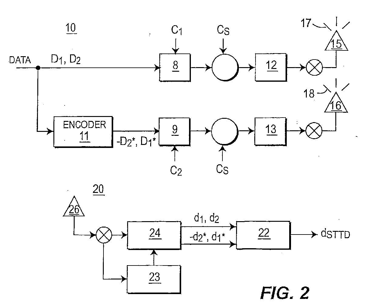
- FIG. 2 is a block diagram of a transmitter and receiver in a communication system in accordance with the preferred embodiment of the present invention.
- FIG. 3 is a flow diagram of the transmit diversity system of the present invention.
- Figure 4 is a graph of the performance of the transmit diversity system of the present invention.
- FIG. 5 is a block diagram of a transmitter and receiver in a communication system in accordance with an alternative embodiment of the present invention.
- Figure 6 is a flow diagram of an alternative transmit diversity system of the present invention.
- FIG 2 is a block diagram of a transmitter 10, preferably located at a base station, and a receiver 20, preferably located at a user equipment (UE), in a CDMA communication system in accordance with the preferred embodiment of the present invention.
- the transmitter 10 comprises a block encoder 11, a plurality of channelization devices 8, 9, a plurality of spreading sequence insertion devices 12, 13, and a plurality of antennas 15, 16.
- Figure 1 illustrates a transmitter comprising two (2) antennas, it should be apparent to those having skill in the art that more than two (2) antennas may be used, such as N antennas.
- a typical communication burst has two data fields separated by a midamble sequence.
- the same encoding procedure, as discussed in the following, for one data field is also performed on the other data field.
- Data to be transmitted by the transmitter 10 is produced by a data generator (not shown).
- the resulting data symbols (S 1 , S 2 , ...S N/2 ), (S N/2+1 , S N/2+2 , ..., S N ) of the first data field, which can be represented by sub-data fields D 1 and D 2 are input into the block encoder 11, preferably a block space-time transmit diversity (BSTTD) encoder.
- BSTTD block space-time transmit diversity
- the block encoder 11 encodes the input symbols and generates the complex conjugate of D 1 and the negation of the conjugate of D 2 : D 1 *, -D 2 *.
- the encoder 11 also changes the order of the symbols so that -D 2 * is ahead of D 1 *.
- an analogous encoding of the second data field is also performed.
- the data fields, D 1 , D 2 and -D 2 *, D 1 * are forwarded to a first and second channelization device 8, 9, respectively.
- the first channelization device 8 spreads the data blocks D 1 , D 2 by a first channelization code, and -D 2 *, D 1 * by the second channelization device 9 using a second different channelization code.
- Each of the spread data blocks from the first and second channelization devices 8, 9 are then scrambled by the scrambling code associated with the transmitter 10.
- the receiver 20 comprises a joint detection device (JD) 24, a BSTTD decoder 22, a channel estimation device 23 and an antenna 26.
- JD joint detection device
- BSTTD decoder 22 a BSTTD decoder 22
- channel estimation device 23 a channel estimation device 22
- the antenna 26 of the UE receives various RF signals including the communication bursts 17, 18 from the transmitter 10. The RF signals are then demodulated to produce a baseband signal.
- the baseband signal is then forwarded to the joint detection device 24 and the channel estimation device 23.
- the channel estimation device 23 provides channel information, such as channel impulse responses, to the joint detection device 24.
- the channel impulse response for each burst is determined using that burst's midamble sequence. Since each burst was transmitted using a different spreading code, the joint detection device 24 treats each burst as being transmitted by a different user. As a result, any joint detection device which can recover data from different transmitter sites may be used.
- Such j oint detection devices include zero forcing block linear equalizers, detection devices using Cholesky or approximate Cholesky decomposition, as well as many others.
- the joint detection device 24 estimates the data symbols of each of the bursts 17, 18 output by the transmitter antennas 15, 16 and forwards the estimates to the BSTTD decoder 22.
- the BSTTD decoder 22 coupled to the joint detection device 24, receives the estimated soft data symbols d 1 , d 2 and -d 2 *, d 1 * corresponding to the antennas 15, 16 and decodes the symbols to yield a single data field's soft symbols, d STTD .
- a data generator generates data to be transmitted to the receiver 20 (step 301). Each data field is separated into two sub-data fields D 1 , D 2 (step 302). The sub-data fields D 1 , D 2 are forwarded to the block encoder 11 and the first channelization device 8 (step 303). The sub-data fields forwarded to the block encoder 11 are encoded (step 304) and forwarded to the second channelization device 9 (step 305). Each channelization device 8, 9 spreads their respective data input using a separate channelization code associated with a respective antenna 15, 16 (step 306). The two spread signals are then scrambled, using the scrambling code associated with the base station (step 307) and transmitted to the receiver 20 over diversity antennas 15, 16 (step 308).
- the receiver 20 receives a RF communication signal including the two spread signals from the diversity antennas 15, 16 (step 309), demodulates the signal and forwards the demodulated signal to the channel estimation device 23 and joint detection device 24 (step 310).
- the received signal is processed by the channel estimation device 23 (step 311) and the channel information applied by the joint detection device 24 along with the channelization codes, to estimate the transmit symbols from the diversity antennas 15, 16 (step 312).
- the detected sub-data fields, corresponding to each diversity antenna 15, 16, are forwarded to the BSTTD decoder (step 313), which decodes the soft symbol sub-fields to yield a single data field's soft symbols, d STTD (step 314).
- Figure 5 is a block diagram of an alternative transmitter 40, preferably located at a base station, and a receiver 50, preferably located a user equipment (UE) in a communication system.
- the transmitter 40 comprises a plurality of channelization devices 48, 49, a plurality of spreading sequence insertion devices 42, 43, and a plurality of antennas 45, 46.
- Data to be transmitted by the transmitter 40 is produced by a data generator (not shown).
- the resulting data symbols (S 1 , S 2 , ...S N/2 ), (S N/2 +1, S N/2 +2, ..., S N ) of the first data field, which can be represented by sub-data fields D 1 and D 2 are input to a first and second channelization device 48,49, respectively.
- the first channelization device 8 spreads the data blocks D 1 , D 2 by a first channelization code
- the second channelization device 49 spreads the data blocks D 1 , D 2 by a second different channelization code.
- Each of the spread data blocks from the first and second channelization devices 48, 49 are scrambled by the scrambling code associated with the transmitter 40.
- the symbols are mixed with a first and second midamble through training sequence insertion devices 42, 43, producing two communication bursts 44, 45.
- the two bursts 44, 45 are modulated and simultaneously transmitted to the receiver 50 over antenna 46 and diversity antenna 47, respectively.
- the receiver 50 comprises a joint detection device (JD) 54, a decoder 22, a channel estimation device 53 and an antenna 51.
- the antenna 51 of the UE receives various RF signals including the communication bursts 44,45 from the transmitter 40.
- the RF signals are then demodulated to produce a baseband signal.
- the baseband signal is then forwarded to the joint detection device 54 and the channel estimation device 53.
- the joint detection device 54 coupled to the channel estimation device 53 and decoder 52, utilizes the channel information and the channelization codes to detect the soft data symbols d 1 , d 2 , in the received signal.
- the channel impulse response for each burst is determined using that burst's midamble sequence. Since each burst was transmitted using a different spreading code, the joint detection device 54 treats each burst as being transmitted by a different user.
- the joint detection device 54 estimates the data symbols of each of the signals 44, 45 output by the transmitter antennas 46, 47 and forwards the estimates to the decoder 52.
- the decoder 52 coupled to the joint detection device 54, receives the estimated soft data symbols d 1 , d 2 corresponding to the antennas 46, 47 and decodes the symbols to yield a single data field's soft symbols, d.
- a data generator generates data to be transmitted to the receiver 40 (step 601). Each data field is separated into two sub-data fields D 1 , D 2 (step 602). The sub-data fields D 1 , D 2 are forwarded to the first channelization device 48 and to the second channelization device 49 (step 603). Each channelization device 48, 49 spreads their respective data input using a separate channelization code associated with each antenna 46, 47 (step 604). The two spread signals are then scrambled, using the scrambling code associated with the base station (step 605) and transmitted to the receiver 50 over diversity antennas 46, 47 (step 606).
- the receiver 50 receives a RF communication signal including the two spread signals from the diversity antennas 46, 47 (step 607), demodulates the signal and forwards the demodulated signal to the channel estimation device 53 and joint detection device 54 (step 608).
- the received signal is processed by the channel estimation device 53 (step 609) and the channel information applied by the joint detection device 54 along with the channelization codes, to estimate the transmit symbols from the diversity antennas 46, 47 (step 610).
- the detected sub-data fields, corresponding to each diversity antenna 46, 47, are forwarded to the decoder 52 (step 611), which decodes the soft symbol sub-fields to yield a single data field's soft symbols, d STTD (step 612).
- each antenna has its own associated channelization code and midamble. If a block encoder is used, the data field transmitted by each of the antennas has a unique encoding, allowing the use of a single joint detector at the receiver.
- the BSTTD transmitter with two channelization codes of the present invention allows for the use of a cheaper and simpler method of transmit diversity.
- the use of different channelization codes per transmit antenna requires only one joint detection device at the receiver resulting in a less complex receiver system than those of the prior art.
- Figure 4 is a graph showing the raw BER of various block STTD decoders. The model is based on all the receivers using a block linear equalizer (BLE) based approach to JD. NTD means the single antenna case, i.e., no transmit diversity.
- STTD with 1 code is the traditional block STTD JD.
- STTD with 2 code is the disclosed block STTD transmitter.
- Simple STTD with 2 code is the transmission system disclosed in the alternative embodiment.
- the benefit of 2 codes for STTD can be summarized as follows: 1) there is up to a 0.5 dB gain at 0.01 raw Bit error rate over 1 code STTD; and 2) by eliminating the encoding block in simple STTD with 2 code, the performance degradation is only 0.2 dB at 0.1 raw BER and no degradation at 0.01 raw BER. The performance improvement over NTD is still 1.0 dB and 2.7 dB at 0.1 and 0.01 raw BER.
Landscapes
- Engineering & Computer Science (AREA)
- Computer Networks & Wireless Communication (AREA)
- Signal Processing (AREA)
- Power Engineering (AREA)
- Physics & Mathematics (AREA)
- Spectroscopy & Molecular Physics (AREA)
- Radio Transmission System (AREA)
- Mobile Radio Communication Systems (AREA)
- Arrangements For Transmission Of Measured Signals (AREA)
- Radar Systems Or Details Thereof (AREA)
- Radio Relay Systems (AREA)
- Circuits Of Receivers In General (AREA)
Abstract
Description
Claims (4)
- A base station comprising a first antenna (15) for transmitting a first communication burst and a second antenna (16) for transmitting a second communication burst, first means (8) for spreading provided data by using a first channelization code producing first spread data and second means (9) for spreading the same provided data by using a second channelization code producing second spread data, the first channelization code being different than the second channelization code, the base station characterized by comprising:third means (12) for inserting a first training sequence into the first spread data producing a first communication burst; andfourth means (13) for inserting a second training sequence into the second spread data producing a second communication burst.
- The base station of claim 1 wherein the first means (8) comprises a spreading device, the second means (9) comprises a spreading device, the third means (12) comprises a training sequence insertion device and the fourth means (13) comprises a training sequence insertion device.
- The base station of claims 1 or 2 further comprising means for scrambling the first and second spread data by a single scrambling code associated with the base station.
- The base station of claim 3 wherein the means for scrambling the first and second spread data comprises a first and second scrambling device for respectively scrambling the first and second spread data.
Priority Applications (3)
| Application Number | Priority Date | Filing Date | Title |
|---|---|---|---|
| EP09006756.2A EP2086147B9 (en) | 2000-12-07 | 2001-12-05 | Simple block space time transmit diversity using multiple spreading codes |
| DK09006756.2T DK2086147T3 (en) | 2000-12-07 | 2001-12-05 | Simple block for time and space transmission variation using multiple spreading codes |
| EP14171776.9A EP2779507A1 (en) | 2000-12-07 | 2001-12-05 | Simple block space time transmit diversity using multiple spreading codes |
Applications Claiming Priority (3)
| Application Number | Priority Date | Filing Date | Title |
|---|---|---|---|
| US25401300P | 2000-12-07 | 2000-12-07 | |
| US254013P | 2000-12-07 | ||
| EP01996123A EP1340334B1 (en) | 2000-12-07 | 2001-12-05 | Simple block space time transmit diversity using multiple spreading codes |
Related Parent Applications (1)
| Application Number | Title | Priority Date | Filing Date |
|---|---|---|---|
| EP01996123A Division EP1340334B1 (en) | 2000-12-07 | 2001-12-05 | Simple block space time transmit diversity using multiple spreading codes |
Related Child Applications (2)
| Application Number | Title | Priority Date | Filing Date |
|---|---|---|---|
| EP09006756.2A Division EP2086147B9 (en) | 2000-12-07 | 2001-12-05 | Simple block space time transmit diversity using multiple spreading codes |
| EP14171776.9A Division EP2779507A1 (en) | 2000-12-07 | 2001-12-05 | Simple block space time transmit diversity using multiple spreading codes |
Publications (3)
| Publication Number | Publication Date |
|---|---|
| EP1463227A2 true EP1463227A2 (en) | 2004-09-29 |
| EP1463227A3 EP1463227A3 (en) | 2005-04-27 |
| EP1463227B1 EP1463227B1 (en) | 2009-07-01 |
Family
ID=22962586
Family Applications (4)
| Application Number | Title | Priority Date | Filing Date |
|---|---|---|---|
| EP09006756.2A Expired - Lifetime EP2086147B9 (en) | 2000-12-07 | 2001-12-05 | Simple block space time transmit diversity using multiple spreading codes |
| EP04015676A Expired - Lifetime EP1463227B1 (en) | 2000-12-07 | 2001-12-05 | Simple block space time transmit diversity using multiple spreading codes |
| EP01996123A Expired - Lifetime EP1340334B1 (en) | 2000-12-07 | 2001-12-05 | Simple block space time transmit diversity using multiple spreading codes |
| EP14171776.9A Withdrawn EP2779507A1 (en) | 2000-12-07 | 2001-12-05 | Simple block space time transmit diversity using multiple spreading codes |
Family Applications Before (1)
| Application Number | Title | Priority Date | Filing Date |
|---|---|---|---|
| EP09006756.2A Expired - Lifetime EP2086147B9 (en) | 2000-12-07 | 2001-12-05 | Simple block space time transmit diversity using multiple spreading codes |
Family Applications After (2)
| Application Number | Title | Priority Date | Filing Date |
|---|---|---|---|
| EP01996123A Expired - Lifetime EP1340334B1 (en) | 2000-12-07 | 2001-12-05 | Simple block space time transmit diversity using multiple spreading codes |
| EP14171776.9A Withdrawn EP2779507A1 (en) | 2000-12-07 | 2001-12-05 | Simple block space time transmit diversity using multiple spreading codes |
Country Status (15)
| Country | Link |
|---|---|
| US (10) | US20020110108A1 (en) |
| EP (4) | EP2086147B9 (en) |
| JP (7) | JP2004524727A (en) |
| KR (8) | KR20100053690A (en) |
| CN (2) | CN100596048C (en) |
| AT (2) | ATE435535T1 (en) |
| AU (1) | AU2002227241A1 (en) |
| CA (3) | CA2635909C (en) |
| DE (2) | DE60139160D1 (en) |
| DK (3) | DK2086147T3 (en) |
| ES (3) | ES2230393T3 (en) |
| HK (1) | HK1200992A1 (en) |
| MX (1) | MXPA03005080A (en) |
| NO (2) | NO329514B1 (en) |
| WO (1) | WO2002047278A2 (en) |
Families Citing this family (28)
| Publication number | Priority date | Publication date | Assignee | Title |
|---|---|---|---|---|
| US20020110108A1 (en) * | 2000-12-07 | 2002-08-15 | Younglok Kim | Simple block space time transmit diversity using multiple spreading codes |
| EP1650892A1 (en) * | 2000-12-13 | 2006-04-26 | Interdigital Technology Corporation | Modified block space time transmit diversity decoder |
| US7095731B2 (en) | 2000-12-13 | 2006-08-22 | Interdigital Technology Corporation | Modified block space time transmit diversity encoder |
| WO2002100000A1 (en) * | 2001-06-04 | 2002-12-12 | Mitsubishi Denki Kabushiki Kaisha | Cdma transmission diversity apparatus |
| EP2521285B1 (en) * | 2001-09-12 | 2014-02-26 | Intel Mobile Communications GmbH | CDMA wireless systems |
| US7085332B2 (en) * | 2001-12-14 | 2006-08-01 | Ericsson, Inc. | Method and apparatus for two-user joint demodulation in a system having transmit diversity |
| JP3581357B2 (en) * | 2002-05-22 | 2004-10-27 | 松下電器産業株式会社 | Communication terminal apparatus and spreading code estimation method |
| US20040066739A1 (en) * | 2002-10-07 | 2004-04-08 | Koninklijke Philips Electronics N.V. | Simplified implementation of optimal decoding for COFDM transmitter diversity system |
| DE60322049D1 (en) | 2003-08-05 | 2008-08-21 | St Microelectronics Srl | Signal transmission method using antenna diversity and corresponding device |
| US7437135B2 (en) | 2003-10-30 | 2008-10-14 | Interdigital Technology Corporation | Joint channel equalizer interference canceller advanced receiver |
| US7400692B2 (en) | 2004-01-14 | 2008-07-15 | Interdigital Technology Corporation | Telescoping window based equalization |
| US20050175074A1 (en) * | 2004-02-11 | 2005-08-11 | Interdigital Technology Corporation | Wireless communication method and apparatus for performing multi-user detection using reduced length channel impulse responses |
| CN100488069C (en) * | 2005-05-27 | 2009-05-13 | 展讯通信(上海)有限公司 | Associated cell detecting method in TD-SCDMA system |
| US7916841B2 (en) * | 2006-09-29 | 2011-03-29 | Mediatek Inc. | Method and apparatus for joint detection |
| US7995641B2 (en) * | 2007-11-06 | 2011-08-09 | Telefonaktiebolaget Lm Ericsson (Publ) | Method and apparatus for code power parameter estimation for received signal processing |
| KR101603338B1 (en) | 2008-08-11 | 2016-03-15 | 엘지전자 주식회사 | Method and apparatus of transmitting information in wireless communication system |
| KR101597573B1 (en) | 2008-08-11 | 2016-02-25 | 엘지전자 주식회사 | Uplink transmission method of control information |
| KR20100019947A (en) | 2008-08-11 | 2010-02-19 | 엘지전자 주식회사 | Method of transmitting information in wireless communication system |
| KR101571566B1 (en) | 2008-08-11 | 2015-11-25 | 엘지전자 주식회사 | Method of transmitting control signal in wireless communication system |
| KR101646249B1 (en) | 2008-08-11 | 2016-08-16 | 엘지전자 주식회사 | Method and apparatus of transmitting information in wireless communication system |
| KR101243508B1 (en) | 2008-11-14 | 2013-03-20 | 엘지전자 주식회사 | Method and apparatus for signal transmission in wireless communication system |
| KR101225920B1 (en) | 2008-11-14 | 2013-01-24 | 엘지전자 주식회사 | Method and apparatus for information transmission in wireless communication system |
| US8737502B2 (en) | 2009-02-09 | 2014-05-27 | Qualcomm Incorporated | Multiplexing and coding schemes for multiple transmit antennas in a wireless communication system |
| KR20100091876A (en) | 2009-02-11 | 2010-08-19 | 엘지전자 주식회사 | Ue behavior for multi-antenna transmission |
| CN101667893B (en) * | 2009-09-29 | 2013-01-09 | 中国民航大学 | Virtual multi-input multi-output relay transmission method based on space-time block coding |
| US8543872B2 (en) * | 2011-01-24 | 2013-09-24 | Infineon Technologies Ag | Detecting and eliminating potential performance degradation caused by neighboring identical scrambling codes |
| CN107078854B (en) * | 2014-11-11 | 2020-07-07 | 瑞典爱立信有限公司 | Transmitting node, receiving node and method executed therein |
| US12684551B2 (en) * | 2021-09-23 | 2026-07-14 | Apple Inc. | Systems and methods for de-correlating coded signals in dual port transmissions |
Family Cites Families (49)
| Publication number | Priority date | Publication date | Assignee | Title |
|---|---|---|---|---|
| US656528A (en) * | 1898-05-27 | 1900-08-21 | Eugene Donard | Process of removing solvent vapors from wool. |
| US720175A (en) * | 1900-09-27 | 1903-02-10 | James M Dougherty | Bottle-capping machine. |
| GB9112898D0 (en) * | 1991-06-14 | 1991-07-31 | Digital Equipment Int | Communication networks |
| TW226003B (en) * | 1992-11-13 | 1994-07-01 | Toyo Kagaku Kk | |
| JPH08195703A (en) * | 1995-01-17 | 1996-07-30 | Toshiba Corp | Wireless communication device |
| EP1133074B1 (en) | 1995-07-19 | 2009-04-22 | Nec Corporation | CDMA diversity transmission system |
| US6134215A (en) | 1996-04-02 | 2000-10-17 | Qualcomm Incorpoated | Using orthogonal waveforms to enable multiple transmitters to share a single CDM channel |
| US6038263A (en) | 1997-07-31 | 2000-03-14 | Motorola, Inc. | Method and apparatus for transmitting signals in a communication system |
| DE19733336A1 (en) * | 1997-08-01 | 1999-02-18 | Siemens Ag | Method and radio station for data transmission |
| US6185258B1 (en) * | 1997-09-16 | 2001-02-06 | At&T Wireless Services Inc. | Transmitter diversity technique for wireless communications |
| CN1047047C (en) | 1997-10-05 | 1999-12-01 | 北京信威通信技术有限公司 | Method for establishing and holding synchronous code division multiple access communication chain |
| DE69832589T2 (en) | 1998-05-15 | 2006-08-10 | Sony Deutschland Gmbh | Transmitters and transmission methods that increase the flexibility of assigning codes |
| US6643338B1 (en) * | 1998-10-07 | 2003-11-04 | Texas Instruments Incorporated | Space time block coded transmit antenna diversity for WCDMA |
| EP0993129B1 (en) * | 1998-10-07 | 2007-01-24 | Texas Instruments Incorporated | Channel estimation in space time block coded transmit antenna diversity for WCDMA |
| US6154485A (en) * | 1998-10-19 | 2000-11-28 | Motorola, Inc. | Receiver in a wireless communications system for receiving signals having combined orthogonal transmit diversity and adaptive array techniques |
| EP0996234B1 (en) * | 1998-10-23 | 2006-06-28 | Sony Deutschland GmbH | Receiver architecture for a multi scrambling code transmission CDMA technique |
| FI108588B (en) * | 1998-12-15 | 2002-02-15 | Nokia Corp | Method and radio system for transmitting a digital signal |
| US6452916B1 (en) | 1999-01-04 | 2002-09-17 | Lucent Technologies Inc. | Space-time spreading method of CDMA wireless communication |
| US6728302B1 (en) * | 1999-02-12 | 2004-04-27 | Texas Instruments Incorporated | STTD encoding for PCCPCH |
| US6317411B1 (en) * | 1999-02-22 | 2001-11-13 | Motorola, Inc. | Method and system for transmitting and receiving signals transmitted from an antenna array with transmit diversity techniques |
| US6775260B1 (en) * | 1999-02-25 | 2004-08-10 | Texas Instruments Incorporated | Space time transmit diversity for TDD/WCDMA systems |
| US6862275B1 (en) * | 1999-02-26 | 2005-03-01 | Texas Instruments Incorporated | Cell selection with STTD and SSDT |
| JP2000261412A (en) * | 1999-03-06 | 2000-09-22 | Matsushita Electric Ind Co Ltd | Interference signal canceller |
| US6804311B1 (en) * | 1999-04-08 | 2004-10-12 | Texas Instruments Incorporated | Diversity detection for WCDMA |
| US6356528B1 (en) * | 1999-04-15 | 2002-03-12 | Qualcomm Incorporated | Interleaver and deinterleaver for use in a diversity transmission communication system |
| US6594473B1 (en) * | 1999-05-28 | 2003-07-15 | Texas Instruments Incorporated | Wireless system with transmitter having multiple transmit antennas and combining open loop and closed loop transmit diversities |
| EP1069707A1 (en) | 1999-07-13 | 2001-01-17 | Motorola, Inc. | Transmit diversity transmitter and receiver for radio communications systems |
| US6917597B1 (en) * | 1999-07-30 | 2005-07-12 | Texas Instruments Incorporated | System and method of communication using transmit antenna diversity based upon uplink measurement for the TDD mode of WCDMA |
| US6115406A (en) * | 1999-09-10 | 2000-09-05 | Interdigital Technology Corporation | Transmission using an antenna array in a CDMA communication system |
| JP3627589B2 (en) * | 1999-09-27 | 2005-03-09 | 豊田工機株式会社 | Pressure gauge |
| US6788661B1 (en) * | 1999-11-12 | 2004-09-07 | Nikia Networks Oy | Adaptive beam-time coding method and apparatus |
| US7254171B2 (en) * | 2000-01-20 | 2007-08-07 | Nortel Networks Limited | Equaliser for digital communications systems and method of equalisation |
| US6804307B1 (en) * | 2000-01-27 | 2004-10-12 | Telefonaktiebolaget Lm Ericsson (Publ) | Method and apparatus for efficient transmit diversity using complex space-time block codes |
| US6865237B1 (en) * | 2000-02-22 | 2005-03-08 | Nokia Mobile Phones Limited | Method and system for digital signal transmission |
| JP2001267982A (en) * | 2000-03-22 | 2001-09-28 | Matsushita Electric Ind Co Ltd | STTD encoding method and diversity transmitter |
| US7139324B1 (en) * | 2000-06-02 | 2006-11-21 | Nokia Networks Oy | Closed loop feedback system for improved down link performance |
| US6628702B1 (en) * | 2000-06-14 | 2003-09-30 | Qualcomm, Incorporated | Method and apparatus for demodulating signals processed in a transmit diversity mode |
| US7154958B2 (en) * | 2000-07-05 | 2006-12-26 | Texas Instruments Incorporated | Code division multiple access wireless system with time reversed space time block transmitter diversity |
| KR100374323B1 (en) * | 2000-08-10 | 2003-03-03 | 최종수 | Clustering Method for Rosette Scan Image |
| US7020175B2 (en) * | 2000-09-21 | 2006-03-28 | Motorola, Inc. | MMSE reception of DS-CDMA with transmit diversity |
| KR100401201B1 (en) * | 2000-10-06 | 2003-10-10 | 삼성전자주식회사 | Apparatus and method for determining use/nonuse an nb-tdd cdma mobile communication system |
| US20020110108A1 (en) * | 2000-12-07 | 2002-08-15 | Younglok Kim | Simple block space time transmit diversity using multiple spreading codes |
| US6748024B2 (en) * | 2001-03-28 | 2004-06-08 | Nokia Corporation | Non-zero complex weighted space-time code for multiple antenna transmission |
| US7471734B2 (en) * | 2001-04-26 | 2008-12-30 | Motorola, Inc. | Space-time transmit diversity scheme for time-dispersive propagation media |
| US7031419B2 (en) * | 2001-06-29 | 2006-04-18 | Nokia Corporation | Data transmission method and system |
| US7042955B2 (en) * | 2001-07-30 | 2006-05-09 | Lucent Technologies Inc. | Space time spreading and phase sweep transmit diversity |
| US7430191B2 (en) * | 2001-09-10 | 2008-09-30 | Qualcomm Incorporated | Method and apparatus for performing frequency tracking based on diversity transmitted pilots in a CDMA communication system |
| US7227905B2 (en) * | 2001-09-18 | 2007-06-05 | Lucent Technologies Inc. | Open-loop diversity technique for systems employing multi-transmitter antennas |
| US7085295B2 (en) * | 2001-10-04 | 2006-08-01 | Qualcomm Incorporated | Method and apparatus for searching for pilots over code space in a CDMA communication system |
-
2001
- 2001-11-15 US US09/999,287 patent/US20020110108A1/en not_active Abandoned
- 2001-12-05 AT AT04015676T patent/ATE435535T1/en not_active IP Right Cessation
- 2001-12-05 KR KR1020107008057A patent/KR20100053690A/en not_active Withdrawn
- 2001-12-05 KR KR1020077021548A patent/KR100860806B1/en not_active Expired - Fee Related
- 2001-12-05 MX MXPA03005080A patent/MXPA03005080A/en active IP Right Grant
- 2001-12-05 DE DE60139160T patent/DE60139160D1/en not_active Expired - Lifetime
- 2001-12-05 CA CA2635909A patent/CA2635909C/en not_active Expired - Fee Related
- 2001-12-05 DK DK09006756.2T patent/DK2086147T3/en active
- 2001-12-05 ES ES01996123T patent/ES2230393T3/en not_active Expired - Lifetime
- 2001-12-05 AU AU2002227241A patent/AU2002227241A1/en not_active Abandoned
- 2001-12-05 EP EP09006756.2A patent/EP2086147B9/en not_active Expired - Lifetime
- 2001-12-05 CA CA2776357A patent/CA2776357A1/en not_active Abandoned
- 2001-12-05 ES ES04015676T patent/ES2329677T3/en not_active Expired - Lifetime
- 2001-12-05 KR KR1020087006474A patent/KR100887276B1/en not_active Expired - Fee Related
- 2001-12-05 EP EP04015676A patent/EP1463227B1/en not_active Expired - Lifetime
- 2001-12-05 EP EP01996123A patent/EP1340334B1/en not_active Expired - Lifetime
- 2001-12-05 JP JP2002548883A patent/JP2004524727A/en active Pending
- 2001-12-05 KR KR1020037013883A patent/KR100811020B1/en not_active Expired - Fee Related
- 2001-12-05 DK DK01996123T patent/DK1340334T3/en active
- 2001-12-05 DK DK04015676T patent/DK1463227T3/en active
- 2001-12-05 KR KR1020087024873A patent/KR100972585B1/en not_active Expired - Fee Related
- 2001-12-05 CN CN200610131763A patent/CN100596048C/en not_active Expired - Lifetime
- 2001-12-05 AT AT01996123T patent/ATE281723T1/en not_active IP Right Cessation
- 2001-12-05 KR KR1020097019709A patent/KR101013926B1/en not_active Expired - Fee Related
- 2001-12-05 CA CA002430720A patent/CA2430720C/en not_active Expired - Fee Related
- 2001-12-05 EP EP14171776.9A patent/EP2779507A1/en not_active Withdrawn
- 2001-12-05 CN CNB01820127XA patent/CN1278507C/en not_active Expired - Lifetime
- 2001-12-05 KR KR1020097006552A patent/KR101025842B1/en not_active Expired - Fee Related
- 2001-12-05 KR KR10-2003-7007513A patent/KR100532821B1/en not_active Expired - Fee Related
- 2001-12-05 DE DE60106970T patent/DE60106970T2/en not_active Expired - Lifetime
- 2001-12-05 ES ES09006756.2T patent/ES2501915T3/en not_active Expired - Lifetime
- 2001-12-05 WO PCT/US2001/046603 patent/WO2002047278A2/en not_active Ceased
-
2002
- 2002-02-08 US US10/071,917 patent/US20020089953A1/en not_active Abandoned
- 2002-02-08 US US10/071,903 patent/US20020093927A1/en not_active Abandoned
- 2002-02-15 US US10/077,565 patent/US20020075832A1/en not_active Abandoned
- 2002-02-15 US US10/077,076 patent/US20020089955A1/en not_active Abandoned
- 2002-02-20 US US10/079,107 patent/US20020080746A1/en not_active Abandoned
- 2002-03-27 US US10/107,465 patent/US20020097699A1/en not_active Abandoned
-
2003
- 2003-05-28 NO NO20032435A patent/NO329514B1/en not_active IP Right Cessation
-
2005
- 2005-03-18 JP JP2005080007A patent/JP2005253095A/en active Pending
-
2009
- 2009-11-30 US US12/627,630 patent/US8311492B2/en not_active Expired - Fee Related
-
2010
- 2010-03-01 JP JP2010043951A patent/JP5066587B2/en not_active Expired - Fee Related
- 2010-03-18 NO NO20100401A patent/NO20100401L/en not_active Application Discontinuation
-
2011
- 2011-11-01 JP JP2011240094A patent/JP5575725B2/en not_active Expired - Fee Related
-
2012
- 2012-10-08 US US13/647,042 patent/US20130044734A1/en not_active Abandoned
-
2013
- 2013-11-22 JP JP2013242005A patent/JP5934170B2/en not_active Expired - Fee Related
-
2015
- 2015-02-04 HK HK15101225.8A patent/HK1200992A1/en unknown
- 2015-03-31 JP JP2015072571A patent/JP6220807B2/en not_active Expired - Lifetime
- 2015-04-21 US US14/692,415 patent/US20150229349A1/en not_active Abandoned
-
2016
- 2016-10-05 JP JP2016197266A patent/JP2017046353A/en not_active Withdrawn
Also Published As
Similar Documents
| Publication | Publication Date | Title |
|---|---|---|
| US8311492B2 (en) | Simple block space time transmit diversity using multiple spreading codes | |
| JP2008172814A (en) | Modified block space-time transmit diversity encoder |
Legal Events
| Date | Code | Title | Description |
|---|---|---|---|
| PUAI | Public reference made under article 153(3) epc to a published international application that has entered the european phase |
Free format text: ORIGINAL CODE: 0009012 |
|
| 17P | Request for examination filed |
Effective date: 20040702 |
|
| AC | Divisional application: reference to earlier application |
Ref document number: 1340334 Country of ref document: EP Kind code of ref document: P |
|
| AK | Designated contracting states |
Kind code of ref document: A2 Designated state(s): AT BE CH CY DE DK ES FI FR GB GR IE IT LI LU MC NL PT SE TR |
|
| RIN1 | Information on inventor provided before grant (corrected) |
Inventor name: KIM, YOUNGLOK Inventor name: ZEIRA, ARIELA |
|
| PUAL | Search report despatched |
Free format text: ORIGINAL CODE: 0009013 |
|
| AK | Designated contracting states |
Kind code of ref document: A3 Designated state(s): AT BE CH CY DE DK ES FI FR GB GR IE IT LI LU MC NL PT SE TR |
|
| RIC1 | Information provided on ipc code assigned before grant |
Ipc: 7H 04L 1/06 A Ipc: 7H 04L 25/02 B Ipc: 7H 04B 1/707 B Ipc: 7H 04B 7/26 B |
|
| AKX | Designation fees paid |
Designated state(s): AT BE CH CY DE DK ES FI FR GB GR IE IT LI LU MC NL PT SE TR |
|
| RAP1 | Party data changed (applicant data changed or rights of an application transferred) |
Owner name: INTERDIGITAL TECHNOLOGY CORPORATION |
|
| 17Q | First examination report despatched |
Effective date: 20051221 |
|
| GRAP | Despatch of communication of intention to grant a patent |
Free format text: ORIGINAL CODE: EPIDOSNIGR1 |
|
| GRAS | Grant fee paid |
Free format text: ORIGINAL CODE: EPIDOSNIGR3 |
|
| GRAA | (expected) grant |
Free format text: ORIGINAL CODE: 0009210 |
|
| AC | Divisional application: reference to earlier application |
Ref document number: 1340334 Country of ref document: EP Kind code of ref document: P |
|
| AK | Designated contracting states |
Kind code of ref document: B1 Designated state(s): AT BE CH CY DE DK ES FI FR GB GR IE IT LI LU MC NL PT SE TR |
|
| REG | Reference to a national code |
Ref country code: GB Ref legal event code: FG4D |
|
| REG | Reference to a national code |
Ref country code: CH Ref legal event code: EP |
|
| REG | Reference to a national code |
Ref country code: IE Ref legal event code: FG4D |
|
| REF | Corresponds to: |
Ref document number: 60139160 Country of ref document: DE Date of ref document: 20090813 Kind code of ref document: P |
|
| REG | Reference to a national code |
Ref country code: SE Ref legal event code: TRGR |
|
| REG | Reference to a national code |
Ref country code: DK Ref legal event code: T3 |
|
| REG | Reference to a national code |
Ref country code: ES Ref legal event code: FG2A Ref document number: 2329677 Country of ref document: ES Kind code of ref document: T3 |
|
| PG25 | Lapsed in a contracting state [announced via postgrant information from national office to epo] |
Ref country code: AT Free format text: LAPSE BECAUSE OF FAILURE TO SUBMIT A TRANSLATION OF THE DESCRIPTION OR TO PAY THE FEE WITHIN THE PRESCRIBED TIME-LIMIT Effective date: 20090701 |
|
| PG25 | Lapsed in a contracting state [announced via postgrant information from national office to epo] |
Ref country code: PT Free format text: LAPSE BECAUSE OF FAILURE TO SUBMIT A TRANSLATION OF THE DESCRIPTION OR TO PAY THE FEE WITHIN THE PRESCRIBED TIME-LIMIT Effective date: 20091102 |
|
| PLBE | No opposition filed within time limit |
Free format text: ORIGINAL CODE: 0009261 |
|
| STAA | Information on the status of an ep patent application or granted ep patent |
Free format text: STATUS: NO OPPOSITION FILED WITHIN TIME LIMIT |
|
| PG25 | Lapsed in a contracting state [announced via postgrant information from national office to epo] |
Ref country code: BE Free format text: LAPSE BECAUSE OF FAILURE TO SUBMIT A TRANSLATION OF THE DESCRIPTION OR TO PAY THE FEE WITHIN THE PRESCRIBED TIME-LIMIT Effective date: 20090701 |
|
| 26N | No opposition filed |
Effective date: 20100406 |
|
| PG25 | Lapsed in a contracting state [announced via postgrant information from national office to epo] |
Ref country code: MC Free format text: LAPSE BECAUSE OF NON-PAYMENT OF DUE FEES Effective date: 20100701 |
|
| REG | Reference to a national code |
Ref country code: CH Ref legal event code: PL |
|
| PG25 | Lapsed in a contracting state [announced via postgrant information from national office to epo] |
Ref country code: CH Free format text: LAPSE BECAUSE OF NON-PAYMENT OF DUE FEES Effective date: 20091231 Ref country code: GR Free format text: LAPSE BECAUSE OF FAILURE TO SUBMIT A TRANSLATION OF THE DESCRIPTION OR TO PAY THE FEE WITHIN THE PRESCRIBED TIME-LIMIT Effective date: 20091002 Ref country code: LI Free format text: LAPSE BECAUSE OF NON-PAYMENT OF DUE FEES Effective date: 20091231 |
|
| PG25 | Lapsed in a contracting state [announced via postgrant information from national office to epo] |
Ref country code: LU Free format text: LAPSE BECAUSE OF NON-PAYMENT OF DUE FEES Effective date: 20091205 |
|
| PG25 | Lapsed in a contracting state [announced via postgrant information from national office to epo] |
Ref country code: TR Free format text: LAPSE BECAUSE OF FAILURE TO SUBMIT A TRANSLATION OF THE DESCRIPTION OR TO PAY THE FEE WITHIN THE PRESCRIBED TIME-LIMIT Effective date: 20090701 |
|
| PG25 | Lapsed in a contracting state [announced via postgrant information from national office to epo] |
Ref country code: CY Free format text: LAPSE BECAUSE OF FAILURE TO SUBMIT A TRANSLATION OF THE DESCRIPTION OR TO PAY THE FEE WITHIN THE PRESCRIBED TIME-LIMIT Effective date: 20090701 |
|
| REG | Reference to a national code |
Ref country code: FR Ref legal event code: PLFP Year of fee payment: 15 |
|
| REG | Reference to a national code |
Ref country code: FR Ref legal event code: PLFP Year of fee payment: 16 |
|
| PGFP | Annual fee paid to national office [announced via postgrant information from national office to epo] |
Ref country code: FI Payment date: 20161122 Year of fee payment: 16 Ref country code: IE Payment date: 20161123 Year of fee payment: 16 Ref country code: FR Payment date: 20161121 Year of fee payment: 16 Ref country code: DK Payment date: 20161123 Year of fee payment: 16 |
|
| PGFP | Annual fee paid to national office [announced via postgrant information from national office to epo] |
Ref country code: IT Payment date: 20161125 Year of fee payment: 16 Ref country code: ES Payment date: 20161125 Year of fee payment: 16 Ref country code: SE Payment date: 20161124 Year of fee payment: 16 |
|
| PGFP | Annual fee paid to national office [announced via postgrant information from national office to epo] |
Ref country code: NL Payment date: 20171124 Year of fee payment: 17 Ref country code: DE Payment date: 20171120 Year of fee payment: 17 |
|
| PGFP | Annual fee paid to national office [announced via postgrant information from national office to epo] |
Ref country code: GB Payment date: 20171121 Year of fee payment: 17 |
|
| REG | Reference to a national code |
Ref country code: DK Ref legal event code: EBP Effective date: 20171231 |
|
| PG25 | Lapsed in a contracting state [announced via postgrant information from national office to epo] |
Ref country code: FI Free format text: LAPSE BECAUSE OF NON-PAYMENT OF DUE FEES Effective date: 20171205 |
|
| PG25 | Lapsed in a contracting state [announced via postgrant information from national office to epo] |
Ref country code: SE Free format text: LAPSE BECAUSE OF NON-PAYMENT OF DUE FEES Effective date: 20171206 |
|
| REG | Reference to a national code |
Ref country code: IE Ref legal event code: MM4A |
|
| REG | Reference to a national code |
Ref country code: FR Ref legal event code: ST Effective date: 20180831 |
|
| PG25 | Lapsed in a contracting state [announced via postgrant information from national office to epo] |
Ref country code: IE Free format text: LAPSE BECAUSE OF NON-PAYMENT OF DUE FEES Effective date: 20171205 Ref country code: IT Free format text: LAPSE BECAUSE OF NON-PAYMENT OF DUE FEES Effective date: 20171205 Ref country code: FR Free format text: LAPSE BECAUSE OF NON-PAYMENT OF DUE FEES Effective date: 20180102 |
|
| PG25 | Lapsed in a contracting state [announced via postgrant information from national office to epo] |
Ref country code: DK Free format text: LAPSE BECAUSE OF NON-PAYMENT OF DUE FEES Effective date: 20171231 |
|
| REG | Reference to a national code |
Ref country code: ES Ref legal event code: FD2A Effective date: 20190702 Ref country code: DE Ref legal event code: R119 Ref document number: 60139160 Country of ref document: DE |
|
| PG25 | Lapsed in a contracting state [announced via postgrant information from national office to epo] |
Ref country code: ES Free format text: LAPSE BECAUSE OF NON-PAYMENT OF DUE FEES Effective date: 20171206 |
|
| REG | Reference to a national code |
Ref country code: NL Ref legal event code: MM Effective date: 20190101 |
|
| GBPC | Gb: european patent ceased through non-payment of renewal fee |
Effective date: 20181205 |
|
| PG25 | Lapsed in a contracting state [announced via postgrant information from national office to epo] |
Ref country code: NL Free format text: LAPSE BECAUSE OF NON-PAYMENT OF DUE FEES Effective date: 20190101 |
|
| PG25 | Lapsed in a contracting state [announced via postgrant information from national office to epo] |
Ref country code: DE Free format text: LAPSE BECAUSE OF NON-PAYMENT OF DUE FEES Effective date: 20190702 |
|
| PG25 | Lapsed in a contracting state [announced via postgrant information from national office to epo] |
Ref country code: GB Free format text: LAPSE BECAUSE OF NON-PAYMENT OF DUE FEES Effective date: 20181205 |