EP1463161A1 - Plug-in fuse-mounting structure - Google Patents
Plug-in fuse-mounting structure Download PDFInfo
- Publication number
- EP1463161A1 EP1463161A1 EP04101204A EP04101204A EP1463161A1 EP 1463161 A1 EP1463161 A1 EP 1463161A1 EP 04101204 A EP04101204 A EP 04101204A EP 04101204 A EP04101204 A EP 04101204A EP 1463161 A1 EP1463161 A1 EP 1463161A1
- Authority
- EP
- European Patent Office
- Prior art keywords
- fuse
- plug
- cavity
- short
- fitting
- Prior art date
- Legal status (The legal status is an assumption and is not a legal conclusion. Google has not performed a legal analysis and makes no representation as to the accuracy of the status listed.)
- Withdrawn
Links
- 230000002265 prevention Effects 0.000 claims description 3
- 238000000034 method Methods 0.000 claims description 2
- 238000003780 insertion Methods 0.000 description 7
- 230000037431 insertion Effects 0.000 description 7
- 238000010276 construction Methods 0.000 description 6
- 230000002093 peripheral effect Effects 0.000 description 2
- 230000000694 effects Effects 0.000 description 1
- 238000012423 maintenance Methods 0.000 description 1
- 239000000155 melt Substances 0.000 description 1
Images


Classifications
-
- H—ELECTRICITY
- H01—ELECTRIC ELEMENTS
- H01R—ELECTRICALLY-CONDUCTIVE CONNECTIONS; STRUCTURAL ASSOCIATIONS OF A PLURALITY OF MUTUALLY-INSULATED ELECTRICAL CONNECTING ELEMENTS; COUPLING DEVICES; CURRENT COLLECTORS
- H01R13/00—Details of coupling devices of the kinds covered by groups H01R12/70 or H01R24/00 - H01R33/00
- H01R13/66—Structural association with built-in electrical component
- H01R13/68—Structural association with built-in electrical component with built-in fuse
-
- H—ELECTRICITY
- H01—ELECTRIC ELEMENTS
- H01R—ELECTRICALLY-CONDUCTIVE CONNECTIONS; STRUCTURAL ASSOCIATIONS OF A PLURALITY OF MUTUALLY-INSULATED ELECTRICAL CONNECTING ELEMENTS; COUPLING DEVICES; CURRENT COLLECTORS
- H01R13/00—Details of coupling devices of the kinds covered by groups H01R12/70 or H01R24/00 - H01R33/00
- H01R13/64—Means for preventing incorrect coupling
- H01R13/645—Means for preventing incorrect coupling by exchangeable elements on case or base
- H01R13/6456—Means for preventing incorrect coupling by exchangeable elements on case or base comprising keying elements at different positions along the periphery of the connector
Definitions
- This invention relates to a plug-in fuse-mounting structure, and more particularly to an improvement for preventing a short plug-in fuse from being erroneously fitted into a cavity for a long fuse.
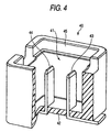
- Fig. 4 shows one known conventional fuse cavity of an electric connection box in which an automotive fuse is adapted to be mounted (see, for example, JP-A-2000-325875).
- This fuse cavity 40 includes a housing reception portion 41 having a tubular peripheral wall of a rectangular transverse cross-section, and a pair of tab terminals (serving as connection terminals) 43 and 44 project into the interior of the housing reception portion 41 through a bottom plate 42, and an upper end portion of the housing reception portion 41 is open, and serves as a fuse insertion port 45.
- the pair of tab terminals 43 and 44 are connected serially to a circuit within an electrical part mounted on a car body.
- Examples of automotive fuses each for mounting in the fuse cavity 40 include plug-in fuses shown respectively in Figs. 5 and 6.
- the plug-in fuse 50 shown in Fig. 5, is a long plug-in fuse, and comprises an insulating housing 57, and a fuse body 58 received and held in the insulating housing 57.
- the insulating housing 57 has a cover portion 52 attached to an upper end of a housing body portion 51 of a square tubular shape (having a square transverse cross-section) , and has a fitting opening portion 53 formed at a lower end of the housing body portion 51.
- the fuse body 58 includes a pair of tab-receiving terminals 54 and 55 for connection respectively to the tab terminals 43 and 44, and a fusible portion 56 integrally connected to the tab-receiving terminals 54 and 55 in overlying relation thereto.
- the cover portion 52 is locked to the housing body portion 51 by a pair of elastic lock piece portions (not shown).
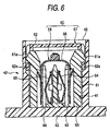
- the plug-in fuse 60 shown in Fig. 6, is a short plug-in fuse, and comprises an insulating housing 67, and a fuse body 68 received and held in the insulating housing 67.
- the insulating housing 67 has a cover portion 62 attached to an upper end of a housing body portion 61 of a square tubular shape (having a square transverse cross-section), and has a fitting opening portion 63 formed at a lower end of the housing body portion 61.
- the fuse body 68 includes a pair of tab-receiving terminals 64 and 65 for connection respectively to the tab terminals 43 and 44, and a fusible portion 66 integrally connected to the tab-receiving terminals 64 and 65 in overlying relation thereto.
- a pair of elastic lock piece portions 62a and 62a are formed respectively at lower ends of opposed side walls of the cover portion 62, and these lock piece portions 62a and 62a can be retainingly engaged respectively with a pair of retaining projections 61a and 61a formed on the housing body portion 61.
- Each of the plug-in fuses 50 and 60 is located in such a position that the fitting opening portion 53, 63 faces the fuse insertion port 45 in the fuse cavity 40, and then the housing body portion 51, 61 is inserted into the housing reception portion 41 until the fitting opening portion 53, 63 is brought into abutting engagement with the bottom plate 42, and by doing so, the tab-receiving terminals 54 and 55 (64 and 65) are electrically connected to the tab terminals 43 and 44, respectively.
- the fusible portion 56, 66 of the plug-in fuse 50, 60 melts to interrupt the circuit so that the large current, exceeding an allowable value, will not flow through the circuit, thereby protecting the circuit.
- the housing body portions 51 and 61 of the plug-in fuses 50 and 60 have the same transverse cross-sectional shape, and are different only in height from each other, while the housing reception portions 41 of the fuse cavities 40 of the electric connection box are different only in depth so that the fuse cavities can meet two kinds of (that is, long and short) plug-in fuses 50 and 60.
- two kinds of (long and short) plug-in fuses 50 and 60 can be suitably mounted merely by providing the housing reception portions 41 of different depths as described above.
- the short plug-in fuse 60 is erroneously fitted into the housing reception portion 41 for the long plug-in fuse 50, the top of the plug-in fuse 60 is completely received within the housing reception portion 41, and therefore there is a possibility that this fuse can not be withdrawn from the housing reception portion, for example, when exchanging the fuse.
- a plug-in fuse-mounting structure comprising:
- the short fuse cavity formed at the electric connection box, is somewhat different in the shape of an opening from a long fuse cavity since the short fuse cavity has the guide groove.
- the short and long fuse cavities are designed to have the same length and breadth (which are the basic dimensions of their transverse cross-sectional shape), so that these cavities maintain commonalities as fuse cavities, and therefore these fuse cavities never fail to be visually distinguished from the other cavities for other circuit elements (such as relay).
- the guide rib is formed on the outer side surface of the short plug-in fuse, while the guide groove is formed in the inner side surface of the short fuse cavity, and therefore even when the fuse is formed into a small size, it is easy to confirm its inserting direction when inserting it into the corresponding short fuse cavity, and the short plug-in fuse is prevented from being inserted in a wrong condition in which this fuse is turned 90 degrees.
- the short fuse cavity and the long fuse cavity are different from each other in transverse cross-sectional shape, and therefore the short fuse cavity and the long fuse cavity can be easily visually distinguished from each other even when the fuse is formed into a small size, and the efficiency of the fuse-mounting operation is enhanced.
- a pair of above-mentioned guide grooves are formed in each of opposed inner side surfaces of the short fuse cavity, and a pair of above-mentioned guide ribs are formed on each of opposite outer side surfaces of the short plug-in fuse corresponding respectively to the opposed inner side surfaces.
- recesses each formed between the corresponding pair of guide ribs, can serve as good positioning means when bringing a withdrawal jig into retaining engagement with the fuse, and this withdrawal jig can be guided into such a position that its axis coincides with the axis of the fuse, and therefore the withdrawal jig can be pulled up in a stable condition.
- Another aspect of the invention is directed to a electrical connection box comprising:
- Another aspect of the invention is directed to an erroneous fitting prevention method for plural kinds of plug-in fuses to fuse cavities, comprising:
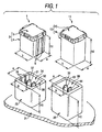
- Fig. 1 is a perspective view showing an important portion of one preferred embodiment of the plug-in fuse-mounting structure of the invention
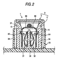
- Fig. 2 is a vertical cross-sectional view showing a condition in which a short plug-in fuse, shown in Fig. 1, is fitted in a short fuse cavity
- Fig. 3 is a vertical cross-sectional view showing a condition in which an attempt is made to fit the short plug-in fuse, shown in Fig. 1, into a long fuse cavity.
- each short plug-in fuse 1 and each long plug-in fuse 11 are inserted respectively into their corresponding short fuse cavity 23 and long fuse cavity 25 of an electric connection box 21, so that a fuse body 68, 58 of each of these fuses 1 and 11 is connected to tab terminals (connection terminals) 31 and 32 (43 and 44) projecting from a bottom portion 36 of the corresponding (short/long) fuse cavity 23, 25, as shown in Figs. 1 and 2.
- Each of the short and long plug-in fuses 1 and 11 has the fuse body 68, 58 incorporated in an insulating housing 3, 13.
- the insulating housings 3 and 13 include housing body portions 4 and 14 of a square tubular shape (having a square transverse cross-section), respectively, and covers 5 and 15 are attached respectively to upper ends of the housing body portions 4 and 14. As shown in Fig. 1, the housing body portions 4 and 14 have the same length a and breadth b (which are the basic dimensions of their transverse cross-sectional shape), but have different heights h1 and h2, respectively.
- a pair of guide ribs 6 and 6 are formed on a generally central portion of each of parallel opposite outer side surfaces of the housing body portion 4 of the short plug-in fuse 1, and extend in the direction of fitting of the fuse 1 into the fuse cavity 23. These guide ribs 6 are not formed on the housing body portion 14 of the long plug-in fuse 11.
- the fuse body 68 incorporated in the insulating housing 3 of the short plug-in fuse 1, is of an integral construction, and includes a pair of tab-receiving terminals 64 and 65 for connection respectively to the tab terminals 31 and 32 provided within a housing reception portion 34, and a fusible portion 66 interconnecting the tab-receiving terminals 64 and 65.
- This fuse body 68 is similar in construction to the fuse body 68 of the conventional short plug-in fuse 60 shown in Fig. 6.
- the fuse body incorporated in the insulating housing 13 of the long plug-in fuse 11, is similar in construction to the fuse body 58 of the conventional long plug-in fuse 50 shown in Fig. 5.
- the (short/long) fuse cavity 23, 25 includes the housing reception portion 34, 35 having a tubular peripheral wall of a rectangular transverse cross-section, and the pair of tab terminals 31 and 32 (43 and 44) project into the interior of the housing reception portion 34, 35 through the bottom plate 36, and the upper end portion of the housing reception portion 34, 35 is open, and serves as a fuse insertion port 37, 39.
- the pair of tab terminals 31 and 32 (43 and 44) are connected serially to a circuit within a corresponding electrical part mounted on a car body.
- the short fuse cavity 23 is set to a smaller fitting depth in corresponding relation to the short plug-in fuse 1, while the long fuse cavity 25 is set to a larger fitting depth in corresponding relation to the long plug-in fuse 11.
- the short fuse cavity 23 and the long fuse cavity 25 have the same length A and breadth B (which are frontage dimensions of the housing reception portion 34, 35), but have different height H1 and H2, respectively.
- a pair of guide grooves 38 and 38 are formed in each of opposed inner side surfaces of the housing reception portion 34 of the short fuse cavity 23, and extend in the direction of fitting of the short plug-in fuse 1 into this cavity 23, and each pair of guide ribs 6 on the short plug-in fuse 1 can be fitted respectively into the corresponding pair of guide grooves 38.
- the short plug-in fuse 1 is positively prevented from being erroneously inserted into the long fuse cavity 25.
- the short fuse cavity 23, formed at the electric connection box 21, is somewhat different in the shape of the opening from the long fuse cavity 25 since the short fuse cavity 23 has the guide grooves 38.
- the short and long fuse cavities 23 and 25 are designed to have the same length A and breadth B (which are the basic dimensions of their transverse cross-sectional shape), so that these cavities maintain commonalities as fuse cavities, and therefore these fuse cavities never fail to be visually distinguished from the other cavities for other circuit elements (such as relay).
- the guide ribs 6 are formed on the outer side surfaces of the short plug-in fuse 1, while the guide grooves 38 are formed in the inner side surfaces of the short fuse cavity 23, and therefore even when the fuse is formed into a small size, it is easy to confirm its inserting direction when inserting it into the corresponding short fuse cavity 23, and the short plug-in fuse 1 is prevented from being inserted in a wrong condition in which this fuse is turned 90 degrees.
- the guide ribs 6 are inserted respectively into the guide grooves 38, the guide ribs 6 are guided by the guide grooves 38, respectively, and therefore the gouging is prevented from developing during the insertion of the short plug-in fuse 1 into the short fuse cavity 23, and the smooth insertion of the fuse 1 is achieved.
- connection terminals 31 and 32 and the fuse body 68 within the short fuse cavity 23 will not be deformed, and the efficiency of the fuse-mounting operation is enhanced.
- the constructions of the guide grooves, guide rib and so on are not limited to those described in the above embodiment, and these portions can take various forms on the basis of the subject matter of the invention.
- the pair of guide ribs 6 and 6 are formed on each of the opposite outer side surfaces of the housing body portion 4 of the short plug-in fuse 1.
- the guide ribs 6 do not always need to be formed on these side surfaces, and the erroneous insertion prevention effect can be obtained when the guide ribs are formed on at least one side surface, and the number of the guide ribs may be arbitrary in so far as at least one guide rib is formed.
- recesses, each formed between the corresponding pair of guide ribs 6 and 6, can serve as good positioning means when bringing a withdrawal jig into retaining engagement with the fuse, and this withdrawal jig can be guided into such a position that its axis coincides with the axis of the fuse, and therefore the withdrawal jig can be pulled up in a stable condition.
- the short fuse cavity 23 and the long fuse cavity 25 are both provided on one electric connection box 21.
- the plug-in fuse-mounting structure of the invention is effective.
- the short fuse cavity formed at the electric connection box, is somewhat different in the shape of the opening from the long fuse cavity since the short fuse cavity has the guide grooves.
- the short and long fuse cavities are designed to have the same length and breadth (which are the basic dimensions of their transverse cross-sectional shape), so that these cavities maintain commonalities as fuse cavities, and therefore these fuse cavities never fail to be visually distinguished from the other cavities for other circuit elements (such as relay).
- the guide ribs are formed on the outer side surfaces of the short plug-in fuse, while the guide grooves are formed in the inner side surfaces of the short fuse cavity, and therefore even when the fuse is formed into a small size, it is easy to confirm its inserting direction when inserting it into the corresponding short fuse cavity, and the short plug-in fuse is prevented from being inserted in a wrong condition in which this fuse is turned 90 degrees.
- the short fuse cavity and the long fuse cavity are different from each other in transverse cross-sectional shape, and therefore the short fuse cavity and the long fuse cavity can be easily visually distinguished from each other even when the fuse is formed into a small size, and the efficiency of the fuse-mounting operation is enhanced.
Landscapes
- Fuses (AREA)
Abstract
A short plug-in fuse, having a fuse body received within
an insulating housing, is fitted into a short fuse cavity of
an electric connection box, so that the fuse body is connected
to tab terminals projecting from an inner bottom surface of
the fuse cavity. The short fuse cavity is set to a small fitting
depth in corresponding relation to the short plug-in fuse, and
a pair of guide grooves are formed in each of opposed inner
side surfaces of the short fuse cavity, and extend in a fitting
direction. A pair of guide ribs for respectively fitting into
the corresponding pair of guide grooves are formed on each of
parallel opposite outer side surfaces of the short plug-in
fuse.
Description
- This invention relates to a plug-in fuse-mounting structure, and more particularly to an improvement for preventing a short plug-in fuse from being erroneously fitted into a cavity for a long fuse.
- Fig. 4 shows one known conventional fuse cavity of an electric connection box in which an automotive fuse is adapted to be mounted (see, for example, JP-A-2000-325875).
- This
fuse cavity 40 includes ahousing reception portion 41 having a tubular peripheral wall of a rectangular transverse cross-section, and a pair of tab terminals (serving as connection terminals) 43 and 44 project into the interior of thehousing reception portion 41 through abottom plate 42, and an upper end portion of thehousing reception portion 41 is open, and serves as afuse insertion port 45. The pair oftab terminals - Examples of automotive fuses each for mounting in the
fuse cavity 40 include plug-in fuses shown respectively in Figs. 5 and 6. - The plug-in
fuse 50, shown in Fig. 5, is a long plug-in fuse, and comprises aninsulating housing 57, and afuse body 58 received and held in theinsulating housing 57. Theinsulating housing 57 has acover portion 52 attached to an upper end of ahousing body portion 51 of a square tubular shape (having a square transverse cross-section) , and has afitting opening portion 53 formed at a lower end of thehousing body portion 51. Thefuse body 58 includes a pair of tab-receiving terminals tab terminals fusible portion 56 integrally connected to the tab-receiving terminals cover portion 52 is locked to thehousing body portion 51 by a pair of elastic lock piece portions (not shown). - The plug-in
fuse 60, shown in Fig. 6, is a short plug-in fuse, and comprises aninsulating housing 67, and afuse body 68 received and held in theinsulating housing 67. Theinsulating housing 67 has acover portion 62 attached to an upper end of ahousing body portion 61 of a square tubular shape (having a square transverse cross-section), and has afitting opening portion 63 formed at a lower end of thehousing body portion 61. Thefuse body 68 includes a pair of tab-receiving terminals tab terminals fusible portion 66 integrally connected to the tab-receiving terminals - A pair of elastic
lock piece portions cover portion 62, and theselock piece portions retaining projections housing body portion 61. - Each of the plug-in
fuses fitting opening portion fuse insertion port 45 in thefuse cavity 40, and then thehousing body portion housing reception portion 41 until the fitting openingportion bottom plate 42, and by doing so, the tab-receivingterminals 54 and 55 (64 and 65) are electrically connected to thetab terminals - In the event that short-circuiting occurs, for example, in an electrical part such as a motor, so that a large current flows through an associated circuit, the
fusible portion fuse - Incidentally, in order that fuse cavities, provided at an electric connection box for an automobile, can be easily distinguished from the other cavities of this electric connection box for other circuit elements (such as relays) and that a fuse-mounting operation can be easily carried out, it is not desirable that many kinds of fuse cavities of different shapes and outer sizes are provided at the common electric connection box.
- Therefore, the
housing body portions fuses housing reception portions 41 of thefuse cavities 40 of the electric connection box are different only in depth so that the fuse cavities can meet two kinds of (that is, long and short) plug-infuses - Thus, two kinds of (long and short) plug-in
fuses housing reception portions 41 of different depths as described above. In this case, however, when the short plug-infuse 60 is erroneously fitted into thehousing reception portion 41 for the long plug-infuse 50, the top of the plug-infuse 60 is completely received within thehousing reception portion 41, and therefore there is a possibility that this fuse can not be withdrawn from the housing reception portion, for example, when exchanging the fuse. - Particularly with a recent high-density mounting design of electric connection boxes, there is a tendency for fuses to be formed into a smaller size, and when the difference in height between a long plug-in fuse and a short plug-in fuse becomes smaller, it becomes more difficult to visually distinguish between the short fuse cavity and the long fuse cavity since these conventional short and long fuse cavities have the same transverse cross-sectional shape, and this leads to a possibility that the erroneous fitting occurs more frequently.
- And besides, when the short plug-in fuse is formed into a small size, it becomes difficult to confirm its inserting direction when inserting it into the corresponding short fuse cavity, and there is a possibility that the short plug-in fuse is inserted in a wrong condition in which this fuse is turned 90 degrees, and as a result there is a fear that the connection terminals and the fuse body within the cavity are deformed.
- It is therefore an object of this invention to solve the above problems and more specifically to provide a good plug-in fuse-mounting structure which prevents a short plug-in fuse from being erroneously fitted into a cavity for a long fuse.
- The above object of the invention has been achieved by a plug-in fuse-mounting structure comprising:
- a plug-in fuse having an insulating housing and a fuse body received within the insulating housing; and
- a fuse cavity into which the plug-in fuse is fitted and which includes connection terminals projecting from an inner bottom surface thereof,
- wherein the fuse cavity has a small fitting depth in corresponding relation to a small height of the plug-in fuse, and at lease one guide groove is formed in an inner side surface of the fuse cavity so as to extend in a fitting direction of the plug-in fuse to the fuse cavity; and
- a guide rib fitting into the guide groove is formed on an outer side surface of the plug-in fuse.
-
- In the above construction, the short fuse cavity, formed at the electric connection box, is somewhat different in the shape of an opening from a long fuse cavity since the short fuse cavity has the guide groove. However, excepL the provision of the guide groove, the short and long fuse cavities are designed to have the same length and breadth (which are the basic dimensions of their transverse cross-sectional shape), so that these cavities maintain commonalities as fuse cavities, and therefore these fuse cavities never fail to be visually distinguished from the other cavities for other circuit elements (such as relay).
- Even if trying to insert the short plug-in fuse into the long fuse cavity by mistake, the short fuse can not be inserted into the long fuse cavity because of the interference of the guide rib, and therefore the short plug-in fuse is positively prevented from being erroneously fitted into the long fuse cavity.
- And besides, the guide rib is formed on the outer side surface of the short plug-in fuse, while the guide groove is formed in the inner side surface of the short fuse cavity, and therefore even when the fuse is formed into a small size, it is easy to confirm its inserting direction when inserting it into the corresponding short fuse cavity, and the short plug-in fuse is prevented from being inserted in a wrong condition in which this fuse is turned 90 degrees.
- Furthermore, the short fuse cavity and the long fuse cavity are different from each other in transverse cross-sectional shape, and therefore the short fuse cavity and the long fuse cavity can be easily visually distinguished from each other even when the fuse is formed into a small size, and the efficiency of the fuse-mounting operation is enhanced.
- Preferably, a pair of above-mentioned guide grooves are formed in each of opposed inner side surfaces of the short fuse cavity, and a pair of above-mentioned guide ribs are formed on each of opposite outer side surfaces of the short plug-in fuse corresponding respectively to the opposed inner side surfaces.
- In this case, recesses, each formed between the corresponding pair of guide ribs, can serve as good positioning means when bringing a withdrawal jig into retaining engagement with the fuse, and this withdrawal jig can be guided into such a position that its axis coincides with the axis of the fuse, and therefore the withdrawal jig can be pulled up in a stable condition.
- Another aspect of the invention is directed to a electrical connection box comprising:
- a first plug-in fuse and a second plug-in fuse, wherein a height of the first plug-in fuse is smaller than a height of the second fuse and each of the first plug-in fuse and the second plug-in fuse has a common basic outer shape; and
- a first fuse cavity and a second fuse cavity, wherein a depth of the first fuse cavity corresponds to the height of the first plug-in fuse and a depth of the second fuse cavity corresponds to the second plug-in fuse each of the first fuse cavity and the second fuse cavity has a basic cross-section; wherein the fuse cavity has at lease one guide groove extends in a fitting direction of the plug-in fuse to the fuse cavity, and the first plug-in fuse has at least one guide rib for fitting into the guide groove.
-
- By the above construction, plural kinds of plug-in fuses can be mounted reliably to the corresponding fuse cavities without erroneous fitting in the electric connection box.
- Another aspect of the invention is directed to an erroneous fitting prevention method for plural kinds of plug-in fuses to fuse cavities, comprising:
- providing a first plug-in fuse and a second plug-in fuse, wherein a height of the first plug-in fuse is smaller than a height of the second fuse and each of the first plug-in fuse and the second plug-in fuse has a common basic outer shape;
- providing a first fuse cavity and a second fuse cavity, wherein a depth of the first fuse cavity corresponds to the height of the first plug-in fuse and a depth of the second fuse cavity corresponds to the second plug-in fuse each of the first fuse cavity and the second fuse cavity has a basic cross-section; and
- fitting the first plug-in fuse into the first cavity; wherein the first fuse cavity has at lease one guide groove extends in a fitting direction of the plug-in fuse to the fuse cavity, and the first plug-in fuse has at least one guide rib for fitting into the guide groove, so that the first plug-in fuse is selectively fitted by the first fuse cavity and while the first plug-in fuse is not allowed to be fitted into the second fuse cavity.
-
- By providing a guide rib on a plug-in fuse having a short height, it is possible to prevent the short plug-in fuse from inserted into wrong fuse cavity for longer plug-in fuses. Therefore, the problem that this fuse can not be withdrawn from the housing reception portion can be solved.
-
- Fig. 1 is a perspective view showing an important portion of one preferred embodiment of a plug-in fuse-mounting structure of the invention;
- Fig. 2 is a vertical cross-sectional view showing a condition in which a short plug-in fuse, shown in Fig. 1, is fitted in a short fuse cavity;
- Fig. 3 is a vertical cross-sectional view showing a condition in which an attempt is made to fit the short plug-in fuse, shown in Fig. 1, into a long fuse cavity;
- Fig. 4 is a partly-broken, perspective view of a fuse cavity portion of a conventional electric connection box in which a plug-in fuse is adapted to be mounted;
- Fig. 5 is a cross-sectional view showing a condition in which a long plug-in fuse is mounted in the fuse cavity shown in Fig. 4; and
- Fig. 6 is a cross-sectional view showing a condition in which a short plug-in fuse is mounted in the fuse cavity shown in Fig. 4.
-
- One preferred embodiment of a plug-in fuse-mounting structure of the present invention will now be described in detail with reference to the accompanying drawings.
- Fig. 1 is a perspective view showing an important portion of one preferred embodiment of the plug-in fuse-mounting structure of the invention, Fig. 2 is a vertical cross-sectional view showing a condition in which a short plug-in fuse, shown in Fig. 1, is fitted in a short fuse cavity, and Fig. 3 is a vertical cross-sectional view showing a condition in which an attempt is made to fit the short plug-in fuse, shown in Fig. 1, into a long fuse cavity.
- In the plug-in fuse-mounting structure of this embodiment, each short plug-in
fuse 1 and each long plug-infuse 11 are inserted respectively into their correspondingshort fuse cavity 23 andlong fuse cavity 25 of anelectric connection box 21, so that afuse body fuses bottom portion 36 of the corresponding (short/long)fuse cavity - Each of the short and long plug-in
fuses fuse body insulating housing - The
insulating housings covers - A pair of
guide ribs fuse 1, and extend in the direction of fitting of thefuse 1 into thefuse cavity 23. Theseguide ribs 6 are not formed on the housing body portion 14 of the long plug-infuse 11. - The
fuse body 68, incorporated in the insulatinghousing 3 of the short plug-infuse 1, is of an integral construction, and includes a pair of tab-receivingterminals tab terminals housing reception portion 34, and afusible portion 66 interconnecting the tab-receivingterminals fuse body 68 is similar in construction to thefuse body 68 of the conventional short plug-infuse 60 shown in Fig. 6. - Although not shown in the drawings, the fuse body, incorporated in the insulating
housing 13 of the long plug-infuse 11, is similar in construction to thefuse body 58 of the conventional long plug-infuse 50 shown in Fig. 5. - The (short/long)
fuse cavity housing reception portion tab terminals 31 and 32 (43 and 44) project into the interior of thehousing reception portion bottom plate 36, and the upper end portion of thehousing reception portion fuse insertion port tab terminals 31 and 32 (43 and 44) are connected serially to a circuit within a corresponding electrical part mounted on a car body. - The
short fuse cavity 23 is set to a smaller fitting depth in corresponding relation to the short plug-infuse 1, while thelong fuse cavity 25 is set to a larger fitting depth in corresponding relation to the long plug-infuse 11. - As shown in Fig. 1, the
short fuse cavity 23 and thelong fuse cavity 25 have the same length A and breadth B (which are frontage dimensions of thehousing reception portion 34, 35), but have different height H1 and H2, respectively. - A pair of
guide grooves housing reception portion 34 of theshort fuse cavity 23, and extend in the direction of fitting of the short plug-infuse 1 into thiscavity 23, and each pair ofguide ribs 6 on the short plug-infuse 1 can be fitted respectively into the corresponding pair ofguide grooves 38. - These guide
grooves 38 are not formed in thehousing reception portion 35 of thelong fuse cavity 35. - Therefore, even if trying to insert the short plug-in
fuse 1 into thelong fuse cavity 25 by mistake, theguide ribs 6 interfere with thefuse insertion port 39, so that thefuse 1 can not be inserted into thehousing reception portion 35. - Therefore, the short plug-in
fuse 1 is positively prevented from being erroneously inserted into thelong fuse cavity 25. - Namely, in the plug-in fuse-mounting structure of this embodiment, the
short fuse cavity 23, formed at theelectric connection box 21, is somewhat different in the shape of the opening from thelong fuse cavity 25 since theshort fuse cavity 23 has theguide grooves 38. However, except the provision of theguide grooves 38, the short andlong fuse cavities - Even if trying to insert the short plug-in
fuse 1 into thelong fuse cavity 25 by mistake, thefuse 1 can not be inserted into thelong fuse cavity 25 because of the interference of theguide ribs 6, and therefore the short plug-infuse 1 is positively prevented from being erroneously fitted into thelong fuse cavity 25. - Therefore, there will not be encountered a situation in which the short plug-in
fuse 1 is erroneously fitted into thelong fuse cavity 25, so that the top of thisfuse 1 is completely received within thehousing reception portion 35, and therefore there is no fear that this fuse can not be withdrawn from the housing reception portion, for example, when exchanging the fuse. - And besides, the
guide ribs 6 are formed on the outer side surfaces of the short plug-infuse 1, while theguide grooves 38 are formed in the inner side surfaces of theshort fuse cavity 23, and therefore even when the fuse is formed into a small size, it is easy to confirm its inserting direction when inserting it into the correspondingshort fuse cavity 23, and the short plug-infuse 1 is prevented from being inserted in a wrong condition in which this fuse is turned 90 degrees. - Furthermore, when the
guide ribs 6 are inserted respectively into theguide grooves 38, theguide ribs 6 are guided by theguide grooves 38, respectively, and therefore the gouging is prevented from developing during the insertion of the short plug-infuse 1 into theshort fuse cavity 23, and the smooth insertion of thefuse 1 is achieved. - Therefore, the
connection terminals fuse body 68 within theshort fuse cavity 23 will not be deformed, and the efficiency of the fuse-mounting operation is enhanced. - In the plug-in fuse-mounting structure of the invention, the constructions of the guide grooves, guide rib and so on are not limited to those described in the above embodiment, and these portions can take various forms on the basis of the subject matter of the invention.
- For example, in the above embodiment, the pair of
guide ribs fuse 1. However, theguide ribs 6 do not always need to be formed on these side surfaces, and the erroneous insertion prevention effect can be obtained when the guide ribs are formed on at least one side surface, and the number of the guide ribs may be arbitrary in so far as at least one guide rib is formed. - However, in the case of the above embodiment in which the pair of
guide ribs guide ribs - In the above embodiment, for convenience' sake, the
short fuse cavity 23 and thelong fuse cavity 25 are both provided on oneelectric connection box 21. However, even in the case of an electric connection box in which one type of fuse cavities are provided according to the kind of car on which the electric connection box is to be mounted, there is a possibility that a short plug-in fuse which is an off-specification product is erroneously inserted into a long fuse cavity, for example, during the maintenance. Even in such a case, the plug-in fuse-mounting structure of the invention is effective. - As described above, in the plug-in fuse-mounting structure of the present invention, the short fuse cavity, formed at the electric connection box, is somewhat different in the shape of the opening from the long fuse cavity since the short fuse cavity has the guide grooves. However, except the provision of the guide grooves, the short and long fuse cavities are designed to have the same length and breadth (which are the basic dimensions of their transverse cross-sectional shape), so that these cavities maintain commonalities as fuse cavities, and therefore these fuse cavities never fail to be visually distinguished from the other cavities for other circuit elements (such as relay).
- Even if trying to insert the short plug-in fuse into the long fuse cavity by mistake, the short fuse can not be inserted into the long fuse cavity because of the interference of the guide ribs, and therefore the short plug-in fuse is positively prevented from being erroneously fitted into the long fuse cavity.
- And besides, the guide ribs are formed on the outer side surfaces of the short plug-in fuse, while the guide grooves are formed in the inner side surfaces of the short fuse cavity, and therefore even when the fuse is formed into a small size, it is easy to confirm its inserting direction when inserting it into the corresponding short fuse cavity, and the short plug-in fuse is prevented from being inserted in a wrong condition in which this fuse is turned 90 degrees.
- Furthermore, the short fuse cavity and the long fuse cavity are different from each other in transverse cross-sectional shape, and therefore the short fuse cavity and the long fuse cavity can be easily visually distinguished from each other even when the fuse is formed into a small size, and the efficiency of the fuse-mounting operation is enhanced.
Claims (4)
- A plug-in fuse-mounting structure comprising:a plug-in fuse having an insulating housing and a fuse body received within the insulating housing; anda fuse cavity into which said plug-in fuse is fitted and which includes connection terminals projecting from an inner bottom surface thereof,wherein said fuse cavity has a small fitting depth in corresponding relation to a small height of said plug-in fuse, and at lease one guide groove is formed in an inner side surface of said fuse cavity so as to extend in a fitting direction of said plug-in fuse to said fuse cavity; anda guide rib fitting into said guide groove is formed on an outer side surface of said plug-in fuse.
- A plug-in fuse-mounting structure according to claim 1, in which a pair of said guide grooves are formed in each of opposed inner side surfaces of said fuse cavity, and a pair of said guide ribs are formed on each of opposite outer side surfaces of said plug-in fuse corresponding respectively to said opposed inner side surfaces.
- A electrical connection box comprising:wherein said fuse cavity has at lease one guide groove extends in a fitting direction of said plug-in fuse to said fuse cavity, and said first plug-in fuse has at least one guide rib for fitting into said guide groove.a first plug-in fuse and a second plug-in fuse, wherein a height of the first plug-in fuse is smaller than a height of the second fuse and each of said first plug-in fuse and said second plug-in fuse has a common basic outer shape; anda first fuse cavity and a second fuse cavity, wherein a depth of the first fuse cavity corresponds to the height of the first plug-in fuse and a depth of the second fuse cavity corresponds to the second plug-in fuse each of said first fuse cavity and said second fuse cavity has a basic cross-section;
- An erroneous fitting prevention method for plural kinds of plug-in fuses to fuse cavities, comprising:wherein said first fuse cavity has at lease one guide groove extends in a fitting direction of said plug-in fuse to said fuse cavity, and said first plug-in fuse has at least one guide rib for fitting into said guide groove, so that said first plug-in fuse is selectively fitted by said first fuse cavity and while said first plug-in fuse is not allowed to be fitted into said second fuse cavity.providing a first plug-in fuse and a second plug-in fuse, wherein a height of the first plug-in fuse is smaller than a height of the second fuse and each of said first plug-in fuse and said second plug-in fuse has a common basic outer shape;providing a first fuse cavity and a second fuse cavity, wherein a depth of the first fuse cavity corresponds to the height of the first plug-in fuse and a depth of the second fuse cavity corresponds to the second plug-in fuse each of said first fuse cavity and said second fuse cavity has a basic cross-section; andfitting said first plug-in fuse into said first cavity;
Applications Claiming Priority (2)
| Application Number | Priority Date | Filing Date | Title |
|---|---|---|---|
| JP2003080425 | 2003-03-24 | ||
| JP2003080425A JP2004288518A (en) | 2003-03-24 | 2003-03-24 | Mounting structure of plug-in type fuse |
Publications (1)
| Publication Number | Publication Date |
|---|---|
| EP1463161A1 true EP1463161A1 (en) | 2004-09-29 |
Family
ID=32821424
Family Applications (1)
| Application Number | Title | Priority Date | Filing Date |
|---|---|---|---|
| EP04101204A Withdrawn EP1463161A1 (en) | 2003-03-24 | 2004-03-24 | Plug-in fuse-mounting structure |
Country Status (3)
| Country | Link |
|---|---|
| US (1) | US20040192113A1 (en) |
| EP (1) | EP1463161A1 (en) |
| JP (1) | JP2004288518A (en) |
Families Citing this family (10)
| Publication number | Priority date | Publication date | Assignee | Title |
|---|---|---|---|---|
| JP4226362B2 (en) * | 2003-03-12 | 2009-02-18 | 矢崎総業株式会社 | fuse |
| JP4706613B2 (en) * | 2006-03-24 | 2011-06-22 | 住友電装株式会社 | Slow blow fuse fuse element, slow blow fuse and electrical junction box |
| JP5014012B2 (en) * | 2007-07-31 | 2012-08-29 | 矢崎総業株式会社 | Power circuit breaker |
| JP5258432B2 (en) * | 2008-07-28 | 2013-08-07 | 矢崎総業株式会社 | Fuse block |
| US20100060408A1 (en) * | 2008-09-09 | 2010-03-11 | Wen-Tsung Cheng | Fuse module with indicating capability |
| JP5695975B2 (en) * | 2011-05-26 | 2015-04-08 | 矢崎総業株式会社 | Fusible link mounting structure and electrical junction box |
| LT3269011T (en) * | 2015-03-12 | 2021-05-10 | Aees Inc. | Low profile terminal assembly |
| US10636606B1 (en) * | 2019-03-01 | 2020-04-28 | Sumitomo Wiring Systems, Ltd. | Fuse housing assembly |
| US10916897B1 (en) | 2020-02-13 | 2021-02-09 | Aees Inc. | Battery mounted fuse holder |
| CN215377800U (en) * | 2021-07-21 | 2021-12-31 | 泰科电子(苏州)有限公司 | Terminal Protectors, Connectors and Connector Assemblies |
Citations (5)
| Publication number | Priority date | Publication date | Assignee | Title |
|---|---|---|---|---|
| US5629663A (en) * | 1993-07-02 | 1997-05-13 | Yazaki Corporation | Disconnection mechanism for a dark current fuse |
| US5883561A (en) * | 1995-11-24 | 1999-03-16 | Yazaki Corporation | Secondary short preventing mechanism of fuse |
| US5886612A (en) * | 1997-10-20 | 1999-03-23 | Littelfuse, Inc. | Female fuse housing |
| DE4447731C2 (en) * | 1994-11-19 | 1999-06-10 | Grote & Hartmann | Electrical plug-in connector unit for motor vehicle engine fuses |
| US20010043139A1 (en) * | 2000-05-18 | 2001-11-22 | Yazaki Corporation | Push-in type fuse |
Family Cites Families (3)
| Publication number | Priority date | Publication date | Assignee | Title |
|---|---|---|---|---|
| US5902155A (en) * | 1997-08-28 | 1999-05-11 | Molex Incorporated | Electrical connector assembly |
| JP2002289302A (en) * | 2001-03-27 | 2002-10-04 | Mitsumi Electric Co Ltd | Electrical connector |
| JP4047073B2 (en) * | 2002-05-31 | 2008-02-13 | 矢崎総業株式会社 | Electrical junction box cavity structure |
-
2003
- 2003-03-24 JP JP2003080425A patent/JP2004288518A/en active Pending
-
2004
- 2004-03-23 US US10/806,418 patent/US20040192113A1/en not_active Abandoned
- 2004-03-24 EP EP04101204A patent/EP1463161A1/en not_active Withdrawn
Patent Citations (5)
| Publication number | Priority date | Publication date | Assignee | Title |
|---|---|---|---|---|
| US5629663A (en) * | 1993-07-02 | 1997-05-13 | Yazaki Corporation | Disconnection mechanism for a dark current fuse |
| DE4447731C2 (en) * | 1994-11-19 | 1999-06-10 | Grote & Hartmann | Electrical plug-in connector unit for motor vehicle engine fuses |
| US5883561A (en) * | 1995-11-24 | 1999-03-16 | Yazaki Corporation | Secondary short preventing mechanism of fuse |
| US5886612A (en) * | 1997-10-20 | 1999-03-23 | Littelfuse, Inc. | Female fuse housing |
| US20010043139A1 (en) * | 2000-05-18 | 2001-11-22 | Yazaki Corporation | Push-in type fuse |
Also Published As
| Publication number | Publication date |
|---|---|
| US20040192113A1 (en) | 2004-09-30 |
| JP2004288518A (en) | 2004-10-14 |
Similar Documents
| Publication | Publication Date | Title |
|---|---|---|
| EP1873871B1 (en) | Electrical connector | |
| US7559808B2 (en) | Connector | |
| CN101359795B (en) | Power-circuit breaking device | |
| US6146200A (en) | Connector and a cap therefor | |
| CN100361356C (en) | Waterproof structure of electric junction box | |
| CN101218714B (en) | Connector Assemblies with Terminal Position Assurance Devices | |
| CN101136294B (en) | In-line fuse holder for female fuse | |
| EP0963008B1 (en) | A connector and a cap therefor | |
| EP0955696A1 (en) | Electrical connector with terminal position assurance device | |
| KR20170091732A (en) | Electric wire housing protector | |
| US20040192113A1 (en) | Plug-in fuse-mounting structure | |
| US6129574A (en) | Connector having a construction for preventing an erroneous assembling of a connector housing and a cover | |
| EP1641083B1 (en) | A connector and connector assembly | |
| JP2014054005A (en) | Electric connection box | |
| KR20170091151A (en) | Wire housing protector | |
| EP0427415A2 (en) | Sealed bulkhead connector for vehicles | |
| US7232342B2 (en) | Fuse cavity and electric junction box equipped therewith | |
| EP1014500A1 (en) | An electrical connection box and a method for manufacturing such an electrical connection box | |
| KR200318477Y1 (en) | Connector assembly for cars coupling as one body a number of pin | |
| JP4047073B2 (en) | Electrical junction box cavity structure | |
| US7355502B1 (en) | Direct relay connection to a fusible link | |
| JP3750347B2 (en) | Relay connector and electrical junction box provided with the relay connector | |
| JPH0850953A (en) | Structure to prevent incorrect insertion of connector terminals | |
| KR200318480Y1 (en) | A locking structure of a connector assembly for cars | |
| JP3995556B2 (en) | Electrical junction box cavity structure |
Legal Events
| Date | Code | Title | Description |
|---|---|---|---|
| PUAI | Public reference made under article 153(3) epc to a published international application that has entered the european phase |
Free format text: ORIGINAL CODE: 0009012 |
|
| AK | Designated contracting states |
Kind code of ref document: A1 Designated state(s): AT BE BG CH CY CZ DE DK EE ES FI FR GB GR HU IE IT LI LU MC NL PL PT RO SE SI SK TR |
|
| AX | Request for extension of the european patent |
Extension state: AL LT LV MK |
|
| 17P | Request for examination filed |
Effective date: 20050316 |
|
| AKX | Designation fees paid |
Designated state(s): DE FR GB IT |
|
| STAA | Information on the status of an ep patent application or granted ep patent |
Free format text: STATUS: THE APPLICATION IS DEEMED TO BE WITHDRAWN |
|
| 18D | Application deemed to be withdrawn |
Effective date: 20061001 |