EP1463142A2 - Controlled ventilation of fuel cell power plant - Google Patents
Controlled ventilation of fuel cell power plant Download PDFInfo
- Publication number
- EP1463142A2 EP1463142A2 EP04000511A EP04000511A EP1463142A2 EP 1463142 A2 EP1463142 A2 EP 1463142A2 EP 04000511 A EP04000511 A EP 04000511A EP 04000511 A EP04000511 A EP 04000511A EP 1463142 A2 EP1463142 A2 EP 1463142A2
- Authority
- EP
- European Patent Office
- Prior art keywords
- fuel cell
- flow rate
- cell stack
- fuel
- power plant
- Prior art date
- Legal status (The legal status is an assumption and is not a legal conclusion. Google has not performed a legal analysis and makes no representation as to the accuracy of the status listed.)
- Granted
Links
Images


Classifications
-
- H—ELECTRICITY
- H01—ELECTRIC ELEMENTS
- H01M—PROCESSES OR MEANS, e.g. BATTERIES, FOR THE DIRECT CONVERSION OF CHEMICAL ENERGY INTO ELECTRICAL ENERGY
- H01M8/00—Fuel cells; Manufacture thereof
- H01M8/04—Auxiliary arrangements, e.g. for control of pressure or for circulation of fluids
- H01M8/04298—Processes for controlling fuel cells or fuel cell systems
- H01M8/04313—Processes for controlling fuel cells or fuel cell systems characterised by the detection or assessment of variables; characterised by the detection or assessment of failure or abnormal function
- H01M8/04537—Electric variables
- H01M8/04604—Power, energy, capacity or load
- H01M8/04619—Power, energy, capacity or load of fuel cell stacks
-
- H—ELECTRICITY
- H01—ELECTRIC ELEMENTS
- H01M—PROCESSES OR MEANS, e.g. BATTERIES, FOR THE DIRECT CONVERSION OF CHEMICAL ENERGY INTO ELECTRICAL ENERGY
- H01M8/00—Fuel cells; Manufacture thereof
- H01M8/04—Auxiliary arrangements, e.g. for control of pressure or for circulation of fluids
- H01M8/04007—Auxiliary arrangements, e.g. for control of pressure or for circulation of fluids related to heat exchange
-
- H—ELECTRICITY
- H01—ELECTRIC ELEMENTS
- H01M—PROCESSES OR MEANS, e.g. BATTERIES, FOR THE DIRECT CONVERSION OF CHEMICAL ENERGY INTO ELECTRICAL ENERGY
- H01M8/00—Fuel cells; Manufacture thereof
- H01M8/04—Auxiliary arrangements, e.g. for control of pressure or for circulation of fluids
- H01M8/04082—Arrangements for control of reactant parameters, e.g. pressure or concentration
- H01M8/04089—Arrangements for control of reactant parameters, e.g. pressure or concentration of gaseous reactants
-
- H—ELECTRICITY
- H01—ELECTRIC ELEMENTS
- H01M—PROCESSES OR MEANS, e.g. BATTERIES, FOR THE DIRECT CONVERSION OF CHEMICAL ENERGY INTO ELECTRICAL ENERGY
- H01M8/00—Fuel cells; Manufacture thereof
- H01M8/04—Auxiliary arrangements, e.g. for control of pressure or for circulation of fluids
- H01M8/04298—Processes for controlling fuel cells or fuel cell systems
- H01M8/04694—Processes for controlling fuel cells or fuel cell systems characterised by variables to be controlled
- H01M8/04746—Pressure; Flow
- H01M8/04776—Pressure; Flow at auxiliary devices, e.g. reformer, compressor, burner
-
- H—ELECTRICITY
- H01—ELECTRIC ELEMENTS
- H01M—PROCESSES OR MEANS, e.g. BATTERIES, FOR THE DIRECT CONVERSION OF CHEMICAL ENERGY INTO ELECTRICAL ENERGY
- H01M8/00—Fuel cells; Manufacture thereof
- H01M8/24—Grouping of fuel cells, e.g. stacking of fuel cells
- H01M8/2465—Details of groupings of fuel cells
- H01M8/247—Arrangements for tightening a stack, for accommodation of a stack in a tank or for assembling different tanks
- H01M8/2475—Enclosures, casings or containers of fuel cell stacks
-
- H—ELECTRICITY
- H01—ELECTRIC ELEMENTS
- H01M—PROCESSES OR MEANS, e.g. BATTERIES, FOR THE DIRECT CONVERSION OF CHEMICAL ENERGY INTO ELECTRICAL ENERGY
- H01M8/00—Fuel cells; Manufacture thereof
- H01M8/04—Auxiliary arrangements, e.g. for control of pressure or for circulation of fluids
- H01M8/04082—Arrangements for control of reactant parameters, e.g. pressure or concentration
- H01M8/04201—Reactant storage and supply, e.g. means for feeding, pipes
- H01M8/04208—Cartridges, cryogenic media or cryogenic reservoirs
-
- H—ELECTRICITY
- H01—ELECTRIC ELEMENTS
- H01M—PROCESSES OR MEANS, e.g. BATTERIES, FOR THE DIRECT CONVERSION OF CHEMICAL ENERGY INTO ELECTRICAL ENERGY
- H01M8/00—Fuel cells; Manufacture thereof
- H01M8/04—Auxiliary arrangements, e.g. for control of pressure or for circulation of fluids
- H01M8/04298—Processes for controlling fuel cells or fuel cell systems
- H01M8/04313—Processes for controlling fuel cells or fuel cell systems characterised by the detection or assessment of variables; characterised by the detection or assessment of failure or abnormal function
- H01M8/0438—Pressure; Ambient pressure; Flow
- H01M8/04388—Pressure; Ambient pressure; Flow of anode reactants at the inlet or inside the fuel cell
-
- H—ELECTRICITY
- H01—ELECTRIC ELEMENTS
- H01M—PROCESSES OR MEANS, e.g. BATTERIES, FOR THE DIRECT CONVERSION OF CHEMICAL ENERGY INTO ELECTRICAL ENERGY
- H01M8/00—Fuel cells; Manufacture thereof
- H01M8/04—Auxiliary arrangements, e.g. for control of pressure or for circulation of fluids
- H01M8/04298—Processes for controlling fuel cells or fuel cell systems
- H01M8/04313—Processes for controlling fuel cells or fuel cell systems characterised by the detection or assessment of variables; characterised by the detection or assessment of failure or abnormal function
- H01M8/04537—Electric variables
- H01M8/04574—Current
- H01M8/04589—Current of fuel cell stacks
-
- Y—GENERAL TAGGING OF NEW TECHNOLOGICAL DEVELOPMENTS; GENERAL TAGGING OF CROSS-SECTIONAL TECHNOLOGIES SPANNING OVER SEVERAL SECTIONS OF THE IPC; TECHNICAL SUBJECTS COVERED BY FORMER USPC CROSS-REFERENCE ART COLLECTIONS [XRACs] AND DIGESTS
- Y02—TECHNOLOGIES OR APPLICATIONS FOR MITIGATION OR ADAPTATION AGAINST CLIMATE CHANGE
- Y02E—REDUCTION OF GREENHOUSE GAS [GHG] EMISSIONS, RELATED TO ENERGY GENERATION, TRANSMISSION OR DISTRIBUTION
- Y02E60/00—Enabling technologies; Technologies with a potential or indirect contribution to GHG emissions mitigation
- Y02E60/30—Hydrogen technology
- Y02E60/50—Fuel cells
Definitions
- This invention relates to ventilation of a casing which houses a fuel cell stack of a fuel cell power plant.
- the ventilator for sweeping out gas from the inside of the casing.
- the ventilator comprises an electric fan for ventilation installed in the casing, an open/close type door, a sensor for detecting an inflammable gas concentration in the casing and a controller.
- the controller increases the fan rotation speed to increase the ventilation air volume.
- the ventilator according to the prior art technique has a construction which responds to the concentration of inflammable gas in the casing, if the inflammable gas concentration in the casing rises rapidly, the ventilation air volume may be temporarily insufficient and the combustible gas concentration may exceed a permissible level. Thus, the ventilator must be increased in size in order to ensure that the ventilation air volume is sufficient.
- the prior art device detects the inflammable gas concentration by a sensor, but the inflammable gas concentration in the casing is not necessarily uniform, and the concentration distribution has a bias depending on the leak path of inflammable gas. Therefore, a discrepancy may arise between the inflammable gas concentration detected by the sensor, and the actual average concentration of inflammable gas in the casing, and this discrepancy becomes a factor which reduces the precision accuracy of the ventilation air volume.
- this invention provides a fuel cell power plant comprising a fuel cell stack comprising a laminate of fuel cells each of which comprises an anode a cathode and an electrolyte to generate power by an electrochemical reaction between a fuel gas supplied to the anode and an oxidant gas supplied to the cathode, via the electrolyte, a fuel gas supply device which supplies fuel gas to the anode, an oxidant gas supply device which supplies oxidant gas to the cathode, a casing which, among the fuel cell stack, the fuel gas supply device and the oxidant gas supply system, houses at least the fuel cell stack, a ventilator which ventilates the inside of the casing, and a controller programmed to control operation of the ventilator according to a power generation load of the fuel cell stack.
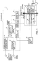
- FIG. 1 is a schematic diagram of a fuel cell power plant for a vehicle according to this invention.
- FIG. 2 is a block diagram describing a function of a target output calculating unit according to this invention.
- FIG. 3 is a block diagram describing a ventilation fan control function of the controller.
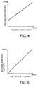
- FIG. 4 is a diagram describing the characteristics of a map of fuel gas leak flow rate stored by the controller.
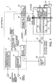
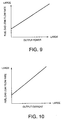
- FIG. 6 is a diagram describing the characteristics of a map of ventilation fan rotation speed stored by the controller.
- FIG. 7 is similar to FIG.1, but shows a second embodiment of this invention.
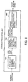
- FIG. 8 is a block diagram describing a ventilation fan control function of a controller according to the second embodiment of this invention.
- FIG. 12 is similar to FIG.1, but shows a third embodiment of this invention.
- FIG. 19 is a block diagram describing a ventilation fan control function of a controller according to the seventh embodiment of this invention.
- the fuel cell stack 2 is a laminate of fuel cells each of which comprises an anode 2a and cathode 2b on both sides of an electrolyte membrane 2c.
- the fuel cell stack 2 generates power according to an electrochemical reaction of the fuel gas supplied to the anode 2a and the oxidant gas supplied to the cathode 2b via the electrolyte membrane 2c.
- a programmable controller 10 controls the supply flow rates of fuel gas and oxidant gas according to the power generation output required of the fuel cell stack 2.
- the electric power generated by the fuel cell power plant 1 is supplied to an electric motor unit 30 for driving the vehicle.
- the electric motor unit 30 comprises an alternating current (AC) motor and an inverter, and converts the direct current supplied by the fuel cell power plant 1 into a predetermined alternating current to drive the AC motor.
- the operation of the AC motor is controlled according to a signal transmitted to the inverter from a controller 10.
- the rotation of the AC motor is transmitted to the vehicle drive wheels, and is used as power for running the vehicle.
- the controller 10 which performs control of the power generated by the fuel cell power plant 1, the drive force of the electric motor unit 30 via the inverter and the operation of the exhaust fan 7 of the casing 6, comprises a microcomputer provided with a central processing unit (CPU), read-only memory (ROM), random-access memory (RAM) and input/output interface (I/O interface).
- the controller may also comprise plural microcomputers.
- detection value signals are input to the controller 10 from a speed sensor 31 which detects a vehicle running speed, and an accelerator pedal depression sensor 32 which detects a depression amount of an accelerator pedal with which the vehicle is provided, respectively.
- the target output calculating unit 13 further calculates a target motor torque from the target drive force, the vehicle mass, the tire radius and the gear reduction ratio.
- the vehicle mass, tire radius and gear reduction ratio are all known values determined by the vehicle specification, if the target drive force is determined, the target motor torque can be uniquely computed.
- This embodiment also differs from the first embodiment in the details of the control of the exhaust gas flow rate of the exhaust fan 7 by the controller 10, i.e., the construction of the exhaust fan control unit 16.
- the exhaust gas flow rate of the exhaust fan 7 can be precisely controlled. Also in this embodiment, as in the first embodiment, a construction is possible wherein the anode effluent produced by the anode 2a after the power generation reaction is discharged into the casing 6.
- the fuel cell power plant 1 instead of the flow rate sensor 23 according to the third embodiment, is provided with a pressure sensor 24 which detects a pressure of the fuel tank 5, and a temperature sensor 27 which detects a temperature in the fuel tank 5.
- a pressure sensor 24 which detects a pressure of the fuel tank 5
- a temperature sensor 27 which detects a temperature in the fuel tank 5.
- the construction of the remaining hardware is identical to that of the third embodiment.
- the fuel gas leak flow rate estimating section 164 calculates the mass flow rate of fuel gas supplied to the fuel gas supply device 3 from the fuel tank 5, from the pressure and temperature in the fuel tank 5, by looking up a map having the characteristics shown in FIG. 14. Specifically, the variation of the fuel gas mass in the tank 5, i.e., the mass flow rate of fuel gas, is calculated from the pressure change.
- the control of the exhaust gas flow rate of the exhaust fan 7 after calculating the mass flow rate of fuel gas is identical to that of the third embodiment.
- the fuel cell stack 2 When the fuel cell stack 2 generates power, nitrogen permeates the anode 2a from the cathode 2b via the electrolyte 2c. When nitrogen enters the anode 2a, the power generating efficiency of the fuel cell stack 2 falls. Thus, the power generating efficiency is prevented from falling by occasionally purging anode effluent to the space in the casing 6.
- the fuel gas consumption flow rate calculating section 166 calculates the consumption flow rate of fuel gas which the fuel cell stack 2 consumes based on the output current of the fuel cell stack 2 detected by the current sensor 21. Herein, the consumption flow rate of fuel gas also increases, as the output current of the fuel cell stack 2 increases.
- FIGS. 18 and 19 a seventh embodiment of this invention will be described.
- the exhaust fan control unit 16 of the controller 10 is provided with an exhaust gas flow rate correction section 165 instead of the exhaust fan target rotation speed calculating section 163 of the first embodiment.
- the remaining construction is identical to that of the first embodiment.
- the deviation of the target exhaust gas flow rate and the real exhaust gas flow rate is calculated, and the command signal is corrected so that the deviation is reduced.
- the real exhaust gas flow rate of the exhaust fan 7 is definitively controlled to the target exhaust gas flow rate.
- the exhaust performance of the exhaust fan 7 may be affected by running wind.
- the exhaust gas flow rate of the exhaust fan 7 can be precisely controlled to the target exhaust gas flow rate by performing the above feedback correction of the command signal outputted to the exhaust fan 7.
- the feedback control of the exhaust gas flow rate described in this embodiment does not depend on the method of calculating the target exhaust gas flow rate. Therefore, the feedback control of the exhaust gas flow rate in this embodiment can be combined with any of the second to sixth embodiments.
Landscapes
- Life Sciences & Earth Sciences (AREA)
- Engineering & Computer Science (AREA)
- Manufacturing & Machinery (AREA)
- Sustainable Development (AREA)
- Sustainable Energy (AREA)
- Chemical & Material Sciences (AREA)
- Chemical Kinetics & Catalysis (AREA)
- Electrochemistry (AREA)
- General Chemical & Material Sciences (AREA)
- Fuel Cell (AREA)
- Ventilation (AREA)
- Air Conditioning Control Device (AREA)
Abstract
Description
n = number of moles of hydrogen in the tank,
R= gas constant,
V= tank volume, and
a, b = constants depending on the gas.
Claims (10)
- A fuel cell power plant (1) comprising:a fuel cell stack (2) comprising a laminate of fuel cells each of which comprises an anode (2a) a cathode (2b) and an electrolyte (2c) to generate power by an electrochemical reaction between a fuel gas supplied to the anode (2a) and an oxidant gas supplied to the cathode (2b), via the electrolyte (2c);a fuel gas supply device (3, 5, 5a) which supplies fuel gas to the anode (2a);an oxidant gas supply device (4) which supplies oxidant gas to the cathode (2b);a casing (6) which, among the fuel cell stack (2), the fuel gas supply device (3, 5, 5a) and the oxidant gas supply system (4), houses at least the fuel cell stack (2);a ventilator (7, 8) which ventilates the inside of the casing (6); anda controller (10) programmed to control operation of the ventilator (7, 8) according to a power generation load of the fuel cell stack (2).
- The fuel cell power plant (1) as defined in Claim 1, wherein the controller (10) is further programmed to control operation of the ventilator (7, 8) using a required power output of the fuel cell stack (2) as the load of the fuel cell stack (2).
- The fuel cell power plant (1) as defined in Claim 1, wherein the power plant (1) is a power plant for driving a vehicle, the vehicle comprises an accelerator pedal, the power plant (1) further comprises an accelerator pedal depression sensor (12) which detects a depression amount of the accelerator pedal and a vehicle speed sensor (11) which detects a vehicle running speed, and the controller (10) is further programmed to calculate the required power output of the fuel cell stack (2) based on the accelerator pedal depression amount and the vehicle running speed.
- The fuel cell power plant (1) as defined in Claim 1, wherein the power plant (1) further comprises a sensor (21, 22, 23, 24, 25, 27) which detects a running parameter of the power plant (1) corresponding to the power generation load of the fuel cell stack (2), and the controller 10 is further programmed to control the operation of the ventilator (7, 8) using the running parameter as the load of the fuel cell stack (2).
- The fuel cell power plant (1) as defined in Claim 4, wherein the running parameter detecting sensor (21, 22, 23, 24, 25, 27) comprises at least one of a sensor (21) which detects an output current of the fuel cell stack (2), and a sensor (22) which detects an output voltage of the fuel cell stack (2), and the controller (10) is further programmed to control the operation of the ventilator (7, 8) based on at least one of the output current of the fuel cell stack (2) and the output voltage of the fuel cell stack (2).
- The fuel cell power plant (1) as defined in Claim 4, wherein the running parameter detecting sensor (21, 22, 23, 24, 25, 27) comprises a sensor (23, 24, 27) which detects a fuel gas supply flow rate of fuel gas from the fuel gas supply device (3, 5, 5a) to the anode (2a), and the controller (10) is further programmed to control operation of the ventilator (7, 8) based on the fuel gas supply flow rate.
- The fuel cell power plant (1) as defined in Claim 6, wherein the fuel gas supply device (3, 5, 5a) comprises a tank (5) which stores fuel, the running parameter detecting sensor (21, 22, 23, 24, 25, 27) comprises a sensor (24) which detects a pressure in the tank (5), and the controller (10) is further programmed to calculate a pressure variation rate in the tank (5), and calculate the fuel gas supply flow rate based on the pressure variation rate.
- The fuel cell power plant (1) as defined in Claim 4, wherein the running parameter detecting sensor (21, 22, 23, 24, 25, 27) comprises a sensor (21) which detects an output current of the fuel cell stack (2), the power plant (1) further comprises a sensor (23) which detects a fuel gas supply flow rate to the anode (2a), and the controller (10) is further programmed to calculate a fuel gas consumption flow rate estimation value consumed by the fuel cell stack (2) from the output current of the fuel cell stack (2), and control the operation of the ventilator (7, 8) based on a difference of the fuel gas consumption flow rate estimation value and the fuel gas supply flow rate.
- The fuel cell power plant (1) as defined in any one of Claim 1 through Claim 8, wherein the power plant (1) further comprises a purging device (40, 41, 42) which purges gas which has accumulated in the anode (2a) to a space inside the casing (6) outside the fuel cell stack (2), and the controller (10) is further programmed to perform a correction of control of the operation of the ventilator (7, 8) according to an operating state of the purging device (40, 41, 42).
- The fuel cell power plant (1) as defined in any one of Claim 1 through Claim 9, wherein the power plant (1) further comprises a sensor (25) which detects a real ventilation flow rate of the casing (6), and the controller (10) is further programmed to set a target ventilation flow rate of the ventilator (7, 8) according to the power generation load of the fuel cell stack (2), and perform feedback control of the ventilator (7, 8) to cause the real ventilation flow rate to approach the target ventilation flow rate.
Applications Claiming Priority (2)
| Application Number | Priority Date | Filing Date | Title |
|---|---|---|---|
| JP2003042692 | 2003-02-20 | ||
| JP2003042692A JP4325216B2 (en) | 2003-02-20 | 2003-02-20 | Control device for fuel cell plant |
Publications (3)
| Publication Number | Publication Date |
|---|---|
| EP1463142A2 true EP1463142A2 (en) | 2004-09-29 |
| EP1463142A3 EP1463142A3 (en) | 2005-03-30 |
| EP1463142B1 EP1463142B1 (en) | 2008-06-18 |
Family
ID=32821102
Family Applications (1)
| Application Number | Title | Priority Date | Filing Date |
|---|---|---|---|
| EP04000511A Expired - Lifetime EP1463142B1 (en) | 2003-02-20 | 2004-01-13 | Controlled ventilation of fuel cell power plant |
Country Status (4)
| Country | Link |
|---|---|
| US (1) | US7285345B2 (en) |
| EP (1) | EP1463142B1 (en) |
| JP (1) | JP4325216B2 (en) |
| DE (1) | DE602004014433D1 (en) |
Cited By (2)
| Publication number | Priority date | Publication date | Assignee | Title |
|---|---|---|---|---|
| EP2212957A4 (en) * | 2007-10-22 | 2013-03-06 | Hydrogenics Corp | SUPPLY VENTILATION WITH COMPARTMENTS |
| DE102019128425A1 (en) * | 2019-10-22 | 2021-04-22 | Audi Ag | Method for operating a fuel cell device, fuel cell device and motor vehicle with a fuel cell device ' |
Families Citing this family (20)
| Publication number | Priority date | Publication date | Assignee | Title |
|---|---|---|---|---|
| US7829227B2 (en) * | 2003-04-04 | 2010-11-09 | Texaco Inc. | Integrated fuel processor apparatus and enclosure and methods of using same |
| JP2005203234A (en) * | 2004-01-15 | 2005-07-28 | Nissan Motor Co Ltd | Fuel cell seal deterioration determination apparatus and method |
| JP4889931B2 (en) * | 2004-08-30 | 2012-03-07 | 株式会社荏原製作所 | FUEL CELL UNIT AND METHOD OF OPERATING FUEL CELL UNIT |
| JP4972943B2 (en) * | 2006-01-31 | 2012-07-11 | 日産自動車株式会社 | Fuel cell system control apparatus and fuel cell system control method |
| JP5076472B2 (en) * | 2006-12-05 | 2012-11-21 | トヨタ自動車株式会社 | Fuel cell system |
| DE102008016578A1 (en) * | 2008-04-01 | 2009-10-08 | Daimler Ag | Fuel cell device and method for operating a fuel cell device |
| JP4893772B2 (en) * | 2009-03-31 | 2012-03-07 | トヨタ自動車株式会社 | Fuel cell system |
| JP5916707B2 (en) * | 2011-03-24 | 2016-05-11 | Jxエネルギー株式会社 | Fuel cell module |
| JP6318917B2 (en) * | 2014-06-30 | 2018-05-09 | アイシン精機株式会社 | Fuel cell system |
| JP6313139B2 (en) * | 2014-06-30 | 2018-04-18 | アイシン精機株式会社 | Fuel cell system |
| JP6385791B2 (en) * | 2014-10-22 | 2018-09-05 | トヨタホーム株式会社 | Air supply device |
| JP6554906B2 (en) * | 2015-05-20 | 2019-08-07 | スズキ株式会社 | Fuel cell system |
| JP7108848B2 (en) * | 2016-11-28 | 2022-07-29 | パナソニックIpマネジメント株式会社 | fuel cell system |
| KR102441064B1 (en) | 2017-07-17 | 2022-09-06 | 현대자동차주식회사 | Control method of fuel cell vehicle |
| CN111207459B (en) * | 2020-01-09 | 2021-12-07 | 青岛哈船道一科技有限公司 | Air optimizing device |
| CN111403777B (en) * | 2020-04-01 | 2022-04-22 | 广西玉柴机器股份有限公司 | Ventilation system of stack casing |
| JP7465172B2 (en) * | 2020-07-30 | 2024-04-10 | 株式会社東芝 | Fuel Cell Systems |
| KR102818172B1 (en) * | 2022-11-15 | 2025-06-10 | 주식회사 제이오텍 | Rechargeable battery safety cabinet with system to prevent and extinguish the fire |
| US20250005973A1 (en) * | 2023-06-29 | 2025-01-02 | Torc Robotics, Inc. | Systems and methods of detecting fluid release |
| US12546269B2 (en) | 2023-06-30 | 2026-02-10 | Torc Robotics, Inc. | Systems and methods of detecting fluid release |
Family Cites Families (10)
| Publication number | Priority date | Publication date | Assignee | Title |
|---|---|---|---|---|
| JPS58166670A (en) | 1982-03-27 | 1983-10-01 | Kansai Electric Power Co Inc:The | Fuel cell pressure control method |
| JP3138118B2 (en) | 1993-06-15 | 2001-02-26 | 大阪瓦斯株式会社 | Package type fuel cell power generator |
| JPH0831436A (en) * | 1994-07-13 | 1996-02-02 | Toshiba Corp | Packaged fuel cell power plant |
| JPH08167419A (en) | 1994-12-14 | 1996-06-25 | Toshiba Corp | Fuel cell power plant and its exhaust system |
| JP3739826B2 (en) | 1995-02-28 | 2006-01-25 | 三菱重工業株式会社 | Polymer electrolyte fuel cell system |
| JPH10116625A (en) | 1996-10-11 | 1998-05-06 | Nippon Telegr & Teleph Corp <Ntt> | Power supply system |
| JPH11111318A (en) | 1997-10-03 | 1999-04-23 | Sanyo Electric Co Ltd | Solid polymer fuel cell system |
| US6610431B1 (en) * | 2000-02-11 | 2003-08-26 | Plug Power Inc. | Method and apparatus for establishing a negative pressure inside an enclosure that houses a fuel cell system |
| JP2002056864A (en) * | 2000-08-10 | 2002-02-22 | Mitsubishi Heavy Ind Ltd | Fuel cell device and method of operating the same |
| JP5128032B2 (en) * | 2001-07-04 | 2013-01-23 | 本田技研工業株式会社 | Operation method of fuel cell |
-
2003
- 2003-02-20 JP JP2003042692A patent/JP4325216B2/en not_active Expired - Fee Related
-
2004
- 2004-01-13 EP EP04000511A patent/EP1463142B1/en not_active Expired - Lifetime
- 2004-01-13 DE DE602004014433T patent/DE602004014433D1/en not_active Expired - Lifetime
- 2004-01-14 US US10/756,254 patent/US7285345B2/en not_active Expired - Fee Related
Cited By (2)
| Publication number | Priority date | Publication date | Assignee | Title |
|---|---|---|---|---|
| EP2212957A4 (en) * | 2007-10-22 | 2013-03-06 | Hydrogenics Corp | SUPPLY VENTILATION WITH COMPARTMENTS |
| DE102019128425A1 (en) * | 2019-10-22 | 2021-04-22 | Audi Ag | Method for operating a fuel cell device, fuel cell device and motor vehicle with a fuel cell device ' |
Also Published As
| Publication number | Publication date |
|---|---|
| US20040166381A1 (en) | 2004-08-26 |
| JP4325216B2 (en) | 2009-09-02 |
| US7285345B2 (en) | 2007-10-23 |
| DE602004014433D1 (en) | 2008-07-31 |
| EP1463142B1 (en) | 2008-06-18 |
| JP2004253260A (en) | 2004-09-09 |
| EP1463142A3 (en) | 2005-03-30 |
Similar Documents
| Publication | Publication Date | Title |
|---|---|---|
| US7285345B2 (en) | Ventilation of fuel cell power plant | |
| US10249889B2 (en) | Fuel cell system | |
| US8541141B2 (en) | Fuel cell system | |
| JP4507584B2 (en) | Fuel cell system | |
| JP3572455B2 (en) | Fuel cell system | |
| US20100136451A1 (en) | Fuel cell system and current control method of same | |
| KR101006219B1 (en) | Fuel cell system | |
| US7318971B2 (en) | Fuel cell system utilizing control of operating current to adjust moisture content within fuel cell | |
| WO2005067088A2 (en) | Fuel cell system and control method thereof | |
| CN101292384A (en) | Fuel cell system, anode gas generation amount estimation device, and anode gas generation amount estimation method | |
| JP2003308868A (en) | Gas fuel supply device | |
| JP4185671B2 (en) | Control device for fuel cell system | |
| JP4686957B2 (en) | Fuel cell power generation control system | |
| US8148033B2 (en) | Fuel cell system with suppressed noise and vibration | |
| KR100845567B1 (en) | Fuel cell system, operation method thereof, and fuel cell vehicle | |
| JP3928526B2 (en) | Fuel cell system | |
| JP2005253270A (en) | Control device for fuel cell vehicle | |
| KR20190131726A (en) | Fuel cell system and method for controlling therof | |
| US20050118467A1 (en) | Fuel cell system and control method for fuel cell | |
| JP2005197156A (en) | Fuel cell system | |
| JP2006032205A (en) | Fuel cell system | |
| JP3698101B2 (en) | Control device for fuel reforming fuel cell system | |
| JP5070794B2 (en) | Fuel cell system | |
| JP2005044736A (en) | Control device for fuel cell system | |
| JP5210495B2 (en) | Fuel cell system |
Legal Events
| Date | Code | Title | Description |
|---|---|---|---|
| PUAI | Public reference made under article 153(3) epc to a published international application that has entered the european phase |
Free format text: ORIGINAL CODE: 0009012 |
|
| 17P | Request for examination filed |
Effective date: 20040113 |
|
| AK | Designated contracting states |
Kind code of ref document: A2 Designated state(s): AT BE BG CH CY CZ DE DK EE ES FI FR GB GR HU IE IT LI LU MC NL PT RO SE SI SK TR |
|
| AX | Request for extension of the european patent |
Extension state: AL LT LV MK |
|
| PUAL | Search report despatched |
Free format text: ORIGINAL CODE: 0009013 |
|
| AK | Designated contracting states |
Kind code of ref document: A3 Designated state(s): AT BE BG CH CY CZ DE DK EE ES FI FR GB GR HU IE IT LI LU MC NL PT RO SE SI SK TR |
|
| AX | Request for extension of the european patent |
Extension state: AL LT LV MK |
|
| 17Q | First examination report despatched |
Effective date: 20050602 |
|
| AKX | Designation fees paid |
Designated state(s): DE FR GB |
|
| 17Q | First examination report despatched |
Effective date: 20050602 |
|
| GRAP | Despatch of communication of intention to grant a patent |
Free format text: ORIGINAL CODE: EPIDOSNIGR1 |
|
| GRAS | Grant fee paid |
Free format text: ORIGINAL CODE: EPIDOSNIGR3 |
|
| GRAA | (expected) grant |
Free format text: ORIGINAL CODE: 0009210 |
|
| AK | Designated contracting states |
Kind code of ref document: B1 Designated state(s): DE FR GB |
|
| REG | Reference to a national code |
Ref country code: GB Ref legal event code: FG4D |
|
| REF | Corresponds to: |
Ref document number: 602004014433 Country of ref document: DE Date of ref document: 20080731 Kind code of ref document: P |
|
| PLBE | No opposition filed within time limit |
Free format text: ORIGINAL CODE: 0009261 |
|
| STAA | Information on the status of an ep patent application or granted ep patent |
Free format text: STATUS: NO OPPOSITION FILED WITHIN TIME LIMIT |
|
| 26N | No opposition filed |
Effective date: 20090319 |
|
| REG | Reference to a national code |
Ref country code: FR Ref legal event code: PLFP Year of fee payment: 13 |
|
| REG | Reference to a national code |
Ref country code: FR Ref legal event code: PLFP Year of fee payment: 14 |
|
| PGFP | Annual fee paid to national office [announced via postgrant information from national office to epo] |
Ref country code: FR Payment date: 20161215 Year of fee payment: 14 |
|
| PGFP | Annual fee paid to national office [announced via postgrant information from national office to epo] |
Ref country code: DE Payment date: 20170110 Year of fee payment: 14 |
|
| PGFP | Annual fee paid to national office [announced via postgrant information from national office to epo] |
Ref country code: GB Payment date: 20170111 Year of fee payment: 14 |
|
| REG | Reference to a national code |
Ref country code: DE Ref legal event code: R119 Ref document number: 602004014433 Country of ref document: DE |
|
| GBPC | Gb: european patent ceased through non-payment of renewal fee |
Effective date: 20180113 |
|
| PG25 | Lapsed in a contracting state [announced via postgrant information from national office to epo] |
Ref country code: FR Free format text: LAPSE BECAUSE OF NON-PAYMENT OF DUE FEES Effective date: 20180131 Ref country code: DE Free format text: LAPSE BECAUSE OF NON-PAYMENT OF DUE FEES Effective date: 20180801 |
|
| REG | Reference to a national code |
Ref country code: FR Ref legal event code: ST Effective date: 20180928 |
|
| PG25 | Lapsed in a contracting state [announced via postgrant information from national office to epo] |
Ref country code: GB Free format text: LAPSE BECAUSE OF NON-PAYMENT OF DUE FEES Effective date: 20180113 |