BACKGROUND OF THE INVENTION
1. Field of the Invention.
The present invention relates, in general, to the transfer of buffered data between
a host and a data storage device. Specifically, the invention relates to methods and
systems of extent-based cache memory management for the allocation of space in a data
buffer.
2. Relevant Background.
Data buffers may be used in data storage devices to facilitate the transfer of data
between a host (e.g., a computer) and the storage device (e.g., a disk drive). The buffers,
commonly constructed of Dynamic Random Access Memory (DRAM), provide a
temporary data storage location to buffer data transfers between the host and the storage
device.
The data space in a data buffer may be divided into one or more data segments.
Segmented data buffers are well-suited as a data speed-matching device to buffer data
between a host and a disk drive. However, when attempting to implement advanced
cache and disk algorithms that improve data access performance, buffer segments have
limitations.
One limitation is that buffer segments of fixed size often have a portion of their
space go unused. This space, which cannot be allocated for other data uses, adversely
impacts the storage density of the data buffer. Another limitation is that it is only
possible to track a single sequence of LBAs in a segmented buffer with conventional
methods of defining a Start LBA and using block counters to determine the length of the
LBA chain. This too limits the storage density of a buffer because LBA chains must be
stored in sequential segments in the buffer.
Still another limitation with conventional segmented buffers arises because data
segments are not transferred out of sequential order to and from the buffer. This is not
as much of a limitation for transfers from the host to the data buffer because host data is
almost always stored in chains of sequential LBAs. However, transfers of sequential
data segments between the buffer and a hard disk are often much less efficient because
sequential LBA data may be stored on different tracks of the disk. These and other
limitations of the conventional segmented data buffers are addressed by the present
invention.
SUMMARY OF THE INVENTION
An embodiment of the present invention includes an extent record for an extent
based data buffer which comprises a host pointer that links the extent record to a next
host extent record of a host extent record set, and a storage device pointer that links the
extent record to a next storage device extent record of a storage device extent record set.
Another embodiment of the invention includes a system for transferring data
between a host and a storage device which comprises a data buffer coupled to the host
and the storage device, wherein memory in the data buffer is divided into one or more
extents, an extent table associated with the data buffer, wherein the extent table
comprises at least one extent record, an LBA chain table coupled to the host and the
extent table, and a track section table coupled to the storage device and the extent table.
Still another embodiment of the invention includes a method of searching an
extent based data buffer which comprises searching a host pointer in an extent record to
find an LBA chain requested by a host, and searching a storage device pointer in the
extent record to find a track section requested by a storage device.
Additional novel features shall be set forth in part in the description that follows,
and in part will become apparent to those skilled in the art upon examination of the
following specification or may be learned by the practice of the invention. The features
and advantages of the invention may be realized and attained by means of the
instrumentalities, combinations, and methods particularly pointed out in the appended
claims.
BRIEF DESCRIPTION OF THE DRAWINGS
Fig. 1 shows a relationship between host LBAs and extents in the data buffer
according to an embodiment of the invention;
Fig. 2 shows a relationship between the storage device track sections and the
extents shown in Fig. 1;
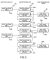
Fig. 3 shows a host and storage device independently traverses a set of extents
according to an embodiment of the invention;
Fig. 4 shows an example of the interaction between queued command data
structures according to an embodiment of the invention;
Fig. 5 shows an example of the interaction between non-queued command data
structures according to an embodiment of the invention;
Fig. 6 shows an embodiment of the system of the present invention;
Fig. 7 shows a flowchart of states for a disk pipe state machine according to an
embodiment of the invention;
Fig. 8 shows a flowchart of state for a host pipe state machine according to an
embodiment of the invention; and
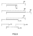
Fig. 9 shows examples of some types of cache hits.
DEFINITIONS
A buffer block is defined as 256 consecutive 16-bit words (or 512 consecutive 8-bit
bites) in the data buffer.
An extent is defined as a set of one or more sequential buffer blocks containing
data that is sequential in the logical block address (LBA) space. Extents represent
blocks received by host writes and disk reads without differentiation.
An extent table is defined as one or more extents linked together. This table
contains information about buffer block organization and how it relates to LBAs
contained in each buffer block. It also contains information about the order in which the
host and the disk traverse blocks in the buffer.
An LBA chain is defined as one or more extents linked together by the Extent
Allocation Table. An LBA chain contains data that is sequential in the logical block
address (LBA) space. The LBA chain size is the total size of its component extents.
The LBA chain table is defined as one or more LBA chains linked together by
the time order in which the LBA chain was created in the buffer. LBA chains may be
created by a disk read or by a host write. The LBA chain table is used by the host on
read commands to determine cache hit and miss conditions.
A track section is defined as one or more contiguous sectors on a single disk
track. This means a starting sector and a number of sectors. A track section is always
made up of one or more extents. A track section can never be smaller than an extent of
which it is made.
The track section table is defined as one or more track sections linked together to
describe the disk transfer of sectors on a singe disk track. The track section table defines
a track to the disk sequencer to be able to transfer track sections on the track without
stopping.
DETAILED DESCRIPTION OF THE PREFERRED EMBODIMENTS
The present invention includes a system and method of using a data buffer to
transfer data between a host and a storage device in response to read and write
commands. Space in the buffer memory is efficiently allocated by placing sequential
LBA data in sequential buffer blocks. However, as more commands are processed, the
buffer memory gets increasingly fragmented, making it difficult to allocate sequential
buffer space for new read and write requests while preserving previously cached data.
In the present invention, sequential LBAs of host data and storage data may be stored
non-sequentially in the data buffer. The non-sequential data in the buffer memory is
linked together for efficient searching and transfer by the host and the storage device.
Embodiments of the invention also include separate tables used by the host and
the storage medium for cataloging and searching the location of data in the buffer. Data
may be organized differently in a host than in a storage device and buffer performance
may be diminished when a single table is used by both to track data in the buffer. For
example, the host may be a computer with DRAM memory organized into sequential
LBAs while the storage device may be a hard disk drive with disk storage organized into
512 byte sectors that form tracks on the disk. In this case, the order in which blocks of
data are transferred the fastest between the host DRAM memory and the buffer can
differ from the order for the fastest transfers between the buffer and hard disk. By
having two separate tables, the host and the storage medium may search and transfer
buffer data in a sequence that is optimized for the way data is organized in these
components. Before describing embodiments of the system and method of the present
invention in more detail, some mechanisms of data transfers according to the present
invention will be examined.
Example of Buffered Data Transfer
In cache buffered data transfers categories of information are tracked for each
block of data in a data cache and these categories include: (1) The block location on the
disk, which identifies the data in a block that belongs to a specific LBA on the disk, (2)
the block location in the buffer, which identifies the data in a block that is transferred to
or from the disk via a specific location in the buffer, and (3) the block time coherency,
which identifies the relative time at which a block was received with respect to another
block pertaining to the same LBA and controls the block's validity. Generally, the
newest/youngest block containing a particular LBAs data is valid.
These categories of information are tied together by a method of cache
bookkeeping. One goal for bookkeeping of the cache information is to minimize the
hardware needed to describe the categories of information and tie them together. For
example, host and disk commands can vary in both the starting LBA and number of
blocks, while the data buffer is a fixed number of blocks. These commands may be
handled by assigning the exact number of buffer blocks that is required for each
command. As commands come in, the buffer blocks may be allocated and de-allocated
to the commands. In this way, the buffer block resources are used efficiently with
minimal wasting of space.
Referring now to Fig. 1, a relationship between host LBAs and extents in the
data buffer according to an embodiment of the invention is shown. Fig. 1 shows
interrelationships of host LBAs, buffer extents, and buffer blocks from the host's
perspective. The host provides two LBA chains 104 and 106 that are organized into
variable sized extents 102 in the data buffer. In this example, LBA chains 104 and 106
are divided into three extents each, labeled A, B, C and X, Y, Z, respectively. The
extents 102 may be linked anywhere in buffer, in any order, to form a host LBA chain.
Referring now to Fig. 2, a relationship is shown between the storage device track
sections and the extents shown in Fig. 1. This figure shows the interrelationships of disk
track sections, buffer extents, and buffer blocks from the storage device's point of view.
In this example, disk operations are broken down by the disk into tracks 204 and 206,
and further into track sections A, B, C and X, Y, Z, respectively. The track sections
from tracks 204 and 206 map to extents 202 in the buffer. In turn, the extents 202 map
back to the host LBA chains 104 and 106 and thus the host transfers.
On write operations, the order in which the write data was written by the host to
the buffer may be different than the order in which the data is written from the buffer to
the disk. This reordering may be due to disk positional optimization algorithms, or write
merging, or write cancellation. On read operations, the disk may append prefetched
data, or postfetched data (e.g., read lookahead) to the original host request. A disk track
section may be one or more extents in the buffer, and cannot be less than one extent.
When a track section is less than one extent, the disk may request that the extent either
be split, or trimmed to match the track section. As LBA chains filter down from the
host to the disk, the number of extents and their sizes may change to match the disk
track sections mapped to the LBA chains.
It is desirable to combine the host and storage device in a way that both may be
automated as much as possible. In looking at the different cases of host transfers and
storage transfers, and how they are related in the buffer, one can see that the buffer
extent lists shown can be the same, share common extents, or be completely different.
However, both lists are describing how a given client (host or storage device) will
navigate the buffer. The present invention includes a method and system where the lists
shown in Figs 1 and 2 may be combined into one list of buffer extents in which the
information pointing to the next extent for each client would be contained within the
extent. This creates a real-time relationship between the LBA chains and the track
sections.
Fig. 3 illustrates this by showing how a host and storage device may
independently traverse a set of extents 304 according to an embodiment of the present
invention. The host side 302 shows an LBA chain may comprise any number of extents
304. Meanwhile, on the disk side 306, the extents 304 making up an LBA chain may be
traversed in a different order within the LBA chain, or across LBA chains. This is due
to the physical boundaries of track sections. There is one list of buffer extents 304 in
which the information pointing to the next extent for the host and the storage device is
contained in each extent. This creates a real time relationship between the LBA chains
of the host and the track sections of the storage device.
Fig. 3 shows three LBA chain tables 302A, 302B and 302C traversing buffer
extents divided among the list of extents 304. The first LBA chain table 302A traverses
three extents 304A, B and C in sequential order. Meanwhile, the first disk track section
306A traverses the set of extents 304 in a different order that starts with extent 304B,
then goes to extent 304C, and finally jumps to extent 304A. Fig. 3 also shows that host
LBAs and disk tract sections can be split into different numbers of extents: Host LBA
chain table 302B traverses extent 304D and then extent 304E, while disk track section
306B only maps to extent 304D. Furthermore, Fig. 3 shows how host LBA chain table
302C maps to extents 304F, 304G, 304H and finally 304I, which are also extents
included in disk track section 306C and 306D.
The present invention includes a system and method of using a data buffer to
transfer data between a host and a storage device in response to read and write
commands. Space in the buffer memory is efficiently allocated by placing sequential
LBA data in sequential buffer blocks. However, as more commands are processed, the
buffer memory gets increasingly fragmented, making it difficult to allocate sequential
buffer space for new read and write requests while preserving previously cached data.
In the present invention, sequential LBAs of host data and storage data may be stored
non-sequentially in the data buffer. The non-sequential data in the buffer memory is
linked together for efficient searching and transfer by the host and the storage device.
Embodiments of the invention also include separate tables used by the host and
the storage medium for cataloging and searching the location of data in the buffer. Data
may be organized differently in a host than in a storage device and buffer performance
may be diminished when a single table is used by both to track data in the buffer. For
example, the host may be a computer with DRAM memory organized into sequential
LBAs while the storage device may be a hard disk drive with disk storage organized into
512 byte sectors that form tracks on the disk. In this case, the order in which blocks of
data are transferred the fastest between the host DRAM memory and the buffer can often
from the order for the fastest transfers between the buffer and hard disk. By having two
separate tables, the host and the storage medium may search and transfer buffer data in a
sequence that is optimized for the way data is organized in these components.
Example of Extented Cache Operation
Interface between the Host, the Cache, and the Disk
The Interface receives commands from the host and sends requests to the cache
for buffer resources. The cache may create new LBA chain table entries and allocate
buffer extents for the chain. The cache then sends a request to the disk. For a read, the
cache indicates what kind of speculative data to capture along with the request (this can
include pre-read, post-read, both or no data). The disk responds back to the cache with
information about the starting sector, and how many sectors it will read. The cache may
then modify the LBA chain entry and send status back to the interface.
Depending on implementation, the cache or host may start the cache search
engine, which will start the host transfer when data is available. For a write, the cache
may send a write request to the disk.
Read Command Processing
The interface receives a read command from the host, starting the cache search
engine. The cache search engine searches the LBA chain Table for hits. The cache
search engine may detect head hits and tail hits across one or more LBA chains. The
cache search engine initiates data transfers to the host for any cache hits. Each LBA
chain entry has a hit counter. This counter is initialized to zero when an LBA chain is
allocated and is incremented for each hit detected in that entry. When the hit counter
reaches its maximum count, it is not incremented any further.
If the cache search engine detects a cache miss (e.g., head, tail or full), it informs
the firmware of the starting miss LBA and the length of the miss. The interface
firmware requests a new LBA chain for the missing data from the cache firmware. This
request includes a starting LBA and a length. Also included in the request may be
information about speculative data such as pre-read, post-read or read the request only.
This may be based on the type of cache miss detected. Total misses may cause requests
for pre and post read, head hits cause requests for post-read and tail hits cause requests
for pre-read.
The cache firmware creates a new LBA chain entry from the first unused entry.
If free entries exist, the cache block finds the oldest LBA chain entry that the disk has
completed (e.g., data written to disk or read from disk). Extents associated with this
chain are released to the free pool. If the oldest LBA chain entry is a read, the firmware
may look at its associated hit counter to decide whether to free it.
The cache firmware allocates buffer space for this LBA chain by allocating free
extent(s). The amount of buffer space allocated depends on the Interface request (e.g.,
pre-request or post-request). If there is not enough free buffer space available or if there
are no free extents available, the cache firmware can wait for the disk to complete a
request/requests, free up extents associated with the completed request(s), and allocate
and link the newly freed buffer space to the new LBA chain. This process can be
repeated until enough resources have been freed up to fulfill the new request.
When the requisite resources are available, cache firmware may make a request
to the disk firmware to read the requested data. This includes a starting LBA, a length
and a starting extent number. The disk firmware creates a new Track queue entry that
includes the data from the cache request. The disk firmware then translates the LBA
into physical track, head and sector and calculates the landing sector. This information
may be fed back to the cache. The cache adjusts the starting LBA and length of the
LBA chain based on the first sector that can be read in before the request (pre-read) and
sets the Host Extent pointer to the extent/offset of the first host requested sector. The
host transfer may then be started, which may be controlled by the room logic. The disk
firmware then creates entries in its Track Section Queue, initiates a seek to the desired
track, sets the Disk Extent pointer, and starts the disk sequencer.
Write Command Processing
When the interface receives a write command from the host, the interface
firmware may request a new LBA chain for the write data from the cache firmware.
This request includes a starting LBA and a length.
The cache firmware may create a new LBA chain entry from the first unused
entry. If there are no unused entries, the cache firmware may then find the oldest LBA
chain entry that the disk has completed (data that has been written to disk or read from
disk). Extents associated with this chain are released to the free pool. If the oldest LBA
chain entry is a read, the firmware may look at its associated hit counter to decide
whether it should be freed.
The cache firmware may allocate buffer space for this LBA chain by allocating
free extent(s). If there is not enough free buffer space available or if there are no free
extents available, the cache firmware may wait for the disk to complete a
request/requests, free up extents associated with the completed request(s), and allocate
and link the newly freed buffer space to the new LBA chain. This process may be
repeated until enough resources have been freed up to fulfill the new request. At this
point the host transfer can be started, which may be controlled by the room logic.
If there is a time constraint from the host command until a transfer should be
started, the cache firmware should ensure that enough buffer resources are available to
transfer the first sector/block.
The cache firmware may then make a request to the disk firmware to write the
requested data. The data may include a starting LBA, a length, and a starting extent
number. The disk firmware may then create a new Track queue entry that includes the
data from the cache request. The disk firmware may then translate the LBA into a
physical track, head and sector and calculate the landing sector. The disk firmware may
then re-order its Track queue based on the physical location of the new request and
services it as it sees fit.
Cache Search Engine Operation
The cache search engine is a hardware state machine that when started, searches
valid LBA chain Table entries and detects cache hits of the requested data. The cache
search may be invoked by hardware at the receipt of a read command, or by firmware.
The cache search engine always searches from the youngest LBA chain to the
oldest. This ensures that any cache hit will be on the most recent data. The cache search
engine can detect hits on the head or tail of the requested data. If a head hit is detected,
that data is transferred to the host. If the cache search engine detects a cache miss (e.g.,
head, tail or full), it will indicate the starting miss LBA and the length of the miss. The
search engine will then stop and let the firmware start the read for the missing data. The
firmware can then start the search again, which will transfer the missing data to the host.
Disk Delayed Release Logic
There are two disk data pointers, a Real Time Pointer that increments for each
sector transferred to/from the disk and a Release Pointer that increments when the
sector(s) are determined as good. On a write, good means good servo status on the burst
just read. On a read, good means no ECC error or correction has fixed any errors.
Traversing the Track Section Table, then traversing the extents within the Track Section
Table, advances both pointers.
Example of Disk Command Queuing with Extented Cache
Disk Block Command Overview
The disk block receives commands for sets of LBAs from the Cache Manager
block. These commands tell the disk to transfer some set of sequential LBAs to or
from the buffer. It is the Disk block's responsibility to determine what physical
sectors on the disk need to be transferred to satisfy the given LBA request. Depending
on the disk layout, and the number and location of defective physical sectors, the
commands given to the Disk block may be processed into one or many track sections
on one or many tracks. Once a command is processed into its different tracks and track
sections, the Disk block works on an individual track. Once it finishes track sections for
a given track, it initiates a seek to the next track and begins to transfer requested track
sections on that track.
Disk Block Performance Issues
Since the Disk block works on one track at a time before seeking another
track, there are at least four factors that influence disk performance: (1) Data transfer
rate - How fast can the disk transfer data off the disk and into the buffer; (2) Seek time -
The time it takes to seek from one track to some other track; (3) Rotational latency - The
time the disk waits after arriving on a given track for the requested data to pass under the
head, and; (4) Command processing overhead - The time it takes for the disk to
recognize and process enough of a command to start transferring data associated with
that command. The disk data rate is a function of the read channel data rate, spin speed
and controller logic speed.
The seek time varies with the distance of the seek operation: The farther away
the target track is from the current track, the longer the seek time. Since the seek time is
often the largest portion of the time taken to execute a given command, it is
advantageous to be able to queue up track operations and execute them in the order that
minimizes their seek time. In other words, the next track is chosen to be the track that
has the smallest seek time from the current track.
Another factor for some track sections' access time is rotational latency.
Rotational latency is the difference between the first sector that can be transferred on a
given track after a seek, and the actual requested data. If the disk queues up track
section operations, it is useful to be able to choose the track section that is closest to the
anticipated arrival location on a given track.
Another factor for disk performance is the command processing time. This time
can be rather significant since the disk must do many calculations to translate a LBA
address into a physical disk address. In order to minimize the effect of this time the
disk firmware will try to do these calculations while a seek is taking place. This has
the effect of hiding the time it takes to make these calculations from the overall
command processing times. With command queuing, the disk executes these
calculations while other commands are transferring and/or while the disk is seeking
other tracks.
Disk Block Performance Goals
Since the time that the disk block takes to fully execute a given host command
makes up most of the time that the host has to wait for a given command, the disk
block's performance should be optimized. One goal is to maximize the amount of
time that the disk is actively transferring data to and from the buffer. This goal is
related to other sub-goals, including:
One sub-goal is to process as many commands as possible into Tracks and Track
sections. This gives the disk as much visibility as possible into the pending host
requests so that the next track to work on is selected based on efficiency. This also
allows the disk to maximize the amount of data that can be transferred on each track,
and allows the disk to be processing a new command while a previous one finishes.
Another sub-goal is to order the list of tracks based on shortest arrival time to the
requested data on that track. The next track to be selected should be based on how
quickly it can start transferring data to and from the disk.
Disk Command Types
The two types of data transfer commands that the disk receives, are read and
write commands. These two types of commands can be reorganized into two different
disk command types:
The first command type includes commands in which the whole command must
be completed from start to finish before starting other commands (e.g., read commands
and write commands with write caching off). This type of command requires the disk
to keep track of the progress of the command. When an error is encountered, the
status is given for the command (e.g., type of error, number of blocks done). If an
error occurs, sectors beyond the error do not have to be transferred. This type of
command is also referred to as "disk non-queued" command.
The second command type includes commands in which the command can be
processed and merged in with other existing commands and it can be processed in any
order (e.g., write commands with write caching on). This type of command may have
the disk keep track of blocks that are in error, but not which commands they came
from. When an error is encountered, status is given for the block in error (e.g., type of
error, block number of error). The disk attempts to transfer the sectors regardless of
errors contained within the command limits. This type of command is referred to as a
"disk queued" command.
Queued commands can be processed into tracks and track sections and then
ordered in a fashion that meets the performance goals discussed above. Non-queued
commands, however, take up the attention of the disk block until they are completed.
Thus, the goals described above are applied at the single command level for non-queued
commands. This means that it might be better to transfer the blocks in a
different order than the LBA order given by the command. In order to do this and
measure the progress of the command, the disk block should keep track of the track
sections in the order that they appear in the command.
Disk Block Command Queuing Structures
The first structure is the Disk Command Queue entry, which may be
represented as follows:
The Disk Command Queue holds entries that represent requests for disk
transfers. The Disk firmware uses these entries to keep track of command
information. If the command is a non-queued type then the command entry will exist
for the life of the Disk command. If the Disk command is a queued command, the Disk
firmware may free this structure, to handle a new command, after the command has
been processed into track and track sections. When servicing queued commands, the
Disk firmware posts errors with a block number designation.
The Disk Command Queue entry attributes may be described as follows:
For non-queued commands, the requirement to keep track of the commands
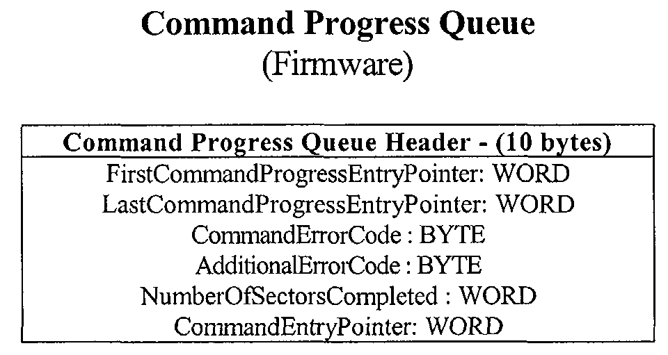
progress may be filled by the Command Progress Queue, which may be represented as
follows:
The Command Progress Queue may be used when the Disk firmware tracks the
status and progress of Disk commands on an individual basis. The header for the
Command Progress Queue keeps track of the error codes for a command as well as the
number of blocks completed. The Command Progress Queue attributes may be
described as follows:
There may be a Command Progress Queue entry for every track section
created for the command, which may be represented as follows:
When a command is processed, progress entries are queued for each track
section made in the order that they fall in the command (e.g., low LBA to high LBA).
When a track section is completed, the corresponding Progress Queue entry may be
removed and the entry pointed to by the previous pointer is updated. If the previous
pointer is NULL then the progress queue header is updated. The Command Progress
Queue Entry attributes may be described as follows:
For both queued and non-queued commands, the command queue entries may
be processed into a list of tracks to do and a list of track sections to do on a given
track. The Disk Track Queue is divided into a hardware section and a firmware
section. The hardware section is understood by the hardware so that it can choose, for
the firmware, the next track with the shortest access time. The firmware would then be
responsible for setting and maintaining the access time field based on the current track
position. The Hardware Track Queue may be represented as:
The Hardware Track Queue entry attributes may be described as follows:
The firmware section is used by the firmware to store additional information
about a given track. The firmware information describes information to transfer data on
the track. The Firmware Track Queue Entry may be represented by:
The Firmware Track Queue entry attributes may be described as follows:
Each track has a list of track sections to be completed on the track. The track
section entry provides the link to the buffer for the disk. The disk track section queue
is divided into two parts: a hardware part and a firmware part. The hardware part can be
used by the hardware to feed other disk hardware responsible for actually transferring
sectors off the disk. It contains information that can be used by the disk hardware to
transfer a set of contiguous sectors on a track. The Hardware Track Section Queue may
be represented by:
The Hardware Track Section Queue entry attributes may be described as
follows:
The second part of the disk track section is the firmware part. The firmware part
is used as an aid in manipulating and updating the hardware track section entries. It
contains information about how to traverse the hardware queue both forward and
backward. It may be used when the firmware needs to insert or delete entries in the
queue. The Firmware Track Section Queue may be represented by:
The Firmware Track Section Queue entry attributes may be described as
follows:
Disk Block Command Queuing Structure Interaction
As noted above, a disk can receive commands that are queued and non-queued.
For each case, the interaction between structures represented by the entries above may
be different.
Fig. 4 shows an example of the interaction between some of the above-described
structures in the case of a queued command. In this example, the Disk firmware
processes a given command into track queue entries 404 and track section queue entries
406. Since, in the queued mode, the Disk does not need to keep track of the transfer
progress on an individual command basis, the command entry 402 can be freed after the
command has been fully processed into it tracks and track sections. Therefore, in this
mode the Disk Command Queue 402 only needs to be two or three entries.
If the command status is not needed, then the command progress queue is also
not needed in this mode. Instead, errors for individual blocks or sets of blocks are
reported back to the client that sent the command. Other blocks can be assumed
transferred without error. In a queuing situation, it is desirable to be able to take in as
many commands as possible. This allows the disk firmware to see many tracks for reordering
and command merging and trimming. Therefore, it is also desirable to have
as many track queue entries 404 and track section queue entries 406 available as
possible.
Fig. 5 shows an example of the interaction between some of the above-described
structures in the case of a non-queued command. In the non-queued case, the disk
processes one command at a time from the Command Queue 502 and the command
status is tracked for each command. Since the disk processes one command at a
time, there is one Command Progress Queue 504 with entries for the track sections
from the Track Section Queue 506 for that command. In this mode, extra track
sections from an additional Track Section Queue 508 may be available so that the
sections can be queued up long before they are needed. Likewise, it may desirable to
have extra Command Progress Queue 504 entries.
When in non-queued mode, the Track Section Queues 506, 508 may be
smaller. Since the disk transfers on one track at a time, and there is a seek in between
transfers, there only needs to be enough track queue entries to keep the disk firmware
ahead of the transfer.
System Overview
Referring now to Fig. 6, an embodiment of the system of the present invention is
shown. In this embodiment, host data from a host 602 and storage data from a storage
device 604 (e.g., a hard disk drive) are transferred between each other through data
buffer 606. In response to read and write commands, data from host 602 is transferred
to and from the buffer 606 via a host pipe 618, and data from storage device 604 is
transferred to and from the buffer 606 via a storage pipe 620.
Data transfers between the host 602 and the buffer 606 are recorded in LBA
Chain Table 612 while data transfers between storage device 604 and the buffer 606 are
recorded in Track Section Table 614. As noted above, the host 602 can track data in
buffer 606 through the LBA Chain Table 612 and the storage device 604 can buffer data
through the Track Section Table 614.
The memory in the buffer 606 may be organized into one or more extents. Each
extent is of variable size, containing one or more sequential buffer block that includes
data sequential in the LBA space. When no extent is large enough to satisfy a new
request, multiple extents may be allocated for the request with the extents linked
together in sequential LBA order. The extent table 610 describes each extent and how
they are linked in buffer 606.
The buffer manager 608 uses the extent table 610 to control host pipe 618 and
disk pipe 620, and allows pipes 618 and 620 to transfer sequential host data 602 and
storage data 604 to and from non-sequential locations in buffer 606. The LBA chain
table 612 relates LBAs in host data 602 to buffer extents, and the track section table 614
relates disk tracks in the storage data 604 to the extents. The buffer manager 608 may
use LBA chain table 612 for cache hit detection 616.
Components of the system shown in Fig. 6 will now be described in more detail.
Extent Table
The extent table 610 shown in Fig. 6 (also referred to a an extent allocation
table) is an array of extent records that describes the user data buffer space. It allows
buffer block reordering and dynamic buffer block allocation.
Each extent record describes a single extent, and each buffer block is contained
in a single extent record. Every buffer block is mapped to an extent. Each extent record
describes the length and location of an extent of blocks in the DRAM buffer. An extent
record also describes how that buffer extent is linked to another buffer extent for both
the host and the disk transfers, making the extent allocation table independently
traversable for each type of transfer.
Extent records have links for traversing the extent allocation table as well as
flags. The flags describe host activity, disk activity, and data status within an extent.
Table 1 below describes an example extent record that supports up to 1024 extent
records, and a DRAM buffer of 64Mbits (16384 blocks).
| Example Extent Record |
| Extent Record |
| Extent Record Field | Number of Bits |
| StartingBufferBlock |
| | 14 bits |
| NextBufferExtent |
| | 10 bits |
| NextHostExtent |
| | 10 bits |
| NextDiskExtent |
| | 10 bits |
| Flags: |
| DiskActive | 1 bit |
| HostActive |
| | 1 bit |
| DataValid |
| | 1 bit |
| DataDirty |
| | 1 bit |
| Reserved | 1 bit |
| Reserved | 1 bit |
| Reserved | 1 bit |
| Reserved | 1 bit |
| TOTAL | 52 bits (6.5 bytes) |
The Extent Record fields may be described as follows:
The Flags may be described as follows:
LBA Chain Table
The LBA chain table is a time-ordered list of LBA chains in the buffer. Each
LBA chain table entry defines a stream of sequential LBAs spread across one or more
buffer extents. The extents that make up the chain are linked together by the extent
allocation table. A particular LBA may exist in more than one LBA chain and extent.
However, since the LBA chain table is linked in time order, the LBA in the most recent
chain (closest to the head) is the most valid. Table 2 below describes an example of an
LBA chain table entry that supports up to 1024 extent records, and up to 64 LBA chains.
| Example LBA Chain Table Entry |
| LBA Chain Entry |
| LBA Chain Field Name | Number of bits |
| StartingLBA | 32 bits |
| LBAChainLength | 16 bits |
| StartingExtent |
| | 10 bits |
| NextLBAChain |
| | 6 bits |
| PreviousLBAChain |
| | 6 bits |
| HitCounter |
| | 4 bits |
| Flags: |
| Locked | 1 bit |
| WriteData |
| | 1 bit |
| WriteCacheEnabled |
| | 1 bit |
| ScanActive |
| | 1 bit |
| DiskInUse |
| | 1 bit |
| Reserved | 1 bit |
| TOTAL | 80 bits (10 bytes) |
The LBA Chain Fields may be described as follows:
The Flags may be described as follows:
The Track Section Table
The track section table describes how to transfer a given track of data between
the disk formatter and the data buffer. A list of extents to be traversed in the buffer,
along with disk track information, tell the formatter how to transfer the extents in the
buffer with respect to a physical track on the disk. A disk track may be transferred using
one or more extents. Each disk track section is a contiguous number of sectors and
corresponds to at least one extent of blocks in the buffer. Table 3 shows an example of
a disk track section table entry:
| Example of a Track Section Entry |
| Track Section Entry |
| Field Name | Number Of Bits |
| StartingExtent |
| | 10 bits |
| StartingOffsetInExtent |
| | 14 bits |
| Flags |
| | 6 bits |
| StartingSector | 12 bits |
| EndingSector |
| | 12 bits |
| HardwareNextTrackSection |
| | 8 bits |
| FirmwareTrackSection |
| | 8 bits |
| Total | 70 bits (8.75 bytes) |
The field names may be defined as follows:
Disk Pipe
The disk pipe is the disk data transfer hardware that handles transfers
between the data buffer and the disk. This hardware may be incorporated into the disk
DRAM port. At a particular point in time, this block may be either reading or writing,
and one buffer pointer may be required. The components of the disk pipe include the
Disk Data Pointer, the
Disk Room Logic, and the
Disk Delayed Release Logic. Below is
list of the disk pipe registers that may be included in a disk pipe register set.
| Disk Pipe Registers | Register Type | Access |
| DiskPipeControl | Input | Read/Write |
| DiskPipeStatus | Output | Read only |
| TrackSectionNumber | Input | Read/Write |
| DiskTransferCount | Input | Read/Write |
| DiskBlockRemainingcount | Output | Read/Write |
| DiskRealTimeDataPointer | Output | Read/Write |
| DiskReleaseDataPointer | Output | Read/Write |
| ExtentBlockCount | Output | Read/Write |
| ExtentBlockRemainingCount | Output | Read/Write |
| ExtentBlockDoneCount | Output | Read only |
The
Disk Pipe Control Register may be described in the following table:
| Disk Pipe Control |
| Bit # | Bit Name | Bit Description |
| 0 | Start Transfer | Set to initiate a disk pipe transfer starting at the specified starting track section. |
| 1 | Disk Pipe Write | Set by firmware prior to disk pipe transfer to specify data direction from buffer to disk. |
| 2 | DiskPipeRead | Set by firmware prior to disk pipe transfer to specify data direction from disk to buffer |
| 3 | StopTransfer | Set by firmware to halt the disk pipe transfer |
The
Disk Pipe Status register includes a set of flags that may be used with the
disk data pointers to control the room logic and interact with the extent allocation table
entries.
| Disk Pipe Status |
| Bit # | Bit Name | Bit Description |
| 0 | Disk Pipe Active | This is a bit to indicate that the disk pipe is currently transferring data to/from the buffer. |
| 1 | Disk Write Active | This is a bit that indicates the disk pipe is set up for writing data from buffer to disk. |
| 2 | DiskReadActive | This is a bit that indicates the disk pipe is set up for reading data from disk to buffer. |
| 3 | DiskNoRoom | This is a bit to indicate whether or not the disk may continue data transfer in the current extent. |
The Track Section Number register is an input register to the disk pipe. This
register is set by the firmware prior to starting a disk pipe transfer. It is set to the starting
track section entry number on which the disk pipe is to operate. Contained within the
track section entry may be disk sequencer information about the extent to locate the data
in the buffer, and the disk track to locate the data on the disk.
The Disk Transfer Count register is an input register set by the firmware
before starting the transfer to the total number of disk sectors intended to transfer.
The Disk Block Remaining Count register is an output register that indicates
the number of blocks remaining for the disk pipe to transfer (according to the
Disk Real Time Data Pointer). The hardware may update this register after the
Disk Real Time Data Pointer completes the transfer of one sector to/from the disk.
The
Disk Real Time Data Pointer is the current position of the disk sequencer
in terms of the extent number and block offset within that extent. The real-time pointer
indicates the block on which the disk is currently working but may not have released.
An example of the real-time disk data pointer looks as follows:
| DiskRealTimeDataPointer (24 bits) |
| ExtentNumber | BlockOffsetIntoExtent | |
| 10 bits | 14 bits |
In this example the pointer is a three-byte field that describes the disk's
buffer address. The 10 bit extent number allows for as many as 1024 extents. The 14
bit offset allows for a 64Mbit buffer.
BufferBlockNumber = ExtentNumber→StartingBufferBlock + BlockOffsetIntoExtent BufferByteAddress = BufferBlockNumber* 512
When the disk data pointer is not actively being used to transfer data, the ExtentNumber
field may be set to NULL. This helps the extent logic distinguish between the disk pipe
transferring data in an extent versus sitting in an extent because it was the last one in a
chain.
The
DiskReleaseDataPointer indicates the block that is next to release by
the disk pipe in terms of the extent number and block offset within that extent. The
release pointer indicates the next block that is to be read or written successfully by the
disk pipe. If the
BlockOffsetIntoExtent is set to
zero, it means that no blocks have been
released in this extent. If the
BlockOffsetIntoExtent is set to
one, it means that the 0
th
block in the extent has been released. If the
BlockOffsetIntoExtent is set to
two, it means
that the 0
th block and the 1
st block in the extent have been released, and so on. An
example of the release disk data pointer looks as follows:
| DiskReleaseDataPointer (24 bits) |
| ExtentNumber | BlockOffsetIntoExtent | |
| 10 bits | 14 bits |
In this example, the pointer is a three-byte field that describes the disk's buffer address.
The 10 bit extent number allows for as many as 1024 extents. The 14 bit offset allows
for a 64Mbit buffer.
BufferBlockNumber = ExtentNumber→StartingBufferBlock + BlockOffsetlntoExtent BufferByteAddress = BufferBlockNumber * 512
When the disk data pointer is not actively being used to transfer data, the
ExtentNumber
field may be set to NULL. This helps the extent logic distinguish between the disk pipe
transferring data in an extent versus sitting in an extent because it was the last one in a
chain.
The ExtentBlockCount register is an output register from the disk pipe and
specifies the total number of blocks in the current extent as indicated by the
DiskRealTimeDataPointer. This value is computed by the hardware every time
DiskRealTimeDataPointer.ExtentNumber is set to a new extent.
ExtentBlockCount = Extent[NextDiskExtent].StartingBufferBlock - Extent[ExtentNumber].StartingBufferBlock
The ExtentBlockRemainingCount is an output register from the disk pipe
and it specifies the number of blocks remaining to transfer in the current extent as
indicated by the DiskRealTimeDataPointer. Upon entering an extent, the hardware
loads this register with ExtentBlockCount and then decrements it every time a disk data
sector pulse occurs. Since this count field is relevant to the disk real-time pointer, it
does not reflect blocks released to the host.
The ExtentBlockDoneCount register is an output register from the disk pipe
and it specifies the number of blocks released in the current extent as indicated by the
DiskRealTimeDataPointer. Upon entering an extent, the hardware loads this register
with zero and then increments it every time a disk data sector pulse occurs. Since this
count field is relevant to the disk real-time pointer it does not reflect blocks released to
the host.
Disk Pipe State Machine
State transitions may be caused by disk pipe input registers, signals from
other blocks, and disk pipe output register values. The example below lists some disk
pipe states and actions taken in each state. The
CurrentSectorNumber register may be
updated by the disk sequencer.
Fig. 7 is a disk pipe state machine flowchart that shows the order of the disk
pipe states from the list above. In this flowchart example, the disk pipe state machine is
in an idle state 702 until the initialize state 704 is activated and a transfer starts. Upon
start of a transfer, the machine enters the ConnectToTrackSection state 706 followed by
the FirstExtent state 708. Once the first extent has been identified in the FirstExtent
state 708, the machine enters a conditional state 710 that may be under the control of the
Disk Room Logic.
The Disk Room Logic uses the track section table (disk command queue),
the extent records, and the disk data pointer to enable or disable disk data transfers. The
Disk Room Logic may use the DiskRealTimeDataPointer to determine room.
Some scenarios presented to the disk room logic include: (1) DiskNoRoom
on a write command where the disk is about to start a write from an extent and that
extent has not yet been written with data from the host. In this scenario, the host and
disk are active in the same extent, both are writing, and the disk data pointer is greater or
equal to the host data pointer (i.e., the disk is about to pass the host in the same extent).
(2) DiskNoRoom on read commands is normally not encountered since all read data
originates from the disk, and there should be room on disk reads.
One example of a Boolean equation for DiskNoRoom is:
DiskNoRoom = DiskWriteActive & ((HostActive & HostWriteActive & (DiskRealTimeDataPointer.BlockOffset ≥ HostExtentOffset)) | (!HostActive & !DataValid))
Where HostActive and DataValid refer to the bits in the extent pointed to by the
DiskRealTimeDataPointer.ExtentNumber.
Referring back to Fig. 7, when the Disk Room Logic determines that the
DiskNoRoom condition is true, then the machine goes from the conditional state 710 to
the BlockNoRoom state 712. The machine may remain in the BlockNoRoom state 712
until the Disk Room Logic sets the DiskNoRoom condition to false and the machine
enters the SectorTransfer state 714. Alternatively, the BlockNoRoom state 712 may be
bypassed when the Disk Room Logic finds the DiskNoRoom condition false when the
machine first enters the conditional state 710. In this case, the machine passes directly
from the conditional state 710 to the SectorTransfer state 714.
Once the machine completes the sector transfer, it passes from the
SectorTransfer state 714 to the NextBlock state 716. In the NextBlock state 716 the
machine determines whether another extent should be transferred between the disk and
data buffer. If so, the machine enters the NextExtent state 718. Then the machine
determines whether the next extent is the final extent of the track section, and if so, it
enters the NextTrackSection state 720. In the NextTrackSection state 720 the machine
determines if there are anymore track sections to transfer and if not, it reenters and idle
state 722.
Disk Delayed Release Logic: The disk delayed release logic serves the
purpose of allowing the disk to transfer sectors to and from the buffer in real-time, but
delays the release of those sectors until validation by some later event. On read
commands, the ECC processing causes the release (or validation) of the sector at a point
in time later than the actual sector's data was transferred to the buffer. On write
commands, it is the next nearest servo burst that provides the release for the prior sectors
that are already in the buffer. In either case, it is necessary to have a real-time disk data
pointer that points to the buffer location at which the disk pipe is actually working.
Another disk data pointer will follow behind the real-time one to validate sectors in the
buffer via a delayed signal from the disk hardware. The two disk data pointers will be
called the Disk Release Data Pointer, and the Disk Real-time Data Pointer.
The Host Pipe
The host pipe is the host data transfer hardware that handles data transfers
between the host and the data buffer. This hardware may be incorporated into the host
DRAM port. At a given point in time, this block may be either reading or writing, and
one buffer pointer may be required. The host pipe describes the operation of the host
data transfer in relation to a specific extent and LBA chain. The host pipe operates in
one extent of an LBA chain at any time. Host pipe transfers may be started by the
firmware or by the hardware. On reads, cache hits are started automatically by the
hardware. On cache misses, the firmware starts the host read transfer. On writes, the
firmware starts the host transfer. The host pipe registers have ties into both the extent
records and the LBA chain table. The host pipe registers can be used at any time, by the
host, the cache, or the disk, to determine the current host activity in an LBA chain or an
extent. The example below lists host pipe registers that may be included in a host pipe
register set.
| Host Pipe Registers | Register Type | Access |
| HostPipeControl | Input | Read/Write |
| HostPipeStatus | Output | Read only |
| LBAChainNumber | Input | Read/Write |
| StartingLBAInChain | Input | Read/Write |
| LBAOffsetInChain | Output | Read only |
| LBACount | Input | Read/Write |
| LBARemainingCount | Output | Read/Write |
| LBADoneCount | Output | Read only |
| StartingExtent | Output | Read only |
| ExtentNumber | Output | Read only |
| ExtentOffset | Output | Read/Write |
| ExtentBlockCount | Output | Read/Write |
| ExtentBlockRemainingCount | Output | Read/Write |
| ExtentBlockDoneCount | Output | Read only |
Every host pipe transfer has the input fields set in order to start. As the host
pipe runs, the output registers are kept up to date by the host pipe hardware. The
flowchart below shows how a host pipe transfer is started and executed by either
firmware or hardware.
The
Host Pipe Control register contains bits that are used by the firmware to
control the host pipe data transfers. The flag bits of this register are described below:
| HostPipeControl |
| Bit # | Bit Name | Bit Description |
| 0 | StartTransfer | This bit is set by the hardware or firmware to issue a command to start a host pipe transfer for read or write. The host may automatically start a read transfer upon cache hit detection, but the firmware usually starts the write commands. |
| 1 | Host Pipe Write | This bit is set prior to setting the Start Transfer to tell the host pipe the direction of the data transfer. If set it is a write from host to buffer. This bit is mutually exclusive with the Host Pipe Read bit. |
| 2 | Host Pipe Read | This bit is set prior to setting the Start Transfer to tell the host pipe the direction of the data transfer. If set it is a read from buffer to host. This bit is mutually exclusive with the Host Pipe Write bit. |
| 3 | Pause At Next Block | This bit can be set by the firmware to pause the current host transfer at the next block boundary. This bit is only affective when the Host Pipe Active bit is also set in the Host Pipe Status register. The firmware may use the Pause At Next Block bit if it needs to alter an extent in which the host is operating. If the firmware needs to modify an extent, it must pause the host transfer first, make its changes, and then resume the host transfer. When the transfer is paused, the Host Pipe Active bit in the Host Pipe Status register remains set. During host pipe pauses, the firmware may modify host pipe registers in order to alter the extent chain. However, caution should be used to ensure proper operation after the transfer is resumed. |
| 4 | PauseAtNextExtent | This bit can be set by the firmware to pause the current host transfer at the next extent boundary. This bit is effective when the Host Pipe Active bit is also set in the HostPipeStatus register. The firmware may use the Pause At Next Extent bit if it needs to alter an extent in which the host is operating. If the firmware needs to modify an extent, it pauses the host transfer, makes its changes, and then resume the host transfer. When the transfer is paused, the Host Pipe Active bit in the Host Pipe Status register remains set. |
| 5 | Resume Transfer | This bit is set by the firmware to resume the current host transfer after it has already been paused by the firmware. This is effective when the Transfer Paused bit in the Host Pipe Status register is set. |
| 6 | Stop At Next Block | This bit is set by the firmware to halt a host transfer at the next block boundary. When the host transfer has stopped, all bits in the Host Pipe Status register will be cleared, and the firmware cleans up the LBA chain and the extent chain to reflect the host stoppage. |
The
Host Pipe Status register contains read-only bits that are set and cleared
by the hardware. This is an output register from the host pipe. The flag bits of this
register are described below:
| HostPipeStatus |
| Bit # | Bit Name | Bit Description |
| 0 | Transfer Paused | This bit is set to indicate that the host pipe transfer is currently paused by either the Pause Transfer At Next Extent bit or the Pause Transfer At Next Block bit set in the control register. This bit is cleared if the transfer is not paused, or if the transfer is resumed. Pausing the host pipe is useful when the firmware needs to modify the extent chain or LBA chain on which the host is currently active. This is done in a way that makes sure the host pipe transfer can resume operation with the necessary bookkeeping information. |
| 1 | HostPipeActive | This bit is set to indicate that the host pipe is currently transferring data to/from the buffer. This is a result of a host data transfer in progress. |
| 2 | Host Write Active | This bit is set to indicate that a write is in progress. This is set if the Host Pipe Active is also set. Host Read Active and Host Write Active bits are mutually exclusive. |
| 3 | Host Read Active | This bit is set to indicate that a read is in progress. This is set if the Host Pipe Active is also set. Host Read Active and Host Write Active bits are mutually exclusive. |
| 4 | Host No Room | This bit is set to indicate if the host may continue data transfer in the current extent. This is a real-time bit, which is set and cleared based on the most current buffer block availability. |
The LBAChainNumber register is a register set by the firmware or hardware
prior to starting a host transfer. This register is set by the host hardware in the event of
an auto read transfer from a cache hit. Otherwise, the firmware sets this with the
number of the LBA chain record before setting the Start Transfer bit in the
Host Pipe Control register.
The StartingLBAInChain register is an input register set by the firmware or
hardware and specifies the desired start LBA for the host pipe transfer. This register is
set prior to starting the host pipe transfer. The LBA specified should exist within the
LBA chain specified in the LBA Chain Number register.
The LBACount register is an input register to the host pipe and specifies the
desired number of LBAs to transfer. This register is set prior to starting the host pipe
transfer. This register remains set with the total number of LBAs in the current host
pipe transfer. It is not changed by the firmware or hardware once the transfer has begun.
The LBAOffsetInChain register is an output register set by the hardware
upon the start of a host pipe transfer and updated by the hardware throughout the
transfer. This register gets set initially to the difference between the desired start LBA
(specified in StartingLBAInChain) and the actual first LBA of the LBA chain.
LBAOffsetInChain = StartingLBAInChain - LBAChain[LBAChainNumber].StartingLBA
After this initial setting, blocks released by the host causes this register to increment.
This register should always reflect the current block offset in the LBA chain at which the
host has last released.
The LBARemainingCount register is an output register from the host pipe
hardware and specifies the number of blocks remaining in the current host transfer. The
hardware sets this register when a transfer starts to the number of blocks in the transfer
(i.e., LBACount). As the transfer progresses and blocks are released, this register is
decremented until it reaches zero. As long as this count is non-zero, the HostPipeActive
bit should remain set. On writes, this register is normally set to the LBAChainLength
field of the LBA chain record. On reads, however, it may be set to some smaller value
as a result of cache hits which only use a portion of the existing LBA chain.
The LBADoneCount register is an output register from the host pipe
hardware and specifies how many blocks have been released by the host since the
transfer was started. When the transfer is started this register is set to zero by the
hardware. Then, as each block is released this register is incremented by the hardware.
It reflects the current number of blocks completed by the host pipe.
The StartingExtent register is an output register from the host pipe hardware
and it specifies the first extent number in which the transfer is to take place. It remains
set throughout the host pipe transfer to the original starting extent number. The
hardware sets this register upon starting the transfer to a value that is derived from
traversing the extent chain pointed to by the LBA chain. The hardware uses the extent
chain traverse to derive the starting extent number and extent offset. It then loads the
StartingExtent, ExtentNumber, and ExtentOffset registers with the output of the extent
chain traverse. The transfer is being done in the LBA chain specified by
LBAChainNumber, and it is to begin at the LBA specified by StartingLBAInChain
within that chain. The extent traverse may use as input the extent number at which to
start traversing, the offset within that extent, and the number of blocks across the extent
chain to traverse. The extent number at which to start is
LBAChain[LBAChainNumber].Starting Extent. The offset within that extent at which to
start the traverse is zero. The number of blocks to traverse across the extent chain is
LBAOffsetInChain.
The ExtentNumber and ExtentOffset registers are output registers from the
host pipe hardware and they specify the current extent number and block offset into the
extent. The hardware initializes these registers at the same time that it loads the
StartingExtent register. Subsequently, as blocks are released, the hardware updates the
ExtentNumber and ExtentOffset registers. Internal values for the buffer block number
and buffer block byte address are then computed from the extent information.
BufferBlockNumber = ExtentNumber→StartingBufferBlock + BlockOffsetIntoExtent BufferByteAddress = BufferBlockNumber * 512
The ExtentBlockCount register is an output register from the host pipe and
specifies the total number of blocks in the current extent. This value is computed by the
hardware when ExtentNumber is set to a new extent.
ExtentBlockCount = Extent[NextHostExtent].StartingBufferBlock - Extent[ExtentNumber].StartingBufferBlock
The ExtentBlockRemainingCount register is an output register from the
host pipe and it specifies the number of blocks remaining to transfer in the current
extent. Upon entering an extent, the hardware loads this register with ExtentBlockCount
and then decrements it every time a block is successfully released.
The ExtentBlockDoneCount register is an output register from the host pipe
and it specifies the number of blocks released in the current extent. Upon entering an
extent, the hardware loads this register with zero and then increments it when a block is
successfully released.
Host Pipe State Machine
State transitions may be caused by host pipe input registers, signals from
other blocks, and host pipe output register values. Below is a list of the host pipe states
and actions taken in each state.
Fig. 8 is a host pipe state machine flowchart that shows the connections
between the host pipe states from the list above. In this flowchart example, the host pipe
state machine is in an idle state 802 until the initialize state 804 is activated and a
transfer starts. Upon start of a transfer, the machine enters the ConnectToLBAChain
state 806 followed by the FirstExtent state 808. One the First Extent has been identified
in the FirstExtent state 708, the machine enters a conditional state 810, that may be
under the control of the Host Room Logic.
The host room logic uses the LBA chain table, the extent records, and the
host pipe registers to enable or disable host data transfers. The host room logic is the
connection between the host and disk pipes that prevents loss of data or the transfer of
invalid data between the host and the buffer DRAM. The host room logic looks at the
disk pipe buffer pointer. The host pipe looks at the DiskReleaseDataPointer and the
DiskActive bit to determine room. The disk pipe's release pointer is used in lieu of the
disk pipe's real-time pointer.
The host pipe checks HostNoRoom prior to the transfer of a block. Once a
block has begun transferring, it may be completed before HostNoRoom is checked again
by the host pipe. If HostNoRoom is set during a host block transfer, it does not take
affect until the host pipe attempts to transfer the next block.
The Boolean equation for HostNoRoom is:
HostNoRoom = HostReadActive & (DiskActive & (ExtentOffset ≥ DiskReleaseDataPointer.BlockOffset)) | (!DiskActive & !DataValid))
DiskActive and DataValid refer to the extent pointed to by the host pipe
ExtentNumber register.
The HostNoRoom checking is different for writes versus reads. With respect
to HostNoRoom on write commands, there should always be room for host writes since
host write commands originate the LBA chain and the extent chain. With respect to
HostNoRoom on read commands, the host is about to start transfer in an extent and that
extent has not yet been filled with valid read data by the disk pipe. The host and disk are
active in the same extent and the host data pointer is greater or equal to the disk data
pointer (i.e., the host is about to pass the disk in the same extent).
Referring back to Fig. 8, when the Host Room Logic determines that the
HostNoRoom and PauseAtNextBlock conditions are true, the machine enters the
BlockPause state 812 until there is a change in one of the conditions. When the
PauseAtNextBlock condition changes to false then the machine may go from the
BlockPause state 812 to the BlockResume state 814. Once in the BlockResume state
814 the Host Room Logic checks the HostNoRoom condition, and if HostNoRoom is
true, then the machine enters the BlockNoRoom state 816. Alternatively, if the
HostNoRoom condition is false, then the machine enters the BlockRelease state 818.
After the machine enters the BlockRelease state 818, the block is transferred
and the machine enters the NextBlock state 820. In the NextBlock state 820, a
determination is made about whether there are additional blocks to be released. If so,
the machine goes back to the conditional state 810 to start the process of releasing the
next block. If there are no more blocks to release in the extent, then the machine enters
the NextExtent state 826.
In this example, when the Host Room Logic sets the PauseAtNextExtent
condition to true, then the machine goes from the NextBlock state 820 to the
ExtentPause state 822, when there are no more blocks to be released in the current
extent. The machine stays in the ExtentPause state 822 until the PauseAtNextExtent
condition is set to false, in which case the machine through the ExtentResume state 824
to the NextExtent state 826.
At the NextExtent state 826, a check is made whether there are any more
extents to be transferred. If so, the machine reenters the conditional state 810 to start the
process of transferring the next extent. Alternatively, if there are no more extents to
transfer, the machine enters the DisconnectFromLBAChain state 828 and ultimately
reenters an idle state 830.
Hit Detection Block
The hit detection block is a block that can recursively search the LBA chain
table for the LBA and Length of incoming host commands. On host reads, the hit
detection block ties the LBA chain table and the host pipe together to automate transfers
of read hit data, even when the data is spread across more than one LBA chain. The hit
detection uses the time-ordered organization of the LBA chain table to determine the
most current cached blocks in the cases when one LBA appears in more than one LBA
chain.
The search engine searches the LBA chain starting from the newest entry.
Hit searches consists of tail hit detection, and head hit detection. Cache searches may be
performed by both firmware and hardware. For host read transfers, the hit hardware
continually searches the LBA chain table for pieces of the requested host LBA chain.
Every piece found is transferred, and a new search begins when that piece has finished,
until all of the blocks requested have been found and transferred. In the case of cache
misses, the cache firmware will append a new LBA chain as the newest entry in the
LBA chain table, and request the disk to fill that entry with the missing read data. The
host engine will find this LBA chain after the cache firmware creates it, and attach the
host pipe to it for transfer as the blocks become available.
An exception case may arise when there is an ATA interface requirement.
When the ATA interface is configured to use "multiple mode" for transfers, the
minimum transfer size is a number of blocks specified by the multiple mode that was
requested. This number of blocks is a power of 2 (i.e. 2, 4, 8, 16, ...). When the host is
doing multiple mode reads a cache hit is, at minimum, the number of blocks in a multiblock
unit.
Inputs into the hit detection hardware may include:
Outputs from the hit detection hardware may include:
Referring now to Fig. 9, examples cache hit scenarios that can occur during
hit detection are shown. The first example is a full hit where the host request 904 is
completely covered by the cached data 902. Another hit scenario is a head hit where the
top of the host request 908 is covered by cached data 906, but the back section of the
host request 908 is not covered. Stile another scenario is a tail hit where the host request
912 is covered by the cached data 910, but the initial data sections of the request 912 are
not in the cache. Still another scenario is called a head and tail hit where the host
request 918 hits two sections of cached data 914 and 916, but the middle of the host
request 918 is not covered by the cache data.
Extent Chain Reset:
When the firmware allocates an extent chain for read/write, or de-allocates a
chain for freeing resources, the flag bits are cleared in all extents in the chain. The
firmware will write the starting extent number to a location, and then set a bit to indicate
a reset host extent chain, or reset disk extent chain command. An
ExtentChainResetDone bit indicates that the hardware has traversed through the extent
chain and cleared all of the status bits. If it was a disk extent reset, then the disk next
extent pointer is used for the traverse. If it was a host extent reset, then the host next
extent pointer is used for the traverse.
Inputs for the Extent Chain Reset include:
The output from the Extent Chain Reset includes the
ExtentChainResetDone, which is a bit to indicate that the bit clearing has completed in
all the extents in the chain traversed by the specified TraverseType.
Extent Chain Traverse
The firmware may need to traverse forwards and backwards through an
extent chain rather frequently. Depending on the length of a chain, this would be time
consuming to perform in firmware. Therefore, there may be a hardware implementation
of extent traversing. There may also be two separate extent chain traverses, one for the
hardware, and one for the firmware. Below is a table of registers for the each extent
traverse hardware block.
| Extent Traverse Registers | Register Type | Access |
| ExtentTraverseControl | Input | Read/Write |
| ExtentTraverseStatus | Output | Read only |
| NumberOfBlocksToTraverse | Input | Read/Write |
| TraverseStartExtent | Input | Read/Write |
| TraverseStartOffset | Input | Read/Write |
| TargetExtentNumber | Output | Read only |
| TargetPreviousExtentNumber | Output | Read only |
| TargetExtentOffset | Output | Read only |
The Extent Traverse Registers may be defined as follows:
The
ExtentTraverseControl register can be described by the following
table:
| ExtentTraverseControl |
| Bit # | Field Name | Bit Description |
| [0-1] | TraverseType | 0 = Host traverse, 1 = Disk Traverse, 2 = Buffer Traverse |
| 2 | StartTraverse | Set to initiate the traverse. Set after all other inputs are set. |
The
ExtentTraverseStatus register can be described by the following table:
| ExtentTraverseStatus |
| Bit # | Field Name | Bit Description |
| 0 | TraverseInProgress | Set to indicate that extent traverse is busy |
| 1 | TraverseDone | Set to indicate that extent traverse is done |
The NumberOfBlocksToTraverse register is set to the total number of
blocks to traverse through in the extent chain. This is set as in input prior to setting the
StartTraverse bit in the ExtentTraverseControl register.
The TraverseStartExtent register is set to the first extent in the chain at
which to begin the traverse. This is set as in input prior to setting the StartTraverse bit
in the ExtentTraverseControl register.
The TraverseStartOffset register is set to the block offset within the first
extent of the chain at which to begin the traverse. This is set as in input prior to setting
the StartTraverse bit in the ExtentTraverseControl register.
The TargetExtentNumber register is an output from the extent traverse to
indicate the extent number found after traversing the specified number of blocks in the
extent chain.
The TargetPreviousExtentNumber register is an output from the extent
traverse to indicate the extent number prior to the extent number found after traversing
the specified number of blocks in the extent chain.
The TargetExtentOffset register is an output from the extent traverse to
indicate the final block offset within the extent number found after traversing the
specified number of blocks in the extent chain.
Buffer Scratch Pad
In an embodiment of the invention, there is provided a buffer scratch pad for
assisting in the operation of chunks of data in the data buffer. The buffer scratch pad
may have two memory pointers, and a size. One memory pointer locates the window in
buffer memory, and the other pointer locates the scratchpad area in internal RAM.
When given a scratchpad read command, the hardware would copy the contents of the
buffer DRAM located at the window into the scratchpad area in internal RAM. A
"done" bit would indicate the scratchpad is current with the buffer DRAM. The
firmware could then do reads and writes to any data inside the scratchpad with much
higher performance. Later, the firmware could issue a scratchpad write command to
update the buffer DRAM with the block of data that has been modified.
Hardware Estimates
The internal memory requirements for the extented cache implementation
depend on the table sizes, record sizes, and the size of the DRAM to be supported. Here
are some initial estimates assuming support for a 64Mbit DRAM like in the example
described.
| Block Name | Number of Records | Number of Bytes |
| LBA Chain Table | 48 | 480 bytes |
| Track Section Table | 128 | 1120 bytes |
| Extent Allocation Table | 256 | 1664 bytes |
| TOTAL | | 3264 bytes |
Although the invention has been described and illustrated with a certain
degree of particularity, it is understood that the present disclosure has been made only by
way of example, and that numerous changes in the combination and arrangement of
parts can be resorted to by those skilled in the art without departing from the spirit and
scope of the invention, as hereinafter claimed.
The words "comprise," "comprising," "include," "including," and "includes"
when used in this specification and in the following claims are intended to specify the
presence of stated features, integers, components, or steps, but they do not preclude the
presence or addition of one or more other features, integers, components, steps, or
groups.