EP1462279A2 - Tire status monitoring apparatus and receiver therefor - Google Patents
Tire status monitoring apparatus and receiver therefor Download PDFInfo
- Publication number
- EP1462279A2 EP1462279A2 EP03023949A EP03023949A EP1462279A2 EP 1462279 A2 EP1462279 A2 EP 1462279A2 EP 03023949 A EP03023949 A EP 03023949A EP 03023949 A EP03023949 A EP 03023949A EP 1462279 A2 EP1462279 A2 EP 1462279A2
- Authority
- EP
- European Patent Office
- Prior art keywords
- data
- identification code
- tire
- receiver
- vehicle
- Prior art date
- Legal status (The legal status is an assumption and is not a legal conclusion. Google has not performed a legal analysis and makes no representation as to the accuracy of the status listed.)
- Granted
Links
Images

Classifications
-
- B—PERFORMING OPERATIONS; TRANSPORTING
- B60—VEHICLES IN GENERAL
- B60C—VEHICLE TYRES; TYRE INFLATION; TYRE CHANGING; CONNECTING VALVES TO INFLATABLE ELASTIC BODIES IN GENERAL; DEVICES OR ARRANGEMENTS RELATED TO TYRES
- B60C23/00—Devices for measuring, signalling, controlling, or distributing tyre pressure or temperature, specially adapted for mounting on vehicles; Arrangement of tyre inflating devices on vehicles, e.g. of pumps or of tanks; Tyre cooling arrangements
- B60C23/02—Signalling devices actuated by tyre pressure
- B60C23/04—Signalling devices actuated by tyre pressure mounted on the wheel or tyre
- B60C23/0408—Signalling devices actuated by tyre pressure mounted on the wheel or tyre transmitting the signals by non-mechanical means from the wheel or tyre to a vehicle body mounted receiver
- B60C23/0415—Automatically identifying wheel mounted units, e.g. after replacement or exchange of wheels
- B60C23/0416—Automatically identifying wheel mounted units, e.g. after replacement or exchange of wheels allocating a corresponding wheel position on vehicle, e.g. front/left or rear/right
Definitions
- the present invention relates to a wireless type tire status monitoring apparatus capable of checking the status of a tire, such as tire air pressure while the driver remains in the vehicle, and a receiver for such a tire status monitoring apparatus. More particularly, this invention relates to a tire status monitoring apparatus and a receiver for the tire status monitoring apparatus which specifies which one of transmitters provided on a plurality of tires is a data sender.
- a wireless type tire status monitoring apparatus has been used to enable the driver check the statuses of a plurality of tires provided on a vehicle while the driver remains inside the vehicle passenger compartment. Attached to the tires are respective transmitters which measure the air pressure statuses of the associated tires and transmit data by radio indicative of the measured statuses of the tires.
- the body of the vehicle is provided with a receiver which receives transmitted data from each transmitter.
- Each transmitter sends data indicating the status of the associated tire to a single receiver.
- the receiver should discriminate from which one of the transmitters on the tires has transmitted the data that was received. Therefore, each transmitter is assigned with an inherent ID code.
- Each transmitter transmits data indicating the status of the associated tire together with the ID code. Based on the ID code, therefore, the receiver can identify the transmitter which is the sender of the data (see Japanese Patent Laid-Open Publication No. 2000-103209).
- the ID codes of the transmitters in the associated tires provided on the vehicle should be registered in the receiver beforehand. What is more, at the time of initial registration, it is necessary to associate the ID codes with the mounting positions of the tires to which the transmitters having the ID codes are respectively mounted. When new tires are mounted on a vehicle or the mounting positions of the tires with respect to the vehicle are changed, therefore, initial registration should always be performed. Such initial registration involving manual work is difficult and takes time.
- the tire status monitoring apparatus includes a plurality of transmitters, provided on the tires respectively, for transmitting data indicating statuses of the respective tires.
- the data includes an identification code to identify each tire.
- the receiver is supplied with an activation signal to activate a drive source of the vehicle.
- the receiver includes a reception unit which receives the data from the transmitters.
- a control circuit is connected to the reception unit. Upon detection of the activation signal, the control circuit collates the identification code included in the data and specifies, based on the identification code, each transmitter which has transmitted the data.
- the tire status monitoring apparatus includes a plurality of transmitters provided on the tires respectively, which detect statuses of the associated tires and transmit data indicating the detected statuses of the tires.
- the data includes an identification code to identify each tire.
- a receiver is provided on the vehicle. The receiver receives the data from the plurality of transmitters and is supplied with an activation signal for activating a drive source of the vehicle.
- the receiver includes a control circuit. Upon detection of the activation signal, the control circuit collates the identification code included in the data and specifies, based on the identification code, each transmitter which has transmitted the data.
- Another aspect of the present invention is a method of monitoring statuses of a plurality of tires provided on a vehicle.
- the tires include a plurality of transmitters which generate data indicating statuses of the respective tires.
- the vehicle includes a receiver which receives the data from the transmitters.
- the data includes an identification code to identify each tire.
- the method includes detecting an activation signal for activating a drive source of the vehicle, transmitting a request signal for generating the data and transmitting the data to the receiver to the plurality of transmitters, when the activation signal is detected, receiving the data from the plurality of transmitters, collating the identification code included in the data, and specifying each transmitter which has transmitted the data, based on the identification code.
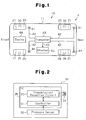
- Fig. 1 is a schematic structural diagram of a vehicle 10 including a tire status monitoring apparatus 1 according to one embodiment of the present invention.
- the tire status monitoring apparatus 1 includes four transponders (transmitters) 30 provided on respective tires 20 of the vehicle 10 and a single transceiver (receiver for the tire status monitoring apparatus) 40 provided on the body 11 of the vehicle 10.
- Each transponder 30 is fixed inside the associated tire 20, e.g., on the wheel 21 of the tire 20.
- Each transponder 30 measures the status of the associated tire 20, i.e., air pressure in the associated tire 20, and transmits transponder data including air pressure data acquired by the measurement.
- the transponder data is wirelessly transmitted to the transceiver 40 from each transponder 30.
- the transceiver 40 is provided at a predetermined location of the body 11 and operates on power from, for example, the battery (not shown) of the vehicle 10.
- the transceiver 40 has four antennae (reception units) 41 respectively corresponding to the four transponders 30. Each antenna 41 is connected to the transceiver 40 via a cable 42.
- the transceiver 40 generates a request signal at a predetermined time interval and transmits the request signal from each antenna 41.
- Each transponder 30 generates induced power based on the request signal and transmits transponder data using the induced power.
- the transceiver 40 receives the transponder data transmitted from each transponder 30 mainly via the associated antenna 41.
- a display 50 is placed in a visible range of the driver of the vehicle 10, such as in the passenger compartment.
- the display 50 is connected to the transceiver 40 via a cable 43.
- An engine 60 or the drive source of the vehicle 10 is mounted in the front portion of the vehicle 10.
- each transponder 30 includes a controller 31, a pressure sensor 32, a transmission/reception circuit 33 and a coil antenna 34.
- the controller 31 is, for example, a microcomputer including a CPU (Central Processing Unit), ROM (Read Only Memory) and RAM (Random Access Memory). Inherent ID codes are registered beforehand in the ROM. The ID codes are used to identify the four transponders 30 provided on the vehicle 10.
- the pressure sensor 32 measures the air pressure in the tire 20 and supplies the controller 31 with air pressure data acquired by the measurement.
- the controller 31 generates transponder data including the air pressure data and the ID code registered in the internal memory, and supplies the transmission/reception circuit 33 with the transponder data.
- the transmission/reception circuit 33 encodes and modulates the transponder data, then transmits the encoded and modulated transponder data via the coil antenna 34.
- the coil antenna 34 generates induced power based on, for example, the request signal sent from the associated antenna 41.
- the transmission/reception circuit 33 supplies the induced power to the controller 31.
- the controller 31 controls the transponder 30 with the supplied induced power. That is, the transponder 30 operates on the power induced in the coil antenna 34.
- the controller 31 and the transmission/reception circuit 33 are formed on a single-chip semiconductor substrate and integrated into an IC 35.
- the transceiver 40 includes a controller 44 which processes transponder data received via the antenna 41 and a transmission/reception circuit 45.
- the controller 44 is, for example, a microcomputer including a CPU, ROM and RAM. Inherent ID codes are registered in an internal memory, e.g., RAM, of the controller 44.
- the transmission/reception circuit (reception unit) 45 receives the transponder data from each transponder 30 mainly via the associated antenna 41.
- the transmission/reception circuit 45 demodulates and decodes the encoded and modulated transponder data, and then supplies the resultant transponder data to the controller 44.
- the controller 44 determines the air pressure of the tire 20 associated with the sender transponder 30.
- the controller 44 displays data about the air pressure on the display 50. In the case where the air pressure is particularly abnormal, warning of the event is displayed on the display 50.
- the controller 44 receives from a key cylinder 80 a signal (activation signal) indicating the ON action of a key switch 70 which activates the drive source of the vehicle 10, e.g., the engine 60.
- the controller 44 stores an inherent ID code included in transponder data into its own internal memory, e.g., RAM, when a predetermined condition is met. Therefore, an inherent ID code indicating the sender transponder 30 is registered in the internal memory of the controller 44.
- the controller 44 transmits a request signal to the transmission/reception circuit 45 from the antenna 41 at a predetermined time interval. Based on the request signal, induced power is generated in the coil antenna 34 of the transponder 30.
- the pressure sensor 32 measures air pressure in the tire 20 using that power.
- the transponder 30 transmits transponder data including air pressure data via the coil antenna 34.
- the transceiver 40 receives the transponder data transmitted from each transponder 30 mainly via the associated antenna 41.
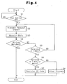
- transceiver 40 specifically, the controller 44 of the transceiver 40, will be described next referring to the flowchart shown in Fig. 4.
- the controller 44 determines if the key switch 70 which activates the engine 60 is turned on by the driver (S1). Specifically, the controller 44 determines if the activation signal from the key cylinder 80, originated from the ON action of the key switch 70, has been detected.
- the transceiver 40 When it is determined that the key switch 70 has been set to on (YES in S1), the transceiver 40 generates a request signal and sequentially transmits the request signal from the individual antennae 41 (S2). Then, induced power is generated in the coil antenna 34 of the transponder 30 corresponding to each antenna 41. With the induced power, the pressure sensor 32 of the transponder 30 measures air pressure inside the associated tire. The transponder 30 transmits transponder data including the measured air pressure data via the coil antenna 34.
- the transceiver 40 receives the transponder data, sent from the transponder 30, via the associated antenna 41 (S3).
- the controller 44 determines whether the ID code included in the received transponder data (hereinafter called a transponder ID code) matches with an ID code registered in the internal memory of the controller 44 (hereinafter called a registered ID code) (S4). In the case where the transponder ID code matches with the registered ID code (YES in S4), the transceiver 40 terminates the process.
- the controller 44 determines if the transponder data has been received by a first predetermined number of times (e.g., n times) (S5). In the case where the number of receptions of the transponder data has not reached the first predetermined number (NO in S5), the controller 44 returns to the process of step S2 and transmits the request signal.
- a first predetermined number of times e.g., n times
- the controller 44 determines that the ID code has been changed. That is, the controller 44 determines that the tire 20 having the transponder 30 has been changed. Specifically, the controller 44 determines that a new tire 20 has been attached to the vehicle 10. Alternatively, the controller 44 determines that the mounting position of the tire 20 with respect to the vehicle 10 has been changed. The controller 44 stores the changed ID code in the internal memory of the controller 44. As a result, the changed ID code is newly registered in the internal memory of the controller 44 (S7).
- the controller 44 executes other processes (S8).
- One of the other processes possible may be a process which does not change the registered ID code considering that the transponder ID code has not been changed. In this case, the registered ID code is not changed and the ID code registered at that time remains as it is until the key switch 70 is set to on once again.
- the transceiver 40 of the tire status monitoring apparatus 1 has the following advantages.
Landscapes
- Engineering & Computer Science (AREA)
- Mechanical Engineering (AREA)
- Arrangements For Transmission Of Measured Signals (AREA)
- Measuring Fluid Pressure (AREA)
Abstract
Description
- The above-described embodiment may be adapted to a
tire status monitoring apparatus that includes a plurality
of transmitters which are provided on the
respective tires 20, have batteries, measure the statuses of the associatedtires 20 and transmit data indicating the statuses of thetires 20 acquired in the measurement, and a receiver which receives data from those transmitters. - The
transceiver 40 may have a singlecommon antenna 41 with respect to the fourtransponders 30, or may have twoantennae 41 respectively provided at the front portion and rear portion of thevehicle 10. - The drive source may be a hybrid engine comprised of, for example, an engine and a motor, or may be a motor.
- The
transponder 30 may have a temperature sensor which measures the temperature inside the associatedtire 20 so that temperature data in thetire 20 is transmitted to thetransceiver 40. - The air pressure data may be data specifically indicating the value of the air pressure, or data simply indicating whether the air pressure lies within an allowable range or not.
- In the case where the transponder ID code does not
match with a registered ID code, the
controller 44 may determine that the transponder ID code has been changed and thetire 20 associated with the changed transponder ID code has been changed. - The vehicle may be a two-wheel bicycle or
motorcycle, a multi-wheel bus or tractor, or an industrial
vehicle or the like (e.g., a forklift) provided with
tires 20. In case where thetransponders 30 are provided on the tires of a tractor, thetransceiver 40 and thedisplay 50 are placed on the tractor. - The
transceiver 40 may be activated in accordance with the ON action of thekey switch 70 of thevehicle 10. In this case, after thekey switch 70 is set to on, thetransceiver 40 transmits a request signal to thetransponders 30 and executes the ID code determining process of the above-described embodiment.
Claims (17)
- A receiver (40) for a tire status monitoring apparatus that monitors statuses of a plurality of tires provided on a vehicle and includes a plurality of transmitters, provided on the tires respectively, for transmitting data indicating statuses of the respective tires, the data including an identification code to identify each tire, the receiver being supplied with an activation signal to activate a drive source of the vehicle and including a reception unit (41, 45) which receives the data from the transmitters, the receiver being characterized by:a control circuit (44) connected to the reception unit, wherein upon detection of the activation signal, the control circuit collates the identification code included in the data and specifies, based on the identification code, each transmitter which has transmitted the data.
- The receiver according to claim 1, characterized in that the reception unit (41, 45) transmits a request signal to each individual transmitter and receives the data in response to the request signal from each transmitter.
- The receiver according to claim 1 or 2, characterized in that the control circuit (44) has an identification code registered beforehand, determines whether or not the identification code included in the data matches with the registered identification code, and determines that the associated tire has been changed when those two identification codes do not match with each other.
- The receiver according to claim 3, characterized in that when it is determined that a tire has been changed, the control circuit (44) updates the registered identification code with the identification code included in the received data.
- The receiver according to claim 1, characterized in that the control circuit (44) has an identification code registered beforehand, determines whether or not the identification code included in the data matches with the registered identification code, determines whether or not those identification codes included in the data received by a first predetermined number of times match with one another a second predetermined number of times less than the first predetermined number of times or more when it is determined that those two identification codes do not match with each other, and determines that that tire which is associated with the identification code included in the data has been changed when it is decided that there have been such matches.
- The receiver according to claim 5, characterized in that when it is determined that a tire has been changed, the control circuit (44) updates the registered identification code with the identification code included in the received data.
- The receiver according to any one of claims 1 to 6, characterized in that the vehicle has a key cylinder (80) including a key switch (70) which generates the activation signal, and
the control circuit (44) receives the activation signal from the key cylinder when the key switch is set to on. - A tire status monitoring apparatus for monitoring statuses of a plurality of tires provided on a vehicle, the tire status monitoring apparatus including a plurality of transmitters (30) provided on the tires respectively, which detect statuses of the associated tires and transmit data indicating the detected statuses of the tires, and a receiver (40) provided on the vehicle, which receives the data from the plurality of transmitters, the data including an identification code to identify each tire, the tire status monitoring apparatus being characterized in that:wherein the receiver includes a control circuit (44), which, upon detection of the activation signal, collates the identification code included in the data and specifies, based on the identification code, each transmitter which has transmitted the data.the receiver (40) is supplied with an activation signal for activating a drive source of the vehicle,
- The tire status monitoring apparatus according to claim 8, characterized in that the receiver (40) transmits a request signal to each transmitter and receives the data in response to the request signal from each transmitter.
- The tire status monitoring apparatus according to claim 9, characterized in that the plurality of transmitters (30) generate power induced by the request signal and transmit the data using the generated power.
- The tire status monitoring apparatus according to any one of claims 8 to 11, characterized in that the control circuit (44) has an identification code registered beforehand, determines whether or not the identification code included in the data matches with the registered identification code, determines whether or not those identification codes included in the data received by a first predetermined number of times match with one another a second predetermined number of times less than the first predetermined number of times or more when it is determined that those two identification codes do not match with each other, and determines that that tire which is associated with the identification code included in the data has been changed when it is determined that there have been such matches.
- The tire status monitoring apparatus according to claim 11, characterized in that when it is determined that a tire has been changed, the control circuit (44) updates the registered identification code with the identification code included in the received data.
- The tire status monitoring apparatus according to any one of claims 8 to 12, characterized in that the vehicle has a key cylinder (80) including a key switch (70) which generates the activation signal, and
the control circuit (44) receives the activation signal from the key cylinder when the key switch is set to on. - A method of monitoring statuses of a plurality of tires (20) provided on a vehicle and including a plurality of transmitters (30) which generate data indicating statuses of the respective tires, the vehicle including a receiver (40) which receives the data from the transmitters, the data including an identification code to identify each tire, the method being characterized by the steps of:detecting an activation signal for activating a drive source of the vehicle;transmitting a request signal for generating the data and transmitting the data to the receiver to the plurality of transmitters, when the activation signal is detected;receiving the data from the plurality of transmitters;collating the identification code included in the data; andspecifying each transmitter which has transmitted the data, based on the identification code.
- The method according to claim 14, characterized in that the receiver has an identification code registered beforehand, and the collation step includes the steps of:determining whether the identification code included in the data matches with the registered identification code or not;receiving the data by a first predetermined number of times when it is determined that the two identification codes do not match with each other;determining whether or not those identification codes which are included in the data received by the first predetermined number of times do not match with one another a second predetermined number of times less than the first predetermined number of times or more; anddetermining that that tire which is associated with the identification code has been changed when it is determined that the identification codes match with one another the second predetermined number of times or more.
- The method according to claim 15, characterized in that the collation step further includes the step of updating the registered identification code with the identification code included in the received data when it is determined that a tire has been changed.
- The method according to any one of claims 14 to 16, characterized in that the vehicle has a key cylinder (80) including a key switch (70) which generates the activation signal, and
the step of detecting the activation signal detects the activation signal when the key switch is set to on.
Applications Claiming Priority (2)
| Application Number | Priority Date | Filing Date | Title |
|---|---|---|---|
| JP2003091993A JP2004299448A (en) | 2003-03-28 | 2003-03-28 | Receiver for tire condition monitoring device and tire condition monitoring device |
| JP2003091993 | 2003-03-28 |
Publications (3)
| Publication Number | Publication Date |
|---|---|
| EP1462279A2 true EP1462279A2 (en) | 2004-09-29 |
| EP1462279A3 EP1462279A3 (en) | 2005-03-23 |
| EP1462279B1 EP1462279B1 (en) | 2006-11-29 |
Family
ID=32821620
Family Applications (1)
| Application Number | Title | Priority Date | Filing Date |
|---|---|---|---|
| EP03023949A Expired - Lifetime EP1462279B1 (en) | 2003-03-28 | 2003-10-22 | Tire status monitoring apparatus and receiver therefor |
Country Status (4)
| Country | Link |
|---|---|
| US (1) | US6999861B2 (en) |
| EP (1) | EP1462279B1 (en) |
| JP (1) | JP2004299448A (en) |
| DE (1) | DE60310028T2 (en) |
Families Citing this family (16)
| Publication number | Priority date | Publication date | Assignee | Title |
|---|---|---|---|---|
| US7104438B2 (en) * | 2003-10-22 | 2006-09-12 | The Goodyear Tire & Rubber Company | Method of integrating tire identification into a vehicle information system |
| US7073377B2 (en) * | 2003-12-11 | 2006-07-11 | Trw Automotive U.S. Llc | Tire parameter sensing system with signal relay device and associated method |
| DE102004018827B4 (en) * | 2004-04-19 | 2006-06-29 | Siemens Ag | Device and method for determining the wheel position of wheels of a wheeled vehicle |
| JP4211683B2 (en) * | 2004-05-28 | 2009-01-21 | 株式会社デンソー | Communications system |
| US7219834B2 (en) * | 2004-11-04 | 2007-05-22 | Footprint Systems Inc. | System and method for tracking installed equipment and deploying spare parts |
| US20060206247A1 (en) * | 2005-03-09 | 2006-09-14 | Trw Automotive U.S. Llc | Tire parameter sensing system having a tire-based unit that is responsive to a trigger signal and associated method |
| JP4735301B2 (en) * | 2006-02-07 | 2011-07-27 | トヨタ自動車株式会社 | Vehicle control device |
| KR101121130B1 (en) * | 2009-12-03 | 2012-03-19 | 씨트론 주식회사 | System and method for detecting positions of tires |
| US9612321B2 (en) * | 2011-10-07 | 2017-04-04 | Siemens Aktiengesellschaft | Method for angle determination for moving assemblies, and apparatus |
| US8878664B1 (en) * | 2013-04-23 | 2014-11-04 | Cub Elecparts Inc. | Tire status receiving system |
| JP2015101209A (en) * | 2013-11-25 | 2015-06-04 | 株式会社東海理化電機製作所 | Tire position determination system |
| JP2015186991A (en) * | 2014-03-13 | 2015-10-29 | 株式会社東海理化電機製作所 | Tire position registration system |
| JP6569126B2 (en) * | 2015-12-15 | 2019-09-04 | 株式会社オートネットワーク技術研究所 | Tire pressure monitoring system, monitoring device and detection device |
| JP6569125B2 (en) * | 2015-12-15 | 2019-09-04 | 株式会社オートネットワーク技術研究所 | Tire pressure monitoring system, monitoring device and detection device |
| CN107554209B (en) * | 2016-07-01 | 2020-06-02 | 宝沃汽车(中国)有限公司 | Matching method of tire pressure sensor and tire, controller and automobile |
| US11110758B1 (en) * | 2020-10-19 | 2021-09-07 | Safran Landing Systems | System for monitoring the inflation pressure of the tires of an aircraft |
Family Cites Families (15)
| Publication number | Priority date | Publication date | Assignee | Title |
|---|---|---|---|---|
| US5612671A (en) | 1995-12-11 | 1997-03-18 | Delco Electronics Corp. | Method of learning tire pressure transmitter ID |
| DE19735686A1 (en) * | 1997-08-19 | 1999-02-25 | Doduco Gmbh | Identification allocation method especially for tire pressure monitoring system |
| DE69917997T2 (en) | 1998-08-25 | 2005-06-09 | Pacific Industrial Co., Ltd., Ogaki | System for air pressure control of tires |
| JP3401535B2 (en) | 1998-09-29 | 2003-04-28 | 太平洋工業株式会社 | Tire pressure monitoring system |
| US6292096B1 (en) * | 1999-12-15 | 2001-09-18 | Trw Inc. | Apparatus and method for transmitting data in a tire condition sensing system |
| EP2272688B1 (en) * | 2000-07-26 | 2012-02-01 | Bridgestone Americas Tire Operations, LLC | Electronic tire management system |
| US7015801B1 (en) | 2000-10-13 | 2006-03-21 | Trw Inc. | Vehicle-controlled tire condition sensor communication utilizing fixed tire identification |
| US6441728B1 (en) * | 2001-01-02 | 2002-08-27 | Trw Inc. | Tire condition sensor communication with tire location provided via vehicle-mounted identification units |
| EP1289780A1 (en) | 2001-04-26 | 2003-03-12 | Siemens VDO Automotive Corporation | Method of differentiating tires in a vehicle |
| TW552209B (en) * | 2001-05-17 | 2003-09-11 | Lite On Automotive Corp | Encoding device for a tire pressure monitor to be used in a vehicle with a tire monitor |
| EP1306234B1 (en) * | 2001-10-25 | 2004-12-22 | Pacific Industrial Co., Ltd. | Tire condition monitoring apparatus |
| US6612165B2 (en) * | 2002-02-04 | 2003-09-02 | Trw Inc. | Tire pressure monitoring system with pressure gauge operating mode for indicating when air pressure within a tire is within a predetermined pressure range |
| US6771169B1 (en) * | 2002-08-07 | 2004-08-03 | Ford Global Technologies, Llc | Tire pressure monitoring system with a signal initiator |
| US6809638B2 (en) * | 2002-08-20 | 2004-10-26 | Trw Inc. | Apparatus with receiver having selectable threshold time constant |
| US6750761B1 (en) * | 2003-02-25 | 2004-06-15 | Delphi Technologies, Inc. | Method for monitoring tire parameters |
-
2003
- 2003-03-28 JP JP2003091993A patent/JP2004299448A/en active Pending
- 2003-10-15 US US10/686,109 patent/US6999861B2/en not_active Expired - Lifetime
- 2003-10-22 EP EP03023949A patent/EP1462279B1/en not_active Expired - Lifetime
- 2003-10-22 DE DE60310028T patent/DE60310028T2/en not_active Expired - Lifetime
Also Published As
| Publication number | Publication date |
|---|---|
| DE60310028D1 (en) | 2007-01-11 |
| US6999861B2 (en) | 2006-02-14 |
| JP2004299448A (en) | 2004-10-28 |
| EP1462279B1 (en) | 2006-11-29 |
| EP1462279A3 (en) | 2005-03-23 |
| DE60310028T2 (en) | 2007-05-16 |
| US20040193341A1 (en) | 2004-09-30 |
Similar Documents
| Publication | Publication Date | Title |
|---|---|---|
| US6963274B2 (en) | Transmitter of tire condition monitoring apparatus and tire condition monitoring apparatus | |
| US6999861B2 (en) | Tire status monitoring apparatus and receiver therefor | |
| EP1419908B1 (en) | Method and apparatus for associating tires with tire locations of a vehicle | |
| US20030107481A1 (en) | Tire condition monitoring apparatus and method | |
| US6983649B2 (en) | Tire condition monitoring apparatus | |
| US7212105B2 (en) | Transmitter for tire condition monitoring apparatus | |
| EP2338704A1 (en) | Tire condition monitoring apparatus with keyless entry function | |
| US6954688B2 (en) | Tire status monitoring apparatus | |
| US6885292B2 (en) | Tire condition monitoring apparatus | |
| US6931923B2 (en) | Tire condition monitoring apparatus | |
| US7145446B2 (en) | Transponder for tire condition monitoring apparatus | |
| EP1336512A1 (en) | Tire condition monitoring apparatus | |
| JP3401535B2 (en) | Tire pressure monitoring system | |
| US7791460B2 (en) | Tire pressure monitoring system with reliable wireless communication between wheel-based transceivers and vehicle body-based transceiver | |
| JP2004098993A (en) | Tire pressure monitoring system and ID code registration method in tire pressure monitoring system | |
| EP1419906B1 (en) | Transmitting method of transmitter and processing method of receiver | |
| JP7124416B2 (en) | Sensor ID registration system | |
| JP2006232127A (en) | Tire pressure detector |
Legal Events
| Date | Code | Title | Description |
|---|---|---|---|
| PUAI | Public reference made under article 153(3) epc to a published international application that has entered the european phase |
Free format text: ORIGINAL CODE: 0009012 |
|
| AK | Designated contracting states |
Kind code of ref document: A2 Designated state(s): AT BE BG CH CY CZ DE DK EE ES FI FR GB GR HU IE IT LI LU MC NL PT RO SE SI SK TR |
|
| AX | Request for extension of the european patent |
Extension state: AL LT LV MK |
|
| PUAL | Search report despatched |
Free format text: ORIGINAL CODE: 0009013 |
|
| AK | Designated contracting states |
Kind code of ref document: A3 Designated state(s): AT BE BG CH CY CZ DE DK EE ES FI FR GB GR HU IE IT LI LU MC NL PT RO SE SI SK TR |
|
| AX | Request for extension of the european patent |
Extension state: AL LT LV MK |
|
| 17P | Request for examination filed |
Effective date: 20050425 |
|
| AKX | Designation fees paid |
Designated state(s): DE FR GB |
|
| GRAP | Despatch of communication of intention to grant a patent |
Free format text: ORIGINAL CODE: EPIDOSNIGR1 |
|
| GRAS | Grant fee paid |
Free format text: ORIGINAL CODE: EPIDOSNIGR3 |
|
| GRAA | (expected) grant |
Free format text: ORIGINAL CODE: 0009210 |
|
| AK | Designated contracting states |
Kind code of ref document: B1 Designated state(s): DE FR GB |
|
| REG | Reference to a national code |
Ref country code: GB Ref legal event code: FG4D |
|
| REF | Corresponds to: |
Ref document number: 60310028 Country of ref document: DE Date of ref document: 20070111 Kind code of ref document: P |
|
| ET | Fr: translation filed | ||
| PLBE | No opposition filed within time limit |
Free format text: ORIGINAL CODE: 0009261 |
|
| STAA | Information on the status of an ep patent application or granted ep patent |
Free format text: STATUS: NO OPPOSITION FILED WITHIN TIME LIMIT |
|
| 26N | No opposition filed |
Effective date: 20070830 |
|
| PGFP | Annual fee paid to national office [announced via postgrant information from national office to epo] |
Ref country code: FR Payment date: 20141008 Year of fee payment: 12 Ref country code: GB Payment date: 20141022 Year of fee payment: 12 Ref country code: DE Payment date: 20141014 Year of fee payment: 12 |
|
| REG | Reference to a national code |
Ref country code: DE Ref legal event code: R119 Ref document number: 60310028 Country of ref document: DE |
|
| GBPC | Gb: european patent ceased through non-payment of renewal fee |
Effective date: 20151022 |
|
| PG25 | Lapsed in a contracting state [announced via postgrant information from national office to epo] |
Ref country code: DE Free format text: LAPSE BECAUSE OF NON-PAYMENT OF DUE FEES Effective date: 20160503 Ref country code: GB Free format text: LAPSE BECAUSE OF NON-PAYMENT OF DUE FEES Effective date: 20151022 |
|
| REG | Reference to a national code |
Ref country code: FR Ref legal event code: ST Effective date: 20160630 |
|
| PG25 | Lapsed in a contracting state [announced via postgrant information from national office to epo] |
Ref country code: FR Free format text: LAPSE BECAUSE OF NON-PAYMENT OF DUE FEES Effective date: 20151102 |