EP1462265A2 - Image forming apparatus and image forming method - Google Patents
Image forming apparatus and image forming method Download PDFInfo
- Publication number
- EP1462265A2 EP1462265A2 EP04006902A EP04006902A EP1462265A2 EP 1462265 A2 EP1462265 A2 EP 1462265A2 EP 04006902 A EP04006902 A EP 04006902A EP 04006902 A EP04006902 A EP 04006902A EP 1462265 A2 EP1462265 A2 EP 1462265A2
- Authority
- EP
- European Patent Office
- Prior art keywords
- image
- correction
- recording
- image forming
- recording element
- Prior art date
- Legal status (The legal status is an assumption and is not a legal conclusion. Google has not performed a legal analysis and makes no representation as to the accuracy of the status listed.)
- Withdrawn
Links
Images






Classifications
-
- H—ELECTRICITY
- H04—ELECTRIC COMMUNICATION TECHNIQUE
- H04N—PICTORIAL COMMUNICATION, e.g. TELEVISION
- H04N1/00—Scanning, transmission or reproduction of documents or the like, e.g. facsimile transmission; Details thereof
- H04N1/40—Picture signal circuits
- H04N1/401—Compensating positionally unequal response of the pick-up or reproducing head
- H04N1/4015—Compensating positionally unequal response of the pick-up or reproducing head of the reproducing head
-
- B—PERFORMING OPERATIONS; TRANSPORTING
- B41—PRINTING; LINING MACHINES; TYPEWRITERS; STAMPS
- B41J—TYPEWRITERS; SELECTIVE PRINTING MECHANISMS, i.e. MECHANISMS PRINTING OTHERWISE THAN FROM A FORME; CORRECTION OF TYPOGRAPHICAL ERRORS
- B41J2/00—Typewriters or selective printing mechanisms characterised by the printing or marking process for which they are designed
- B41J2/435—Typewriters or selective printing mechanisms characterised by the printing or marking process for which they are designed characterised by selective application of radiation to a printing material or impression-transfer material
- B41J2/447—Typewriters or selective printing mechanisms characterised by the printing or marking process for which they are designed characterised by selective application of radiation to a printing material or impression-transfer material using arrays of radiation sources
Definitions
- the present invention relates to an image forming apparatus and an image forming method.
- the recording element usually has variation of 20% - 40%, and when trying to reproduce a photograph in continuous tone, it is necessary to correct the variation by lowering it to the value of at most 2% or less, and when trying to acquire higher quality, it is necessary to correct the variation by lowering it to the lower value of 1% or less. Technologies concerning this correction are disclosed in Patent Documents 1 - 3.
- Patent Document 3 Patent Document 3
- recording elements need to be arranged at a certain interval of about 85 ⁇ for 300 dpi, for example, so that recording may be conducted at desired resolution.
- a photosensitive material is a silver halide color photo paper
- a beam spot is blurred by halation wherein light transmitted through a photosensitive layer is reflected on a reflection support to expose the photosensitive layer to light, because the reflection support is present in the photo paper. Therefore, the aforesaid difficulty is further increased.
- a selfoc lens is frequently used for an image forming optical system of a print head that is equipped with recording elements in an array form, and since a light image composed by each of the selfoc lens is exposed on a photosensitive material, inconsiderable shift of position caused by a curl of a photosensitive material and fluctuation in the course of transport of a photosensitive material have an adverse effect on a deviation of a focal point of a beam spot and on blurring of an image
- pixels are overlapped in the course of image output, and density is higher than the circumference on the portion where an overlapped area for the pixels is relatively large, while density is lower on the portion where an overlapped area is small, which rather causes possibility of occurrence of density unevenness.
- An object of the invention is to provide an image forming apparatus wherein density unevenness, density unevenness of high-frequency components in particular are reduced effectively, and unevenness-converging speed of the density unevenness is high, and to provide an image forming method.
- the invention is one to realize vast improvements in density unevenness by taking in an influence of adjoining recording elements positively on an image for correction and thereby by correcting density unevenness. Structures of the invention are not disclosed or suggested in the conventional technologies described above.
- An image forming apparatus having: a print head comprising a plurality of recording elements arranged in an array, each of the plurality of recording elements being operated based on respective each correction coefficient of light amount; and an image reading apparatus for reading an image recorded on photosensitive material; wherein, the image forming apparatus records an image for correction onto the photosensitive material by using the print head, acquires read information D (i) of the image for correction recorded (where, "i" is a natural number indicating an arraying order of each of the plurality of recording elements) through the image reading apparatus, acquires a correction amount C (i) for a recording characteristic of each of the plurality of recording elements based on the read information D (i) acquired, and records an image by using the correction amount C (i) acquired; wherein, the image recording apparatus acquires the correction amount C (i) for the recording characteristic of i-th recording element by using the read information D (i) and read information D (k) corresponding to another one of the plurality of recording elements (where, "k” is a different natural number from "i
- the invention for solving the problem is represented by an image forming method including the steps of: recording an image for correction onto photosensitive material by using a print head comprising a plurality of recording elements arranged in an array, each of the plurality of recording elements being operated based on respective each correction coefficient of light amount; acquiring read information D (i) of the image for correction recorded (where, "i” is a natural number indicating an arraying order of each of the plurality of recording elements) through reading the image; acquiring a correction amount C (i) for a recording characteristic of each of the plurality of recording elements based on the read information D (i) acquired; and recording an image by using the correction amount C (i) acquired; wherein, the correction amount C (i) for the recording characteristic of i-th recording element is acquired by using the read information D (i) and read information D (k) corresponding to another one of the plurality of recording elements (where, "k” is a different natural number from “i”).
- the read information in the invention means information showing optical density which has been read by any of density-measuring means, or numerical information calculated based on optical density, and it may also be optical density itself, reflectance, transmission factor, light absorption factor, functional value in one-to-one correspondence to the foregoing, for example, logarithmic value, or a statistical amount such as the mean value or a correction amount in the invention. Further, when conducting measurement through reading of images by using an image reading apparatus such as a flat-bed scanner, read information may also be a signal value obtained through measurement by an image reading apparatus, a functional value in one-to-one correspondence to the signal value, for example, a logarithmic value, or a relative value of the foregoing.
- Figs. 7 (a)- 7 (c) show schematically a print head in which recording elements are arranged in an array form.
- the array form includes not only a form of a straight line shown in Fig. 7 (a) but also a zigzag arrangement shown in Fig. 7 (b) and an arrangement shown in Fig. 7 (c). Further, in each arrangement, there is assigned to each recording element a number showing an order of arrangement of recording elements illustrated.
- a solid image in the invention is an image that is formed when recording elements arranged continuously as shown in Figs. 7 (a)- 7 (c) record on a photosensitive material without placing any intervals. Namely, it is an image that is formed when recording elements in which the numbers each showing an order of arrangement are continuous record on a photosensitive material.
- a long side of the rectangle is in parallel with the direction of arrangement of light-receiving elements (CCD) of the image reading apparatus.
- a print head having thereon recording elements arranged in an array form may be one wherein plural recording elements are arranged in one row or in plural rows at prescribed intervals for obtaining desired resolution, and as a preferable example of the print head having thereon recording elements arranged in an array form, there are given an optical shutter array such as PLZT print head employing those in which LED light-emitting elements or vacuum fluorescent tubes are arranged or employing an appropriate backlight or employing liquid crystal shutter array print head, those on which semiconductor lasers are arranged in an array form, a thermal head, and a light-emitting element utilizing electroluminescence phenomenon such as organic EL material. Further, an apparatus capable of forming images with plural gradations such as an apparatus to record on a silver halide photosensitive material by using various types of recording element arrays and an apparatus to record with a thermal head by using sublimation ink are especially preferable.
- an optical shutter array such as PLZT print head employing those in which LED light-emitting elements or vacuum fluorescent tubes are arranged or employ
- Plural print heads in the case of recording on a photosensitive material by using plural print heads may either be one wherein plural print heads each being for a different color are present, or be one wherein plural print heads each being for the same color are present.
- print heads for respective basic colors of RGB may also be present.
- a print head to record on a recording material by using a common print head through switching of light with plural wavelengths is regarded as one wherein plural print heads are present.
- images may also be one wherein a pixel interval whose length is at least one recording element or more is formed in the direction of the recording element, and pixels are arranged separately with intervals, but solid images having no intervals are preferable.
- images may be any one provided that the image is solid, and the image having the same density in the direction of recording elements as far as possible is preferable.
- the image to be used mainly for correction of density unevenness of a print head is preferable.
- a length (LV) in the direction perpendicular to the direction of arrangement of recording elements of a print head is not so long for a length (LH) in the direction of arrangement of recording elements of a print head with respect to a size of a photosensitive material on which an image is recorded, and from viewpoints of transportability of photosensitive materials, reduction of loss paper and an influence on development processing, a ratio of LV/LH that is within 2 is preferable, a ratio within 1.2 is more preferable, and 0.9 is further more preferable.
- a correction amount is present in each recording element, and it is one to adjust the light amount correction coefficient of each recording element so that each recording element can record on a photosensitive material with a uniform exposure amount. It is preferable that the correction amount is adjusted sufficiently, and due to this, uniform solid images can be obtained.
- the light amount correction coefficient in the invention is a coefficient for controlling exposure amount by each recording element, and control of the exposure amount by controlling exposure time, for example, is preferable.
- each recording element may have its own individual light amount correction coefficient.
- the read information D (i) of the images for correction is density information.
- the read information D (i) of the images for correction is density information.
- Density information in this case means optical density obtained through reading by an optional image reading apparatus, and it may also be reflectance, transmission factor, light absorption factor, functional value in one-to-one correspondence to the foregoing, such as logarithmic value, though it may be optical density itself.
- Density obtained by conducting measurement by reading images by the use of an image reading apparatus may also be a signal value obtained through measurement by an image reading apparatus, and it may be a functional value in one-to-one correspondence to the signal value, for example, a logarithmic value. Further, as density in this case, optical density whose linearity is relatively high is preferable, and a logarithmic value of a signal value measured by an image reading apparatus, or optical density is given as a preferable example.
- the images for correction are recorded so that an influence exerted on a pixel recorded by i th recording element by a pixel recorded by another recording element arranged to be apart from the aforesaid recording element may be constant for all recording elements wherein i is arbitrary.
- the images for correction are recorded so that an influence exerted on a pixel recorded by i th recording element by a pixel recorded by another recording element arranged to be apart from the aforesaid recording element may be constant for all recording elements wherein i is arbitrary.
- a degree of an influence exerted by an interval of separated pixels is constant
- an overlapping degree is given to read information D (i) of i th recording element by certain parameter ⁇ for a pixel that is apart by a distance equivalent to one recording element, and an influence of the pixel that is apart by a distance equivalent to two recording elements is given by certain parameter ⁇ , both for read information E (i) of i th recording element to be used for correction calculation, as shown in the following numerical expression I, for example.
- Parameters ⁇ and ⁇ are sometimes called an adjacent contribution factor in the following.
- read information D (i) for the i th recording element is obtained from a pixel recorded by the i th recording element and from a pixel recorded by another adjoining recording element.
- read information D (i) for the i th recording element is obtained from a pixel recorded by the i th recording element and from a pixel recorded by another adjoining recording element.
- an adjoining pixel in the invention means a recording element having a consecutive number. Even in the case of zigzag arrangement in two rows as shown in Fig. 7 (b), such adjoining pixel means a recording element having a consecutive number.
- Read information E (i) of i th recording element used for calculation of correction may be any information, but, there is a piece of information calculated by the use of the following numerical expression, as a preferable example.
- Numerical expression II; E (i) D (i) + 2 ⁇ D (i) - ⁇ D (i + 1) - ⁇ D (i - 1))
- the invention described in either one of the features (1) - (4) has a means to change a degree of influence of the pixel recorded by another recording element arranged to be close to the i th recording element, as in the invention described in the feature (5), and it is preferable that the invention described in either one of the features (12) - (15) has a means to change a degree of influence of the pixel recorded by another recording element arranged to be close to the i th recording element, as in the invention described in the feature (16).
- means to change a rate of contribution there is given, for example, means to change parameters ⁇ and ⁇ in the numeral expressions I and II.
- the image reading apparatus is provided with a pressure member for setting the images for correction onto the image reading apparatus.
- an edge decision can be conducted accurately, and precision of correction is improved accordingly. Further, density unevenness of low-frequency components can be reduced substantially.
- the pressure member is a member to hold images for correction. It is preferable that this pressure member is, for example, black in color and has density that is substantially uniform. AS a material of the pressure member, a soft material that can be crooked freely such as, for example, rubber or a sponge is preferable. Due to the aforementioned features, an edge decision can be conducted accurately, and precision of correction is improved accordingly.
- an image for correction turns out to be small, and thereby, an image forming apparatus can be made small.
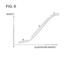
- a value shown by the read information obtained from the images for correction is set on a straight line portion (a large gradient range) of the characteristic curve of the photosensitive material.
- a value shown by the read information obtained from the images for correction is set on a straight line portion (a large gradient range) of the characteristic curve of the photosensitive material.
- the one wherein a line-shaped CCD is provided and images are read when the line-shaped CCD scans such as a flat-bed scanner or a drum scanner is preferable.
- the image reading apparatus When measuring density of images for correction by using the image reading apparatus, it is preferable to read images for correction at the resolution (for example, 1200 dpi) that is higher than the resolution (for example, 300 dpi) recorded on a photosensitive material by using a print head in which recording elements are arranged in an array form.
- the resolution for example, 1200 dpi
- the resolution for example, 300 dpi
- Image forming apparatus 100 in the present embodiment will be explained as follows.
- Fig. 1 and Fig. 2 show a schematic structure of image forming apparatus 100.
- the image forming apparatus 100 is composed of supporting drum 1, red print head 30a, green print head 30b, blue print head 30c, print head control section 40, correction processing section 60 and image reading apparatus 70.
- photo paper 2 representing a silver halide photographic photosensitive material fed out of a roll of the supporting drum 1 is conveyed in the direction shown with an arrow by the supporting drum 1 that is rotated by an unillustrated driving source
- red print head 30a, green print head 30b and blue print head 30c give exposure on prescribed positions on photo paper 2 in succession based on exposure control corresponding to image information for output by print head control section 40, to form latent images for color images on the photo paper 2.
- the photo paper 2 is conveyed by the supporting drum 1 to developing process.
- Each of red print head 30a, green print head 30b and blue print head 30c has a light source serving as recording elements arranged in an array form in one row or two rows.
- a light source serving as recording elements arranged in an array form in one row or two rows.
- an LED light source on the red print head 30a, there is used an LED light source, and on each of the green print head 30b and the blue print head 30c, there is used a vacuum fluorescent print head that can be subjected to color separation easily by a color filter under the conditions of relatively high luminance and high speed response.
- the photo paper 2 may also be sheet paper without being limited to roll paper, and a conveyance method for photo paper 2 is not restricted in particular.
- the red print head 30a is composed of shift register 31, latch circuit 32, driver circuit 33, recording element array 34, selfoc lens array 35, as shown in Fig. 2.
- the foregoing also applies to the green print head 30b and the blue print head 30c in the same way, in addition to the red print head 30a.
- red print head 30a (also in the green print head 30b and the blue print head 30c), when data of MSB (most significant bit) are transmitted to shift register 31 from print head control section 40 as image bit data for one line, a set pulse signal is inputted in latch circuit 32 from print head control section 40, and data of the aforementioned MSB for one line are latched collectively in latch circuit 32 in synchronization with the set pulse signal.
- the image bit data in this case mean data of a specific bit among image information for output.
- driver circuit 33 transmits driving signals to a recording element in recording element array 34 with a selected latched data of "1" to emit light for a period of time of enabling signals. Emitted light forms an image on photo paper 2 through selfoc lens array 35, thus, a latent image is formed.
- the print head control section 40 converts the inputted image information into 12-bit image information for output based on output value conversion LUT (Look Up Table) including exposure amount information.
- the image information for output represents serial digital data equivalent to one line for each bit data, and it generates a set pulse signal for transmitting image bit data to latch circuit 32 and generates an enabling signal for controlling emission time, and these image bit data, a set pulse signal and an enabling signal are outputted to each of the red print head 30a, the green print head 30b and the blue print head 30c.
- the print head control section 40 controls the enabling signal to adjust light emission characteristics of the red print head 30a, the green print head 30b and the blue print head 30c.
- print head control section 40 conducts recording control while shifting exposure timing for the red print head 30a, the green print head 30b and the blue print head 30c, so that image information transmitted for each color is recorded on a prescribed position on the photo paper 2. Due to this, color images can be recorded on photo paper 2 appropriately.
- the correction processing section 60 calculates light amount correction coefficient for correcting light emission characteristics of the red print head 30a, the green print head 30b and the blue print head 30c from density information, and outputs it to the print head control section 40.
- the image for correction 2a is one recorded on photo paper 2 by image forming apparatus 100 and is used when an amount of correction for the light amount correction coefficient or for the exposure amount is calculated.
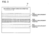
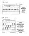
- the image for correction 2a may either be one wherein it is recorded by each of the red print head 30a, the green print head 30b and the blue print head 30c individually as shown in Fig. 3, and it is colored by dye for each of basic colors of YMC, or be one wherein the images for correction are recorded by the red print head 30a, the green print head 30b and the blue print head 30c simultaneously as shown in Fig. 4 (a), and the images for correction are colored by dyes of basic colors at the same position.
- the image for correction 2a has a marker section that clarifies an order of arrangement of respective recording elements of the red print head 30a, the green print head 30b and the blue print head 30c, and specifies each recording element individually, for specifying density corresponding to each of recording elements respectively for the red print head 30a, the green print head 30b and the blue print head 30c.
- a small interval such as, for example, the interval of 10 pixels or less is preferable from the viewpoint of the aforementioned purpose of use, the interval of 5 pixels or less is more preferable and, the interval of 1 pixel is most preferable.
- the interval of 1 pixel means a repetition of ON, OFF, ON, OFF ⁇ ⁇ for one pixel.
- image for correction 2a has a marker section for each of the red print head 30a, the green print head 30b and the blue print head 30c, because it is feared that errors to some extent may be included in mounting accuracy for each of the red print head 30a, the green print head 30b and the blue print head 30c.
- the image for correction 2a has a marker section for each basic color, namely, for each of the red print head 30a, the green print head 30b and the blue print head 30c.
- a plurality of marker sections may also be present.
- the print head is constituted by recording on plural positions, it is preferable to make the marker section to be present in the vicinity of the recorded position, and to make the markers to be present at plural positions, and it is preferable to make the marker to be present between the recorded positions.
- the image for correction 2a When a plurality of marker sections are present, it is preferable for the image for correction 2a that the plural marker sections mentioned above are recorded (printed) by the same recording element.
- the image for correction 2a is recorded on cut (sheet-shaped) photo paper 2 of a cut (sheet-shaped) type not of a roll-shaped type, it is preferable that the image for correction 2a is recorded at the central portion of the photo paper 2 as far as possible, and it is further possible that a non-recorded area is formed in the forefront of the photo paper 2.
- each of basic colors YMC is recorded individually on the image for correction 2a by each of the red print head 30a, the green print head 30b and the blue print head 30c as the image for correction 2a, it is preferable, from the viewpoint of developability, to convey to a development processing apparatus so that a portion composed of Y dye may be processed finally.
- the image for correction 2a that plural image data are recorded separately at plural respective different areas, and it is preferable, from the viewpoint of simplification of calculation processing, to record in an order from image data recorded at low density to image data recorded at high density in succession, and it is further preferable, from the viewpoint of developability, to convey to the development processing apparatus so that a portion recorded at lower density may be processed earlier.
- a range for density measurement for the image for correction 2a is as broad as possible, and the number of positions for density measurement for the image for correction 2a is as many as possible. Further, it is preferable that the number of lines to be recorded is in a range of 50 - 1000, and a range of 50 - 200 is more preferable and a range of 60 - 100 is further preferable. Further, it is preferable that 10% - 90% of the number of lines recorded are subjected to density measurement for obtaining a correction amount for the light amount correction coefficient and for the exposure amount, and a range of 20% - 80% is more preferable.
- density from 0.3 to 1.5 is preferable, that from 0.4 to 1.0 is more preferable and that from 0.5 to 0.7 is most preferable for R (Red), density from 0.2 to 1.5 is preferable, that from 0.3 to 0.8 is more preferable and that from 0.4 to 0.6 is most preferable for G (Green), and density from 0.15 to 1.5 is preferable, that from 0.3 to 1.0 is more preferable and that from 0.4 to 0.6 is most preferable for B (Blue).
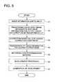
- Image forming processing by image forming apparatus 100 will be explained as follows, referring to the flow chart shown in Fig. 5.
- print head control section 40 converts the inputted image information to image information for output based on output value conversion LUT (step S2).
- the print head control section 40 controls an enabling signal and adjusts light emission characteristics for each of the red print head 30a, the green print head 30b and the blue print head 30c (step S3).
- the print head control section 40 transmits image information for output for each of the aforesaid colors to each of the red print head 30a, the green print head 30b and the blue print head 30c (step S4), and records on photo paper 2 (step S5).
- step S6 the photo paper 2 on which the image for output is recorded is subjected to development processing (step S6), and this image forming processing is completed (step S7) when development is finished (step S7).
- Experiment Example 1 when obtaining light amount correction coefficient C (i) of i th recording element from the state of inferior density unevenness (density unevenness for each of B and G is satisfactory) by using image for correction 2a shown in Fig. 3, for red print head 30a based on calculation processing shown in the flow chart in Fig. 6, density unevenness after correction of the light amount correction coefficient (visual evaluation on a portrait including gradation of gray) and necessary frequency of corrections were compared between the case where the read information other than read information D (i) of the i th recording element is used and the case where the read information is not used.
- read information used in processing in step S 14 illustrated in the flow chart in Fig. 6 is a scanner signal value.
- Results of the Experiment Examples 1 show that density unevenness of high-frequency components was decreased when C (i) was calculated by using read information other than read information D (i) of the i th recording element.
- the number of corrections was four when read information other than read information D (i) of the i th recording element was used, and it was eight when the read information other than read information D (i) of the i th recording element was not used.
- the calculation processing is carried out by correction processing section 60 for each of the red print head 30a, the green print head 30b and the blue print head 30c.
- the correction processing section 60 After receiving image information of image for correction 2a scanned by image reading apparatus 70 (step S 10), the correction processing section 60 specifies, from the image information thus received, a position on the image for correction 2a of each recording element (hereinafter, i th recording element is called recording element (i)), based on image information relating to a marker section of the image for correction 2a (step S11).
- step S 11 the correction processing section 60 specifies scanner read value S (i) corresponding to recording element (i) (step S12).
- the correction processing section 60 calculates density E (i) based on the read information D (i) by using Numerical expression I (step S14).
- Experiment Example 2 was conducted by the use of images for correction 2a shown in Fig. 4 for five occasions including (1) an occasion where the read information is scanner signal value, (2) an occasion where the read information is a logarithmic value of the scanner signal value, (3) an occasion where the read information is a squared value of the scanner signal value, (4) an occasion where the read information is correction value C (i) (C (i) was obtained without considering contribution of neighboring pixels) and (5) an occasion where the read information is a logarithmic value of the scanner signal value, but contribution of neighboring pixels is not considered.
- read information in the present experiment example 2 is optical density or a logarithmic value such as a scanner signal value.
- red print head 30a and green print head 30b are made to be selected by software through a program.
- Experiment Example 5 was conducted after photo paper 2 having thereon image for correction 2a recorded was held by a black pressure member such as rubber on an unillustrated reading portion of image forming apparatus 70. Owing to this, an edge portion was corrected properly, and a lift and skewing of paper were reduced. Thus, unevenness of low-frequency components was reduced.
- FIG. 9 An evaluation standard for density unevenness evaluation shown in Fig. 9 will be explained below. “A” shows that density unevenness does not exist at all and image quality is extremely excellent, “B” shows that image quality is remarkably excellent though slight density unevenness is observed partially, “C” shows that image quality is excellent though slight density unevenness is observed, and “D” shows that density unevenness is observed and image quality is not desirable.
- Experiment Example 7 will be explained.
- a silver halide photosensitive material was used as a photosensitive material of photo paper 2 on which image for correction 2a is recorded. Owing to this, more effect of the invention was exhibited.
- Experiment Example 8 will be explained.
- a reflection support was used as a photosensitive material of photo paper 2 on which image for correction 2a is recorded. Owing to this, more effect of the invention was exhibited.
- Experiment Example 9 was conducted in the same way as in the Experiment Example 3, for three occasions wherein density of image for correction 2a used for processing in step S 10 in the flow chart in Fig. 6 is low (1) (representing a nonlinear portion shown with symbol B in the diagram in Fig. 8), medium (2) (representing a linear portion shown with symbol A in the diagram in Fig. 8), and high (3) (representing a nonlinear portion shown with symbol C in the diagram in Fig. 8).
- density unevenness correction and setting up are carried out by considering overlapping (adjacent contribution) of pixels of recording elements each being recorded on photo paper 2.
- photo paper 2 is a color photo paper with a silver halide photosensitive material
- a beam spot is blurred by halation wherein light transmitted through a photosensitive layer is reflected on a reflection support to expose the photosensitive layer to light, because the reflection support is present in the photo paper. Even in this case, it is possible to measure accurately and feed back accurately the density corresponding to each recording element.
- a selfoc lens is used in many cases, and image forming light formed by the selfoc lens is made to form on a photosensitive material. Even in cases where a selfoc lens is used, an adverse effect on focus shifting of a beam spot and on bleeding of image can be avoided, even for delicate positional deviation caused by curl of photosensitive material of photo paper 2, or for variation in the course of transport of photosensitive materials.
- the invention has an effect for reduction of density unevenness, especially for reduction of density unevenness of high-frequency components, and it is possible to realize an image forming method and an image forming apparatus wherein a converging speed for density unevenness is high. Following upon this, it is possible to manufacture digital minilab equipment which can be put to practical use.
- Image forming apparatus 200 is composed of white light source 110, color filter 115, optical fiber array 120, PLZT shutter array 130, selfoc lens array 140, conveyance means 150, filter switching controller 160, image data output controller 170, transport controller 180, exposure controller 190, correction processing section 60 and image reading apparatus 70.
- light emitted from white light source 110 and transmitted through rotary color filter 115 passes through optical fiber array 120 to be guided to PLZT shutter array 130, and gives exposure on the prescribed position on photo paper 102.
- the exposure is given on photo paper 102 that is conveyed in the direction of arrow X by conveyance means 150 which is interlocked with a driving source (not shown) to rotate.
- Color filter 115 is in a form of a disc, and the disc is divided into three equal sectors each having an angle of circumference of 120° and having each color of red (R), green (G) and blue (B), and a center shaft of the disc is connected with a driving source (not shown).
- a driving source not shown.
- Optical fiber array 120 guides light of each color in RGB that has passed through color filter 115 to PLZT shutter array 130.
- a plurality of PLZT elements are arranged in an array form in one row in the direction (the direction of arrow Y in Fig. 10) perpendicular to the conveyance direction (the direction of arrow X in Fig. 10) for photo paper 102.
- Each PLZT element is arranged at an interval corresponding to a pixel.
- the PLZT element is an optical shutter, and its transmission factor for light varies depending on impressed voltage. Exposure is given while the PLZT element is transmitting light. Exposure time is controlled corresponding to image data, and gradation is expressed. For example, when expressing lower density, shorter exposure time is required.
- Light transmitted through the PLZT shutter array 130 forms an image on photo paper 102 through selfoc lens array 140.
- Filter switching controller 160 rotates color filter 115 in accordance with image data in respective exposure colors of RGB, and switches a color of light for exposure in succession.
- Image data output controller 170 controls exposure time by changing voltage to be impressed on PLZT shutter array 130 in accordance with image data in respective exposure colors of RGB.
- Photo paper transport controller 180 controls transport means 150.
- Exposure controller 190 updates a light amount correction coefficient based on an amount of correction calculated by correction processing section 60, and it controls simultaneously, based on the updated light amount correction coefficient, the filter switching controller 160, image data output controller 170 and transport controller 180. Thus, exposure is given to prescribed positions on 102 for each color, and a latent image for a color image is formed on the 102. After completion of the exposure process, the 102 is transported to a developing process representing a following process.
- image forming apparatus 200 a calculation method for an amount of correction in correction processing section 60 and a method of acquiring read information in image reading apparatus 70 are the same as those in the image forming apparatus 100, though the structure of the portion to give exposure is different. Therefore, explanation thereof will be omitted here.
- a photosensitive material of photo paper 2 is a silver halide color photo paper
- a beam spot is blurred by halation wherein light transmitted through a photosensitive layer is reflected on a reflection support to expose the photosensitive layer to light, because the reflection support is present in the photo paper. Even in this case, it is possible to measure accurately and feed back accurately the density corresponding to each recording element.
- a selfoc lens is used in many cases, and image forming light formed by the selfoc lens is made to form on a photosensitive material, therefore, an adverse effect on focus shifting of a beam spot and on bleeding of image can be avoided, even for delicate positional deviation caused by curl of photosensitive material of photo paper, or for variation in the course of transport of photosensitive materials.
- the invention has an effect for reduction of density unevenness, especially for reduction of density unevenness of high-frequency components, and it is possible to realize an image forming method and an image forming apparatus wherein a converging speed for density unevenness is high.
Landscapes
- Health & Medical Sciences (AREA)
- General Health & Medical Sciences (AREA)
- Toxicology (AREA)
- Engineering & Computer Science (AREA)
- Multimedia (AREA)
- Signal Processing (AREA)
- Printers Or Recording Devices Using Electromagnetic And Radiation Means (AREA)
- Facsimile Image Signal Circuits (AREA)
- Control Of Exposure In Printing And Copying (AREA)
- Fax Reproducing Arrangements (AREA)
Abstract
Description
wherein light transmitted through a photosensitive layer is reflected on a reflection support to expose the photosensitive layer to light, because the reflection support is present in the photo paper. Therefore, the aforesaid difficulty is further increased.
wherein, the image forming apparatus records an image for correction onto the photosensitive material by using the print head, acquires read information D (i) of the image for correction recorded (where, "i" is a natural number indicating an arraying order of each of the plurality of recording elements) through the image reading apparatus, acquires a correction amount C (i) for a recording characteristic of each of the plurality of recording elements based on the read information D (i) acquired, and records an image by using the correction amount C (i) acquired;
wherein, the image recording apparatus acquires the correction amount C (i) for the recording characteristic of i-th recording element by using the read information D (i) and read information D (k) corresponding to another one of the plurality of recording elements (where, "k" is a different natural number from "i").
wherein, the correction amount C (i) for the recording characteristic of i-th recording element is acquired by using the read information D (i) and read information D (k) corresponding to another one of the plurality of recording elements (where, "k" is a different natural number from "i").
Further, an apparatus capable of forming images with plural gradations such as an apparatus to record on a silver halide photosensitive material by using various types of recording element arrays and an apparatus to record with a thermal head by using sublimation ink are especially preferable.
Parameters α and β are sometimes called an adjacent contribution factor in the following.
On the
Claims (22)
- An image forming apparatus comprising:wherein, the image forming apparatus records an image for correction onto the photosensitive material by using the print head, acquires read information D (i) of the image for correction recorded (where, "i" is a natural number indicating an arraying order of each of the plurality of recording elements) through the image reading apparatus, acquires a correction amount C (i) for a recording characteristic of each of the plurality of recording elements based on the read information D (i) acquired, and records an image by using the correction amount C (i) acquired;a print head comprising a plurality of recording elements arranged in an array, each of the plurality of recording elements being operated based on respective each correction coefficient of light amount; andan image reading apparatus for reading an image recorded on photosensitive material;
wherein, the image recording apparatus acquires the correction amount C (i) for the recording characteristic of i-th recording element by using the read information D (i) and read information D (k) corresponding to another one of the plurality of recording elements (where, "k" is a different natural number from "i"). - The image forming apparatus of claim 1, wherein the read information D (i) of the image for correction is density information.
- The image forming apparatus of claim 1 or 2, wherein the image for correction is recorded in such a way that a degree of influence to a first pixel recorded by the i-th recording element from a second pixel recorded by the other recording element is made constant for any of the plurality of recording elements with arbitrary "i".
- The image forming apparatus of any one of claims 1 - 3, wherein the read information D (i) corresponding to i-th recording element is acquired from a pixel recorded by the i-th recording element and from other pixel recorded by an adjacent recording element to the i-th recording element.
- The image forming apparatus of any one of claims 1 - 4, further comprising a means for changing a degree of influence to a pixel recorded by the i-th recording element from other pixel recorded by an recording element in the vicinity of the i-th recording element.
- The image forming apparatus of any one of claims 1 - 5, further comprising a pressing member for setting the image for correction onto the image reading apparatus.
- The image forming apparatus of any one of claims 1 - 6, wherein the print head records the image for correction composed of recording lines ranging from 50 to 1000 lines.
- The image forming apparatus of claim 7, wherein the image forming apparatus acquires the read information from not less than 10 % of the recording lines composing the image for correction.
- The image forming apparatus of any one of claims 1 - 8, wherein the image forming apparatus records the image for correction onto the photosensitive material comprising silver halide.
- The image forming apparatus of any one of claims 1 - 9, wherein the image forming apparatus records the image for correction onto the photosensitive material provided with a reflection support.
- The image forming apparatus of any one of claims 1 - 10, wherein a value indicated by the read information falls within a large gradient range in a characteristic curve of the photosensitive material.
- An image forming method comprising:wherein, the correction amount C (i) for the recording characteristic of i-th recording element is acquired by using the read information D (i) and read information D (k) corresponding to another one of the plurality of recording elements (where, "k" is a different natural number from "i").recording an image for correction onto photosensitive material by using a print head comprising a plurality of recording elements arranged in an array, each of the plurality of recording elements being operated based on respective each correction coefficient of light amount; andacquiring read information D (i) of the image for correction recorded (where, "i" is a natural number indicating an arraying order of each of the plurality of recording elements) through reading the image,acquiring a correction amount C (i) for a recording characteristic of each of the plurality of recording elements based on the read information D (i) acquired, andrecording an image by using the correction amount C (i) acquired;
- The image forming method of claim 12, wherein the read information D (i) of the image for correction is density information.
- The image forming method of claim 12 or 13, wherein the image for correction is recorded in such a way that a degree of influence to a first pixel recorded by the i-th recording element from a second pixel recorded by the other recording element is made constant for any of the plurality of recording elements with arbitrary "i".
- The image forming method of any one of claims 12 - 14, wherein the read information D (i) corresponding to i-th recording element is acquired from a pixel recorded by the i-th recording element and from other pixel recorded by an adjacent recording element to the i-th recording element.
- The image forming method of any one of claims 12 - 15, further comprising a step of changing a degree of influence to a pixel recorded by the i-th recording element from other pixel recorded by an recording element in the vicinity of the i-th recording element.
- The image forming method of any one of claims 12 - 16, further comprising a step of setting the image for correction onto the image reading apparatus by using a pressing member.
- The image forming method of any one of claims 12 - 17, wherein the image for correction recorded on the photosensitive material is composed of recording lines ranging from 50 to 1000 lines.
- The image forming method of claim 18, the read information is acquired from not less than 10 % of the recording lines composing the image for correction.
- The image forming method of any one of claims 12 - 19, wherein the image for correction is recorded onto the photosensitive material comprising silver halide.
- The image forming method of any one of claims 12 - 20, wherein the image for correction is recorded onto the photosensitive material provided with a reflection support.
- The image forming method of any one of claims 12 - 21, wherein a value indicated by the read information falls within a large gradient range in a characteristic curve of the photosensitive material.
Applications Claiming Priority (2)
| Application Number | Priority Date | Filing Date | Title |
|---|---|---|---|
| JP2003092497A JP2004299113A (en) | 2003-03-28 | 2003-03-28 | Image formation device and image formation method |
| JP2003092497 | 2003-03-28 |
Publications (2)
| Publication Number | Publication Date |
|---|---|
| EP1462265A2 true EP1462265A2 (en) | 2004-09-29 |
| EP1462265A3 EP1462265A3 (en) | 2005-08-03 |
Family
ID=32821645
Family Applications (1)
| Application Number | Title | Priority Date | Filing Date |
|---|---|---|---|
| EP04006902A Withdrawn EP1462265A3 (en) | 2003-03-28 | 2004-03-23 | Image forming apparatus and image forming method |
Country Status (4)
| Country | Link |
|---|---|
| US (1) | US20040189779A1 (en) |
| EP (1) | EP1462265A3 (en) |
| JP (1) | JP2004299113A (en) |
| CN (1) | CN1541847A (en) |
Families Citing this family (2)
| Publication number | Priority date | Publication date | Assignee | Title |
|---|---|---|---|---|
| JP3938144B2 (en) * | 2004-02-17 | 2007-06-27 | キヤノン株式会社 | Image forming apparatus, control method thereof, and control program |
| KR100739750B1 (en) * | 2005-11-04 | 2007-07-13 | 삼성전자주식회사 | Print head and image forming apparatus employing the same |
Family Cites Families (3)
| Publication number | Priority date | Publication date | Assignee | Title |
|---|---|---|---|---|
| JPH1081032A (en) * | 1996-09-06 | 1998-03-31 | Ricoh Co Ltd | Digital writing device |
| JP3947293B2 (en) * | 1998-02-27 | 2007-07-18 | 株式会社沖データ | Printing energy correction method, printing head, LED head, recording apparatus |
| JP2002347271A (en) * | 2001-05-23 | 2002-12-04 | Canon Inc | Image recording device |
-
2003
- 2003-03-28 JP JP2003092497A patent/JP2004299113A/en not_active Withdrawn
-
2004
- 2004-03-23 US US10/806,815 patent/US20040189779A1/en not_active Abandoned
- 2004-03-23 EP EP04006902A patent/EP1462265A3/en not_active Withdrawn
- 2004-03-25 CN CNA2004100315703A patent/CN1541847A/en active Pending
Also Published As
| Publication number | Publication date |
|---|---|
| JP2004299113A (en) | 2004-10-28 |
| US20040189779A1 (en) | 2004-09-30 |
| CN1541847A (en) | 2004-11-03 |
| EP1462265A3 (en) | 2005-08-03 |
Similar Documents
| Publication | Publication Date | Title |
|---|---|---|
| US7542168B2 (en) | Gradation conversion calibration by comparing grayscale and color chart measurements to target values and repeated correction amount calculations to tolerance values | |
| US6297872B1 (en) | Image forming apparatus | |
| CN100529980C (en) | Method for adjusting non-uniform brightness and non-uniform brightness adjustment set using same | |
| EP1463296A2 (en) | Image forming method and image forming apparatus | |
| JP2004268581A (en) | Apparatus for printing image derived from digital data on photosensitive medium | |
| US7232200B2 (en) | Image forming apparatus and method for forming image | |
| JPH10258547A (en) | Image forming apparatus | |
| US20060256404A1 (en) | Image recording apparatus and a method of calibrating the same | |
| EP1462265A2 (en) | Image forming apparatus and image forming method | |
| JP2023141875A (en) | Image forming apparatus, correction chart, and generation method of correction information | |
| JP2004338367A (en) | Output correction method in image forming apparatus and image forming apparatus | |
| JP2004299112A (en) | Image formation device and image formation method | |
| EP0713328B1 (en) | Image forming for silver halide photographic material, providing non-uniformity correction between exposure elements | |
| JP3556747B2 (en) | Image forming method and apparatus | |
| JP3171974B2 (en) | Image reading method | |
| JPH10337906A (en) | Image forming unit having solid scanning optical writing head, and method for measuring quantity of light of optical writing head | |
| JP4637650B2 (en) | Exposure apparatus and gradation correction method in exposure apparatus | |
| JPH10811A (en) | Method and apparatus for image formation | |
| JP3521370B2 (en) | Image forming method | |
| JP2004299109A (en) | Image formation method and image formation device | |
| JPH11314406A (en) | Image recorder, manufacture and adjusting method therefor | |
| JP2005246925A (en) | Output correcting method for image forming device, the image forming device, and recording material | |
| US20060017944A1 (en) | Image forming apparatus | |
| JP2004304327A (en) | Image forming method and image forming apparatus | |
| US7605950B2 (en) | Printing apparatus |
Legal Events
| Date | Code | Title | Description |
|---|---|---|---|
| PUAI | Public reference made under article 153(3) epc to a published international application that has entered the european phase |
Free format text: ORIGINAL CODE: 0009012 |
|
| AK | Designated contracting states |
Kind code of ref document: A2 Designated state(s): AT BE BG CH CY CZ DE DK EE ES FI FR GB GR HU IE IT LI LU MC NL PL PT RO SE SI SK TR |
|
| AX | Request for extension of the european patent |
Extension state: AL LT LV MK |
|
| PUAL | Search report despatched |
Free format text: ORIGINAL CODE: 0009013 |
|
| AK | Designated contracting states |
Kind code of ref document: A3 Designated state(s): AT BE BG CH CY CZ DE DK EE ES FI FR GB GR HU IE IT LI LU MC NL PL PT RO SE SI SK TR |
|
| AX | Request for extension of the european patent |
Extension state: AL LT LV MK |
|
| 17P | Request for examination filed |
Effective date: 20060104 |
|
| AKX | Designation fees paid |
Designated state(s): DE ES FR GB NL |
|
| STAA | Information on the status of an ep patent application or granted ep patent |
Free format text: STATUS: THE APPLICATION HAS BEEN WITHDRAWN |
|
| 18W | Application withdrawn |
Effective date: 20060819 |