EP1462198A1 - Quick change mandrel assembly for hole saw and drill bit - Google Patents
Quick change mandrel assembly for hole saw and drill bit Download PDFInfo
- Publication number
- EP1462198A1 EP1462198A1 EP04014071A EP04014071A EP1462198A1 EP 1462198 A1 EP1462198 A1 EP 1462198A1 EP 04014071 A EP04014071 A EP 04014071A EP 04014071 A EP04014071 A EP 04014071A EP 1462198 A1 EP1462198 A1 EP 1462198A1
- Authority
- EP
- European Patent Office
- Prior art keywords
- adapter
- mandrel assembly
- detent
- collar
- drill bit
- Prior art date
- Legal status (The legal status is an assumption and is not a legal conclusion. Google has not performed a legal analysis and makes no representation as to the accuracy of the status listed.)
- Granted
Links
- 230000008878 coupling Effects 0.000 claims abstract description 7
- 238000010168 coupling process Methods 0.000 claims abstract description 7
- 238000005859 coupling reaction Methods 0.000 claims abstract description 7
- 230000007246 mechanism Effects 0.000 description 14
- 230000000712 assembly Effects 0.000 description 5
- 238000000429 assembly Methods 0.000 description 5
- 230000008901 benefit Effects 0.000 description 5
- 230000004048 modification Effects 0.000 description 3
- 238000012986 modification Methods 0.000 description 3
- 238000010276 construction Methods 0.000 description 2
- 230000000295 complement effect Effects 0.000 description 1
- 238000004519 manufacturing process Methods 0.000 description 1
Images





Classifications
-
- B—PERFORMING OPERATIONS; TRANSPORTING
- B23—MACHINE TOOLS; METAL-WORKING NOT OTHERWISE PROVIDED FOR
- B23B—TURNING; BORING
- B23B51/00—Tools for drilling machines
- B23B51/04—Drills for trepanning
- B23B51/0426—Drills for trepanning with centering devices
-
- B—PERFORMING OPERATIONS; TRANSPORTING
- B23—MACHINE TOOLS; METAL-WORKING NOT OTHERWISE PROVIDED FOR
- B23B—TURNING; BORING
- B23B31/00—Chucks; Expansion mandrels; Adaptations thereof for remote control
- B23B31/02—Chucks
- B23B31/10—Chucks characterised by the retaining or gripping devices or their immediate operating means
- B23B31/107—Retention by laterally-acting detents, e.g. pins, screws, wedges; Retention by loose elements, e.g. balls
- B23B31/1071—Retention by balls
-
- B—PERFORMING OPERATIONS; TRANSPORTING
- B23—MACHINE TOOLS; METAL-WORKING NOT OTHERWISE PROVIDED FOR
- B23B—TURNING; BORING
- B23B51/00—Tools for drilling machines
- B23B51/04—Drills for trepanning
- B23B51/0473—Details about the connection between the driven shaft and the tubular cutting part; Arbors
Definitions
- the present invention relates generally to a mandrel assembly adapted to attach a hole saw and a pilot drill bit to an electric drill.
- mandrel assemblies have heretofore been designed which are adapted to attach a hole saw and a pilot drill bit to an electric drill.
- some of these existing mandrel assemblies tend to be somewhat difficult to use by an operator.
- attachment and release of the drill bit and the hole saw from such mandrel assemblies tend to be difficult to achieve by the operator.
- other of these mandrel assemblies are complicated in construction thereby increasing their manufacturing cost.
- a mandrel assembly for use with a hole saw and a drill bit.
- the mandrel assembly includes a body having a shank portion and an adapter receiving portion.
- the adapter receiving portion defines an adapter receiving cavity and includes a first wall having a first detent hole extending therethrough.
- the mandrel assembly further includes a bit coupler secured to the body.
- the bit coupler is located within the adapter receiving cavity and defines a drill bit receiving portion.
- the drill bit receiving portion includes a bit receiving cavity and a second wall having a second detent hole extending therethrough.
- the mandrel assembly also includes an adapter configured to be received within the adapter receiving cavity.
- the adapter has an externally threaded portion configured to meshingly engage with a set of internal threads of the hole saw, the adapter further has a first detent groove defined in an outer surface thereof.
- the mandrel assembly includes a first ball detent located within the first detent hole of the body and is configured to be received within the first detent groove of the adapter.
- the mandrel assembly additionally includes a second ball detent located within the second detent hole of the bit coupler and is configured to be received within a second detent groove of the drill bit.
- a cutting assembly includes a hole saw having a set of internal threads.
- the cutting assembly further includes a body having a shank portion and an adapter receiving portion, the adapter receiving portion defining an adapter receiving cavity and including a first wall having a first detent hole extending therethrough.
- the cutting assembly additionally includes a bit coupler located within the adapter receiving cavity and defining a drill bit receiving portion, the drill bit receiving portion including a bit receiving cavity and a second wall having a second detent hole extending therethrough.
- the cutting assembly includes an adapter configured to be received within the adapter receiving cavity, the adapter having external threads which engage internal threads of the hole saw, the adapter further having a first detent groove defined therein.
- the cutting assembly yet further includes a first ball detent located within the first detent hole of the body and is configured to be received within the first detent groove of the adapter.
- the cutting assembly includes a drill bit configured to be received within the drill bit receiving portion of the bit coupler, the drill bit having a second detent groove defined therein.
- the cutting assembly moreover includes a second ball detent located within the second detent hole of the bit coupler and is configured to be received within the second detent groove of the drill bit.
- a mandrel assembly for use with a hole saw and a drill bit.
- the mandrel assembly includes a body having (i) a shank portion configured to be received in a chuck of a drill, and (ii) an adapter receiving portion which includes a detent hole extending through a wall thereof and further that defines an adapter receiving cavity.
- the mandrel assembly further includes a bit coupler secured to the body, the bit coupler being located within the adapter receiving cavity and defining a drill bit receiving portion.
- the mandrel assembly additionally includes an adapter configured to be received within the adapter receiving cavity, the adapter having a first coupling portion configured to cooperate with a second coupling portion of the hole saw, the adapter further having a detent groove defined therein. Also, the mandrel assembly includes a detent located within the detent hole of the body and configured to be received within the detent groove of the adapter.
- FIGS. 1-2 there is shown a first embodiment of a mandrel assembly 10 which is adapted to attach a hole saw 12 and a pilot drill bit 14 to an electric drill (not shown).
- the mandrel assembly 10 includes two main components, namely, a base mechanism 16 and an adapter 18.
- the base mechanism 16 includes a body 20 having a hexagonally-shaped shank 22 which is configured to be received within a chuck of the electric drill (not shown).
- the body 20 includes a cylindrical portion 24 which defines a cavity 26.
- the body 20 is formed to include a shoulder 28 which extends outwardly from the cylindrical portion 24.
- the cylindrical portion 24 has defined therein an opening 30 adapted to receive a ball 32 as shown in FIG. 3.
- the base mechanism 16 further includes a collar 34 which is movable in relation to the body 20.
- the collar 34 is positioned around the cylindrical portion 24 of the body 20 as shown in FIG. 3.
- the collar 34 defines a passageway 36 extending therethrough as shown in Fig. 9.
- An annular sleeve 38 is attached to the collar 34 and positioned within the passageway 36.
- the base mechanism 16 includes a ring-shaped platform 40 having a hole 42 defined therein (see FIGS. 12-13).
- the platform 40 is located in the cavity 26 of the body 20 as shown in FIG. 3.
- a spring 44 is interposed between the platform 40 and a ledge 46 of the body 20. The spring 44 functions to urge the platform 40 in the direction of arrow 48.
- the base mechanism 16 also includes a bit coupler 50 positioned within the cavity 26 as shown in FIG. 3 (see also FIGS 18-21).
- the bit coupler 50 has a stem portion 52 which is received into a recess 54 defined within the hex shank 22.
- the bit coupler 50 has defined therein an opening 56 adapted to receive a ball 58 as shown in FIG. 3.
- the bit coupler 50 further defines a cavity 60 adapted to receive a hex end 62 of the drill bit 14.
- the bit coupler 50 further includes an external recess 64 which is defined in an outer surface of the bit coupler 50.
- a retaining band 66 is positioned within the external recess as shown in FIG. 3 (see also FIGS. 14-17).
- the retaining band 66 has a hole 68 defined therein which partially receives the ball 58 therein as shown in FIG. 3.
- a spring space 70 is defined between the collar 34 and the body 20.
- a spring 72 is positioned in the spring space 70 and is contained therein by contact with the shoulder 28 and the annular sleeve 38. The spring 72 functions to urge the collar 34 in the direction of arrow 48. Movement of the collar 34 relative to the body 20 is limited due to an interior lip 74 of the collar 34 contacting the shoulder 28 of the body 20.
- FIG. 3 shows the adapter 18 coupled to the base mechanism 16.
- the adapter 18 has a passageway 76 extending therethrough (see also FIGS. 23 and 24).
- a set of external threads 78 are provided on one end portion of the adapter 18 (see FIGS. 3 and 22-23).
- the external threads 78 are configured to cooperate with a set of internal threads 80 defined in an opening 82 of the hole saw 12 (see FIG. 25) so as to attach the hole saw 12 to the mandrel assembly 10.
- the exterior surface of the adapter 18 possesses a hexagonal shape while the cavity 26 defined by the interior surface of the body 20 possesses a complementary hexagonal shape. As a result, rotation of the body 20 causes rotational force to be transmitted to the adapter 18. In turn, rotation of the adapter 18 causes the hole saw 12 to rotate.
- the drill bit 14 is maintained in the passageway 76 of the adapter 18 due to the cooperation of bit coupler 50 and the ball 58.
- a groove 84 defined in the hex end 62 of the drill bit 14 receives the ball 58 so as to lock the drill bit 14 in adapter 18 (and consequently in the mandrel assembly 10) as shown in FIG. 3.
- the adapter 18 has a groove 86 defined in a sidewall 88 thereof.
- the adapter 18 is maintained in the cavity 26 of the body 20 due to the cooperation of the groove 86 and the ball 32.
- the groove 86 receives the ball 32 so as to lock the adapter 18 in the mandrel assembly 10 as shown in FIG. 3.
- FIGS. 28-29 there is shown a second embodiment of a mandrel assembly 110 which is adapted to attach the hole saw 12 and the pilot drill bit 14 to an electric drill (not shown).
- the mandrel assembly 110 also includes two main components, namely, a base mechanism 116 and an adapter 118.
- the base mechanism 116 includes a body 120 having a hexagonally-shaped shank 122 which is configured to be received within a chuck of the electric drill (not shown).
- the body 120 includes a substantially cylindrical portion 124 which defines a cavity 126.
- the body 120 is formed to include a shoulder 128 which extends outwardly from the cylindrical portion 124.
- the cylindrical portion 124 has defined therein an opening 130 adapted to receive a ball 132 as shown in FIG. 28.
- the base mechanism 116 further includes a collar 134 which is movable in relation to the body 120 (see FIGS. 28 and 33-34).
- the collar 134 is positioned around the cylindrical portion 124 of the body 120 as shown in FIG. 28.
- the collar 134 defines a passageway 136 extending therethrough.
- An annular sleeve 138 is attached to the collar 134 and positioned within the passageway 136.
- the base mechanism 116 includes a ring-shaped platform 140 having a hole 142 defined therein (see FIGS 12-13).
- the platform 140 is located in the cavity 126 of the body 120 as shown in FIG. 29.
- a spring 144 is interposed between the platform 140 and a ledge 146 of the body 120. The spring 144 functions to urge the platform 140 in the direction of arrow 148.
- the base mechanism 116 also includes a bit coupler 150 positioned within the cavity 126 as shown in FIG. 28 (see also FIGS 18-21).
- the bit coupler 150 has a stem portion 152 which is received into a recess 154 defined within the hex shank 122.
- the bit coupler 150 has defined therein an opening 156 adapted to receive a ball 158 as shown in FIG. 28.
- the bit coupler 150 further defines a cavity 160 adapted to receive a hex end 162 of the drill bit 14.
- the bit coupler 150 further includes an external recess 164 which is defined in an outer surface of the bit coupler 150.
- a retaining band 166 is positioned within the external recess as shown in FIG. 28 (see also FIGS. 14-17).
- the retaining band 166 has a hole 168 defined therein which partially receives the ball 158 therein as shown in FIG. 28.
- a spring space 170 is defined between the collar 134 and the body 120.
- a spring 172 is positioned in the spring space 170 and is contained therein by contact with the shoulder 128 and the annular sleeve 138.
- the spring 172 functions to urge the collar 134 in the direction of arrow 148. Movement of the collar 134 relative to the body 120 is limited due to an interior lip 174 of the collar 134 contacting the shoulder 128 of the body 120.
- FIG. 28 shows the adapter 118 coupled to the base mechanism 116.
- the adapter 118 has a passageway 176 extending therethrough (see FIGS. 22-23).
- a set of external threads 178 are provided on one end portion of the adapter 118 (see FIGS. 28 and 22-23).
- the external threads 178 are configured to cooperate with a set of internal threads 80 defined in an opening 82 of the hole saw 12 (see FIG. 25) so as to attach the hole saw 12 to the mandrel assembly 110.
- the exterior surface of the adapter 118 possesses a hexagonal shape while the cavity 126 defined by the interior surface of the body 120 possesses a cylindrical shape as shown in Figs 30-31.
- the drill bit 14 is maintained in the passageway 176 of the adapter 118 due to the cooperation of bit coupler 150 and the ball 158.
- a groove 184 defined in the hex end 162 of the drill bit 14 receives the ball 158 so as to lock the drill bit 14 in adapter 118 (and consequently in the mandrel assembly 110) as shown in FIG. 28.
- the adapter 118 has a groove 186 defined in a sidewall 188 thereof.
- the adapter 118 is maintained in the cavity 126 of the body 120 due to the cooperation of the groove 186 and the ball 132.
- the groove 186 receives the ball 132 so as to lock the adapter 118 in the mandrel assembly 110 as shown in FIG. 28.
- the mandrel assembly 110 further includes a pair of pins 190 which are respectively secured within a pair of apertures 192 defined in the body 120 as shown in FIG. 28.
- the adapter 118 is coupled to the hole saw 12 by meshingly engaging the external threads 178 of the adapter 110 with the internal threads 80 of the hole saw until the adapter 118 is secured to the hole saw 12.
- the adapter 118 with the hole saw 12 attached thereto is advanced into the cavity 126 of the body 120.
- the collar 134 is urged in the direction of arrow 196 against the spring bias of spring 172 thereby allowing ball 132 to move away as the adapter pushes against the platform 140.
- the pair of pins 190 are respectively positioned within a pair of openings 81 defined in the hole saw (see Fig. 25). As a result, rotation of the body 120 causes rotational force to be transmitted to the pair of pins 190. In turn, rotation of the pair of pins 190 causes the hole saw 12 to rotate.
- the hex shank 122 is secured within the chuck of the electric drill (not shown). Further, the drill bit 14 and the hole saw 12 are attached to the mandrel assembly 110 as described above.
- the drill bit 14 may be removed from the bit coupler 50, 150 only if the adapter 18, 118 is not positioned in the cavity 26, 126 of the body 20, 120. Once the adapter 18, 118 is positioned within the cavity 26, 126, the drill bit 14 is locked in place because the inner wall of the adapter 18, 118 prevents the ball 58, 158 from disengaging the surface defined by the groove 84, 184 of the drill bit 14.
Landscapes
- Engineering & Computer Science (AREA)
- Mechanical Engineering (AREA)
- Drilling Tools (AREA)
- Earth Drilling (AREA)
Abstract
Description
- This application claims the benefit of U.S. Provisional Application Serial No. 60/230,526 filed September 1, 2000.
- The present invention relates generally to a mandrel assembly adapted to attach a hole saw and a pilot drill bit to an electric drill.
- Numerous mandrel assemblies have heretofore been designed which are adapted to attach a hole saw and a pilot drill bit to an electric drill. However, some of these existing mandrel assemblies tend to be somewhat difficult to use by an operator. For example, attachment and release of the drill bit and the hole saw from such mandrel assemblies tend to be difficult to achieve by the operator. In addition, other of these mandrel assemblies are complicated in construction thereby increasing their manufacturing cost.
- What is needed therefore is a mandrel assembly adapted to attach a hole saw and a pilot drill bit to an electric drill which overcomes one or more drawbacks of the previously designed mandrel assemblies.
- In accordance with one embodiment of the present invention, there is provided a mandrel assembly for use with a hole saw and a drill bit. The mandrel assembly includes a body having a shank portion and an adapter receiving portion. The adapter receiving portion defines an adapter receiving cavity and includes a first wall having a first detent hole extending therethrough. The mandrel assembly further includes a bit coupler secured to the body. The bit coupler is located within the adapter receiving cavity and defines a drill bit receiving portion. The drill bit receiving portion includes a bit receiving cavity and a second wall having a second detent hole extending therethrough. The mandrel assembly also includes an adapter configured to be received within the adapter receiving cavity. The adapter has an externally threaded portion configured to meshingly engage with a set of internal threads of the hole saw, the adapter further has a first detent groove defined in an outer surface thereof. Moreover, the mandrel assembly includes a first ball detent located within the first detent hole of the body and is configured to be received within the first detent groove of the adapter. The mandrel assembly additionally includes a second ball detent located within the second detent hole of the bit coupler and is configured to be received within a second detent groove of the drill bit.
- Pursuant to another embodiment of the present invention, there is provided a cutting assembly. The cutting assembly includes a hole saw having a set of internal threads. The cutting assembly further includes a body having a shank portion and an adapter receiving portion, the adapter receiving portion defining an adapter receiving cavity and including a first wall having a first detent hole extending therethrough. The cutting assembly additionally includes a bit coupler located within the adapter receiving cavity and defining a drill bit receiving portion, the drill bit receiving portion including a bit receiving cavity and a second wall having a second detent hole extending therethrough. Moreover, the cutting assembly includes an adapter configured to be received within the adapter receiving cavity, the adapter having external threads which engage internal threads of the hole saw, the adapter further having a first detent groove defined therein. The cutting assembly yet further includes a first ball detent located within the first detent hole of the body and is configured to be received within the first detent groove of the adapter. Also, the cutting assembly includes a drill bit configured to be received within the drill bit receiving portion of the bit coupler, the drill bit having a second detent groove defined therein. The cutting assembly moreover includes a second ball detent located within the second detent hole of the bit coupler and is configured to be received within the second detent groove of the drill bit.
- According to still another embodiment of the present invention, there is provided a mandrel assembly for use with a hole saw and a drill bit. The mandrel assembly includes a body having (i) a shank portion configured to be received in a chuck of a drill, and (ii) an adapter receiving portion which includes a detent hole extending through a wall thereof and further that defines an adapter receiving cavity. The mandrel assembly further includes a bit coupler secured to the body, the bit coupler being located within the adapter receiving cavity and defining a drill bit receiving portion. The mandrel assembly additionally includes an adapter configured to be received within the adapter receiving cavity, the adapter having a first coupling portion configured to cooperate with a second coupling portion of the hole saw, the adapter further having a detent groove defined therein. Also, the mandrel assembly includes a detent located within the detent hole of the body and configured to be received within the detent groove of the adapter.
- It is therefore an object of the present invention to provide a new and useful mandrel assembly.
- It is another object of the present invention to provide an improved mandrel assembly.
- It is yet another object of the present invention to provide a mandrel assembly which facilitates quick attachment and release of the drill bit and the hole saw.
- It is still another object of the present invention to provide a mandrel assembly which is relatively simple in construction.
- Other objects and benefits of the present invention can be discerned from the following description and accompanying drawings.
-
- Fig. 1 is a side elevational view of a first embodiment of a mandrel assembly that incorporates the features of the present invention therein;
- Fig. 2 is a disassembled side elevational view of the mandrel assembly of Fig. 1;
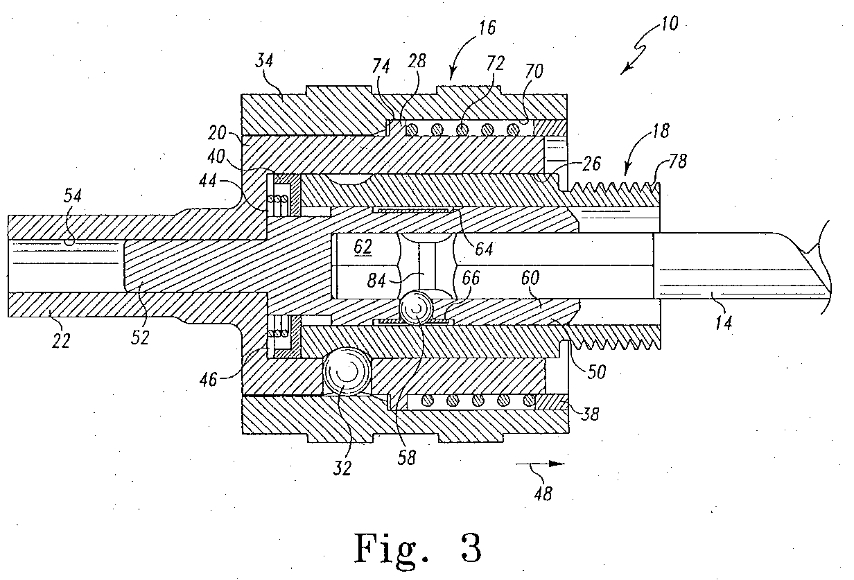
- Fig. 3 is a sectional view of the mandrel assembly of Fig. 1;
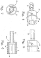
- Fig. 4 is a perspective view of the body of the mandrel assembly of Fig. 1;
- Fig. 5 is a side elevational view of the body of Fig. 4;
- Fig. 6 is a cross sectional view of the body of Fig. 4;
- Fig. 7 is a front elevational view of the body of Fig. 4;
- Fig. 8 is a side elevational view of the collar of the mandrel assembly of Fig. 1;
- Fig. 9 is a cross sectional view of the collar of the Fig. 8;
- Fig. 10 is a front elevational view of the annular sleeve of the mandrel assembly of Fig. 1;
- Fig. 11 is a side elevational view of the annular sleeve of Fig. 10;
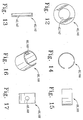
- Fig. 12 is a front elevational view of the ring-shaped platform of the mandrel assembly of Figs. 1 and 28;
- Fig. 13 is a cross sectional view of the ring-shaped platform of the Fig. 12;
- Fig. 14 is a front elevational view of the retaining band of the mandrel assembly of Figs. 1 and 28;
- Fig. 15 is a first side elevational view of the retaining band of Fig. 14;
- Fig. 16 is a perspective view of the retaining band of Fig. 14;
- Fig. 17 a second side elevational view of the retaining band of Fig. 14;
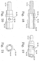
- Fig. 18 is a cross sectional view of the bit coupler of the mandrel assembly of Figs. 1 and 28;
- Fig. 19 is a perspective view of the bit coupler of Fig. 18;
- Fig. 20 is a side elevational view of the bit coupler of Fig. 18;
- Fig. 21 is a front elevational view of the bit coupler of Fig. 18;
- Fig. 22 is a side elevational view of the adapter of the mandrel assembly of Figs. 1 and 28;
- Fig. 23 is a cross sectional view of the adapter of Fig. 22;
- Fig. 24 is a rear elevational view of the adapter of Fig. 22;
- Fig. 25 is a perspective view of a hole saw which is usable with the mandrel assembly of Figs. 1 and 28;
- Fig. 26 is a side elevational view of a drill bit that is usable with the mandrel assembly of Figs. 1 and 28;
- Fig. 27 is an end elevational view of the pilot drill bit of Fig. 26;
- Fig. 28 is a sectional view of a second embodiment of a mandrel assembly that incorporates the features of the present invention therein;
- Fig. 29 is a perspective view of the mandrel assembly of Fig. 28;
- Fig. 30 is a cross sectional view of the body of the mandrel assembly of Fig. 28;
- Fig. 31 is a front elevational view of the body of Fig. 30;
- Fig. 32 is a side elevational view of the body of Fig. 30;
- Fig. 33 is a side elevational view of the collar of the mandrel assembly of Fig. 28;
- Fig. 34 is a cross sectional view of the collar of the Fig. 33;
- Fig. 35 is a front elevational view of the annular sleeve of the mandrel assembly of Fig. 28; and
- Fig. 36 is a side elevational view of the annular sleeve of Fig. 35.
-
- While the invention is susceptible to various modifications and alternative forms, specific embodiments thereof has been shown by way of example in the drawings and will herein be described in detail. It should be understood, however, that there is no intent to limit the invention to the particular forms disclosed, but on the contrary, the intention is to cover all modifications, equivalents, and alternatives falling within the spirit and scope of the invention as defined by the appended claims.
- Referring now to FIGS. 1-2, there is shown a first embodiment of a
mandrel assembly 10 which is adapted to attach ahole saw 12 and apilot drill bit 14 to an electric drill (not shown). Themandrel assembly 10 includes two main components, namely, abase mechanism 16 and anadapter 18. - As shown in FIGS 3-7, the
base mechanism 16 includes abody 20 having a hexagonally-shapedshank 22 which is configured to be received within a chuck of the electric drill (not shown). Thebody 20 includes acylindrical portion 24 which defines acavity 26. Thebody 20 is formed to include ashoulder 28 which extends outwardly from thecylindrical portion 24. Thecylindrical portion 24 has defined therein anopening 30 adapted to receive aball 32 as shown in FIG. 3. - The
base mechanism 16 further includes acollar 34 which is movable in relation to thebody 20. Thecollar 34 is positioned around thecylindrical portion 24 of thebody 20 as shown in FIG. 3. Thecollar 34 defines apassageway 36 extending therethrough as shown in Fig. 9. Anannular sleeve 38 is attached to thecollar 34 and positioned within thepassageway 36. - Additionally, the
base mechanism 16 includes a ring-shapedplatform 40 having a hole 42 defined therein (see FIGS. 12-13). Theplatform 40 is located in thecavity 26 of thebody 20 as shown in FIG. 3. Aspring 44 is interposed between theplatform 40 and aledge 46 of thebody 20. Thespring 44 functions to urge theplatform 40 in the direction ofarrow 48. - The
base mechanism 16 also includes abit coupler 50 positioned within thecavity 26 as shown in FIG. 3 (see also FIGS 18-21). Thebit coupler 50 has astem portion 52 which is received into arecess 54 defined within thehex shank 22. Thebit coupler 50 has defined therein an opening 56 adapted to receive aball 58 as shown in FIG. 3. Thebit coupler 50 further defines acavity 60 adapted to receive ahex end 62 of thedrill bit 14. Thebit coupler 50 further includes anexternal recess 64 which is defined in an outer surface of thebit coupler 50. A retainingband 66 is positioned within the external recess as shown in FIG. 3 (see also FIGS. 14-17). The retainingband 66 has a hole 68 defined therein which partially receives theball 58 therein as shown in FIG. 3. - When the
base mechanism 16 is assembled, aspring space 70 is defined between thecollar 34 and thebody 20. Aspring 72 is positioned in thespring space 70 and is contained therein by contact with theshoulder 28 and theannular sleeve 38. Thespring 72 functions to urge thecollar 34 in the direction ofarrow 48. Movement of thecollar 34 relative to thebody 20 is limited due to aninterior lip 74 of thecollar 34 contacting theshoulder 28 of thebody 20. - FIG. 3 shows the
adapter 18 coupled to thebase mechanism 16. Theadapter 18 has a passageway 76 extending therethrough (see also FIGS. 23 and 24). A set ofexternal threads 78 are provided on one end portion of the adapter 18 (see FIGS. 3 and 22-23). Theexternal threads 78 are configured to cooperate with a set ofinternal threads 80 defined in anopening 82 of the hole saw 12 (see FIG. 25) so as to attach the hole saw 12 to themandrel assembly 10. The exterior surface of theadapter 18 possesses a hexagonal shape while thecavity 26 defined by the interior surface of thebody 20 possesses a complementary hexagonal shape. As a result, rotation of thebody 20 causes rotational force to be transmitted to theadapter 18. In turn, rotation of theadapter 18 causes the hole saw 12 to rotate. - The
drill bit 14 is maintained in the passageway 76 of theadapter 18 due to the cooperation ofbit coupler 50 and theball 58. In particular, agroove 84 defined in thehex end 62 of thedrill bit 14 receives theball 58 so as to lock thedrill bit 14 in adapter 18 (and consequently in the mandrel assembly 10) as shown in FIG. 3. - The
adapter 18 has a groove 86 defined in a sidewall 88 thereof. Theadapter 18 is maintained in thecavity 26 of thebody 20 due to the cooperation of the groove 86 and theball 32. In particular, the groove 86 receives theball 32 so as to lock theadapter 18 in themandrel assembly 10 as shown in FIG. 3. - It should be appreciated from FIG. 1 that during use of the
mandrel assembly 10, thehex shank 22 is secured within the chuck of the electric drill (not shown). Further, thedrill bit 14 and thehole saw 12 are attached to themandrel assembly 10 as described above. - Referring now to FIGS. 28-29, there is shown a second embodiment of a
mandrel assembly 110 which is adapted to attach thehole saw 12 and thepilot drill bit 14 to an electric drill (not shown). Themandrel assembly 110 also includes two main components, namely, abase mechanism 116 and anadapter 118. - As shown in FIGS 28-32, the
base mechanism 116 includes abody 120 having a hexagonally-shapedshank 122 which is configured to be received within a chuck of the electric drill (not shown). Thebody 120 includes a substantiallycylindrical portion 124 which defines acavity 126. Thebody 120 is formed to include ashoulder 128 which extends outwardly from thecylindrical portion 124. Thecylindrical portion 124 has defined therein anopening 130 adapted to receive aball 132 as shown in FIG. 28. - The
base mechanism 116 further includes acollar 134 which is movable in relation to the body 120 (see FIGS. 28 and 33-34). Thecollar 134 is positioned around thecylindrical portion 124 of thebody 120 as shown in FIG. 28. Thecollar 134 defines apassageway 136 extending therethrough. Anannular sleeve 138 is attached to thecollar 134 and positioned within thepassageway 136. - Additionally, the
base mechanism 116 includes a ring-shapedplatform 140 having a hole 142 defined therein (see FIGS 12-13). Theplatform 140 is located in thecavity 126 of thebody 120 as shown in FIG. 29. Aspring 144 is interposed between theplatform 140 and aledge 146 of thebody 120. Thespring 144 functions to urge theplatform 140 in the direction ofarrow 148. - The
base mechanism 116 also includes abit coupler 150 positioned within thecavity 126 as shown in FIG. 28 (see also FIGS 18-21). Thebit coupler 150 has astem portion 152 which is received into arecess 154 defined within thehex shank 122. Thebit coupler 150 has defined therein an opening 156 adapted to receive aball 158 as shown in FIG. 28. Thebit coupler 150 further defines a cavity 160 adapted to receive ahex end 162 of thedrill bit 14. Thebit coupler 150 further includes an external recess 164 which is defined in an outer surface of thebit coupler 150. A retainingband 166 is positioned within the external recess as shown in FIG. 28 (see also FIGS. 14-17). The retainingband 166 has a hole 168 defined therein which partially receives theball 158 therein as shown in FIG. 28. - When the
base mechanism 116 is assembled, aspring space 170 is defined between thecollar 134 and thebody 120. Aspring 172 is positioned in thespring space 170 and is contained therein by contact with theshoulder 128 and theannular sleeve 138. Thespring 172 functions to urge thecollar 134 in the direction ofarrow 148. Movement of thecollar 134 relative to thebody 120 is limited due to aninterior lip 174 of thecollar 134 contacting theshoulder 128 of thebody 120. - FIG. 28 shows the
adapter 118 coupled to thebase mechanism 116. Theadapter 118 has a passageway 176 extending therethrough (see FIGS. 22-23). A set ofexternal threads 178 are provided on one end portion of the adapter 118 (see FIGS. 28 and 22-23). Theexternal threads 178 are configured to cooperate with a set ofinternal threads 80 defined in anopening 82 of the hole saw 12 (see FIG. 25) so as to attach the hole saw 12 to themandrel assembly 110. The exterior surface of theadapter 118 possesses a hexagonal shape while thecavity 126 defined by the interior surface of thebody 120 possesses a cylindrical shape as shown in Figs 30-31. - The
drill bit 14 is maintained in the passageway 176 of theadapter 118 due to the cooperation ofbit coupler 150 and theball 158. In particular, agroove 184 defined in thehex end 162 of thedrill bit 14 receives theball 158 so as to lock thedrill bit 14 in adapter 118 (and consequently in the mandrel assembly 110) as shown in FIG. 28. - The
adapter 118 has agroove 186 defined in a sidewall 188 thereof. Theadapter 118 is maintained in thecavity 126 of thebody 120 due to the cooperation of thegroove 186 and theball 132. In particular, thegroove 186 receives theball 132 so as to lock theadapter 118 in themandrel assembly 110 as shown in FIG. 28. - The
mandrel assembly 110 further includes a pair ofpins 190 which are respectively secured within a pair ofapertures 192 defined in thebody 120 as shown in FIG. 28. In order to attach the hole saw 12 to themandrel assembly 110, initially, theadapter 118 is coupled to thehole saw 12 by meshingly engaging theexternal threads 178 of theadapter 110 with theinternal threads 80 of the hole saw until theadapter 118 is secured to thehole saw 12. Then, theadapter 118 with thehole saw 12 attached thereto is advanced into thecavity 126 of thebody 120. Simultaneously, thecollar 134 is urged in the direction ofarrow 196 against the spring bias ofspring 172 thereby allowingball 132 to move away as the adapter pushes against theplatform 140. Once thegroove 186 is aligned with theball 132, a user may release thecollar 134 thereby allowing it to move in the direction ofarrow 148 due to the bias ofspring 172. Once theadapter 118 with thehole saw 12 attached thereto is advanced into thecavity 126 of thebody 120, the pair ofpins 190 are respectively positioned within a pair ofopenings 81 defined in the hole saw (see Fig. 25). As a result, rotation of thebody 120 causes rotational force to be transmitted to the pair ofpins 190. In turn, rotation of the pair ofpins 190 causes the hole saw 12 to rotate. - During use of the
mandrel assembly 110, thehex shank 122 is secured within the chuck of the electric drill (not shown). Further, thedrill bit 14 and thehole saw 12 are attached to themandrel assembly 110 as described above. - It should be appreciated that in both embodiments the
drill bit 14 may be removed from thebit coupler adapter cavity body adapter cavity drill bit 14 is locked in place because the inner wall of theadapter ball groove drill bit 14. - While the invention has been illustrated and described in detail in the drawings and foregoing description, the same is to be considered as illustrative and not restrictive in character, it being understood that only the preferred embodiments have been shown and described and that all changes and modifications that come within the spirit of the invention are desired to be protected.
- There is a plurality of advantages of the present invention arising from the various features of the mandrel assembly described herein. It will be noted that alternative embodiments of the mandrel assembly of the present invention may not include all of the features described yet still benefit from at least some of the advantages of such features. Those of ordinary skill in the art may readily devise their own implementations of the mandrel assembly that incorporate one or more of the features of the present invention and fall within the spirit and scope of the present invention as defined by the appended claims.
Claims (16)
- A mandrel assembly (10) for use with a hole saw (12) and a drill bit (14), comprising:a body (20) having (i) a shank portion (22) configured to be received in a chuck of a drill, and (ii) an adapter receiving portion (24) that includes a detent hole (30) extending through a wall thereof and further that defines an adapter receiving cavity (26);an adapter (18) having a first portion configured to be received within said adapter receiving cavity (26), said first portion having a detent groove (86) defined therein, and (i) a second portion having a first coupling (78) configured to releasably couple to a second coupling (80) of said hole saw (12); anda detent (32) located within said detent hole (30) of said body (20) and configured to be received within said detent groove (86) of said adapter (18).
- The mandrel assembly of claim 1, wherein said first coupling (78) includes a first threaded segment (78) configured to threadingly engage a second threaded segment (80) of said hole saw (12).
- The mandrel assembly of claim 2, wherein:said adapter (18) has a first end and a second end, andsaid adapter (18) includes a passage (76) that extends from said first end to said second end.
- The mandrel assembly of claim 3, wherein said passage (76) is configured to receive said drill bit (14) therein.
- The mandrel assembly of claim 2, wherein said first threaded segment (78) is an externally threaded segment.
- The mandrel assembly of claim 2, wherein:said wall of said adapter receiving portion (24) of said body (20) includes an inner surface and an outer surface, andsaid detent hole (30) extends from said inner surface to said outer surface.
- The mandrel assembly of claim 2, further comprising a collar (34) positioned around said body (20), wherein:said collar (34) is movable between a lock position and a release position,said collar (34) is positioned to contact said detent (32) so as to maintain said detent (32) within said detent groove (86) of said adapter (18) when said collar (34) is positioned in said lock position; andsaid collar (34) is positioned to allow said detent (32) to move out of said detent groove (86) of said adapter (18) when said collar (34) is positioned in said release position.
- The mandrel assembly of claim 7, further comprising a spring (72) configured to bias said collar 34 into said lock position.
- The mandrel assembly of claim 2, wherein said detent (32) is a ball detent.
- The mandrel assembly of claim 2, wherein said first portion of said adapter (18) further has a polygonally-shaped exterior surface.
- The mandrel assembly of claim 10, wherein said polygonally-shaped exterior surface is a hexagonally-shaped exterior surface.
- The mandrel assembly of claim 10, wherein said adapter receiving portion (24) of said body (20) possesses a polygonally-shaped interior surface configured to mate with said polygonally-shaped exterior surface of said adapter (18).
- The mandrel assembly of claim 12, wherein said polygonally-shaped interior surface of said adapter receiving portion (24) is a hexagonally-shaped interior surface.
- The mandrel assembly of claim 10, wherein said detent groove (86) is spaced apart from said polygonally-shaped exterior surface.
- The mandrel assembly of claim 14, wherein both said detent groove 86 and said polygonally-shaped exterior surface is located within said adapter receiving cavity (26) when said adapter (18) is coupled to said body (20).
- The mandrel assembly of claim 15, wherein said first threaded segment (78) is located outside of said adapter receiving cavity (26) when said adapter (18) is coupled to said body (20).
Applications Claiming Priority (3)
| Application Number | Priority Date | Filing Date | Title |
|---|---|---|---|
| US23052600P | 2000-09-01 | 2000-09-01 | |
| US230526P | 2000-09-01 | ||
| EP01203274A EP1193014B1 (en) | 2000-09-01 | 2001-08-30 | Mandrel assembly for hole saw and drill bit |
Related Parent Applications (1)
| Application Number | Title | Priority Date | Filing Date |
|---|---|---|---|
| EP01203274A Division EP1193014B1 (en) | 2000-09-01 | 2001-08-30 | Mandrel assembly for hole saw and drill bit |
Publications (2)
| Publication Number | Publication Date |
|---|---|
| EP1462198A1 true EP1462198A1 (en) | 2004-09-29 |
| EP1462198B1 EP1462198B1 (en) | 2007-10-24 |
Family
ID=32826549
Family Applications (1)
| Application Number | Title | Priority Date | Filing Date |
|---|---|---|---|
| EP04014071A Expired - Lifetime EP1462198B1 (en) | 2000-09-01 | 2001-08-30 | Quick change mandrel assembly for hole saw and drill bit |
Country Status (1)
| Country | Link |
|---|---|
| EP (1) | EP1462198B1 (en) |
Cited By (7)
| Publication number | Priority date | Publication date | Assignee | Title |
|---|---|---|---|---|
| US8038372B2 (en) | 2007-04-13 | 2011-10-18 | Black & Decker Inc. | Push button holesaw mandrel assembly |
| US8038371B2 (en) | 2007-04-13 | 2011-10-18 | Black & Decker Inc. | Push button holesaw mandrel assembly |
| CN103624500A (en) * | 2013-12-13 | 2014-03-12 | 哈尔滨电气动力装备有限公司 | Deep hole machining process for rotor shaft of motor |
| US9707626B2 (en) * | 2014-10-22 | 2017-07-18 | Rote Mate Industry Co., Ltd. | Hole saw assembly |
| WO2017211554A1 (en) * | 2016-06-06 | 2017-12-14 | Robert Bosch Gmbh | Quick release adapter |
| FR3116879A1 (en) * | 2020-11-27 | 2022-06-03 | Comap | Coupling member, device and method for connection through a partition |
| US20250162045A1 (en) * | 2022-02-25 | 2025-05-22 | Bordo International Pty. Ltd. | Quick change hole saw mandrel |
Citations (2)
| Publication number | Priority date | Publication date | Assignee | Title |
|---|---|---|---|---|
| US3251605A (en) * | 1963-09-26 | 1966-05-17 | Supreme Products Corp | Quick release chuck |
| US5246317A (en) * | 1991-12-31 | 1993-09-21 | American Saw & Mfg. Company | Quick-release arbor for hole saws |
-
2001
- 2001-08-30 EP EP04014071A patent/EP1462198B1/en not_active Expired - Lifetime
Patent Citations (2)
| Publication number | Priority date | Publication date | Assignee | Title |
|---|---|---|---|---|
| US3251605A (en) * | 1963-09-26 | 1966-05-17 | Supreme Products Corp | Quick release chuck |
| US5246317A (en) * | 1991-12-31 | 1993-09-21 | American Saw & Mfg. Company | Quick-release arbor for hole saws |
Cited By (8)
| Publication number | Priority date | Publication date | Assignee | Title |
|---|---|---|---|---|
| US8038372B2 (en) | 2007-04-13 | 2011-10-18 | Black & Decker Inc. | Push button holesaw mandrel assembly |
| US8038371B2 (en) | 2007-04-13 | 2011-10-18 | Black & Decker Inc. | Push button holesaw mandrel assembly |
| CN103624500A (en) * | 2013-12-13 | 2014-03-12 | 哈尔滨电气动力装备有限公司 | Deep hole machining process for rotor shaft of motor |
| CN103624500B (en) * | 2013-12-13 | 2015-12-30 | 哈尔滨电气动力装备有限公司 | Rotor axis of electric deep hole processing technology |
| US9707626B2 (en) * | 2014-10-22 | 2017-07-18 | Rote Mate Industry Co., Ltd. | Hole saw assembly |
| WO2017211554A1 (en) * | 2016-06-06 | 2017-12-14 | Robert Bosch Gmbh | Quick release adapter |
| FR3116879A1 (en) * | 2020-11-27 | 2022-06-03 | Comap | Coupling member, device and method for connection through a partition |
| US20250162045A1 (en) * | 2022-02-25 | 2025-05-22 | Bordo International Pty. Ltd. | Quick change hole saw mandrel |
Also Published As
| Publication number | Publication date |
|---|---|
| EP1462198B1 (en) | 2007-10-24 |
Similar Documents
| Publication | Publication Date | Title |
|---|---|---|
| US6623220B2 (en) | Quick change mandrel assembly for use with a hole saw and a pilot drill bit | |
| US6543959B1 (en) | Two-way quick connector | |
| US6254303B1 (en) | Quick-release connector and methods therefore | |
| US11724370B2 (en) | Lockable drive socket adapter | |
| CA2457241C (en) | Universal quick change hole saw arbor | |
| US6929266B2 (en) | Bit holder | |
| US5813296A (en) | Quick release socket mechanism | |
| US4874181A (en) | Coupling member for securing a drilling head to the rotatable rod of a pneumatic tool body | |
| US5090275A (en) | Retainer apparatus for a wrench unit | |
| US20030057661A1 (en) | Power drivable chuck | |
| US4378053A (en) | Tool holder | |
| EP1132175A3 (en) | Adjustable spindle lock | |
| US20040126182A1 (en) | Connector | |
| EP2979790B1 (en) | Tool bit holder for power tool | |
| US5851093A (en) | Coupling system for machine tools | |
| EP1462198B1 (en) | Quick change mandrel assembly for hole saw and drill bit | |
| EP0691184B1 (en) | Collet type fastener removal tool | |
| US5657741A (en) | Quick release coupling for archery bow stabilizer | |
| CA2216846A1 (en) | Counter centrifugal chuck and mounting systems | |
| EP1526009A1 (en) | Ball hitch for an implement drawbar of an agricultural vehicle. | |
| EP1457291B1 (en) | Connection of tool handle with tool bit | |
| EP1457292A1 (en) | Tool bit/handle connector | |
| US20040104545A1 (en) | Connection of tool with tool bit | |
| EP1260297B1 (en) | Core body lock device of core drill and core body used for the device | |
| CA2510287A1 (en) | Method of securing a rotary cutter to a body of a down hole tool and a rotary cutter assembly |
Legal Events
| Date | Code | Title | Description |
|---|---|---|---|
| PUAI | Public reference made under article 153(3) epc to a published international application that has entered the european phase |
Free format text: ORIGINAL CODE: 0009012 |
|
| AC | Divisional application: reference to earlier application |
Ref document number: 1193014 Country of ref document: EP Kind code of ref document: P |
|
| AK | Designated contracting states |
Kind code of ref document: A1 Designated state(s): AT BE CH CY DE DK ES FI FR GB GR IE IT LI LU MC NL PT SE TR |
|
| 17P | Request for examination filed |
Effective date: 20050329 |
|
| AKX | Designation fees paid |
Designated state(s): AT BE CH CY DE DK ES FI FR GB GR IE IT LI LU MC NL PT SE TR |
|
| 17Q | First examination report despatched |
Effective date: 20051117 |
|
| GRAP | Despatch of communication of intention to grant a patent |
Free format text: ORIGINAL CODE: EPIDOSNIGR1 |
|
| GRAS | Grant fee paid |
Free format text: ORIGINAL CODE: EPIDOSNIGR3 |
|
| GRAA | (expected) grant |
Free format text: ORIGINAL CODE: 0009210 |
|
| AC | Divisional application: reference to earlier application |
Ref document number: 1193014 Country of ref document: EP Kind code of ref document: P |
|
| AK | Designated contracting states |
Kind code of ref document: B1 Designated state(s): AT BE CH CY DE DK ES FI FR GB GR IE IT LI LU MC NL PT SE TR |
|
| REG | Reference to a national code |
Ref country code: GB Ref legal event code: FG4D |
|
| REG | Reference to a national code |
Ref country code: CH Ref legal event code: EP |
|
| REG | Reference to a national code |
Ref country code: IE Ref legal event code: FG4D |
|
| REF | Corresponds to: |
Ref document number: 60131108 Country of ref document: DE Date of ref document: 20071206 Kind code of ref document: P |
|
| NLV1 | Nl: lapsed or annulled due to failure to fulfill the requirements of art. 29p and 29m of the patents act | ||
| REG | Reference to a national code |
Ref country code: ES Ref legal event code: FG2A Ref document number: 2294398 Country of ref document: ES Kind code of ref document: T3 |
|
| PG25 | Lapsed in a contracting state [announced via postgrant information from national office to epo] |
Ref country code: NL Free format text: LAPSE BECAUSE OF FAILURE TO SUBMIT A TRANSLATION OF THE DESCRIPTION OR TO PAY THE FEE WITHIN THE PRESCRIBED TIME-LIMIT Effective date: 20071024 Ref country code: SE Free format text: LAPSE BECAUSE OF FAILURE TO SUBMIT A TRANSLATION OF THE DESCRIPTION OR TO PAY THE FEE WITHIN THE PRESCRIBED TIME-LIMIT Effective date: 20080124 Ref country code: LI Free format text: LAPSE BECAUSE OF FAILURE TO SUBMIT A TRANSLATION OF THE DESCRIPTION OR TO PAY THE FEE WITHIN THE PRESCRIBED TIME-LIMIT Effective date: 20071024 Ref country code: CH Free format text: LAPSE BECAUSE OF FAILURE TO SUBMIT A TRANSLATION OF THE DESCRIPTION OR TO PAY THE FEE WITHIN THE PRESCRIBED TIME-LIMIT Effective date: 20071024 |
|
| REG | Reference to a national code |
Ref country code: CH Ref legal event code: PL |
|
| PG25 | Lapsed in a contracting state [announced via postgrant information from national office to epo] |
Ref country code: PT Free format text: LAPSE BECAUSE OF FAILURE TO SUBMIT A TRANSLATION OF THE DESCRIPTION OR TO PAY THE FEE WITHIN THE PRESCRIBED TIME-LIMIT Effective date: 20080324 |
|
| PG25 | Lapsed in a contracting state [announced via postgrant information from national office to epo] |
Ref country code: AT Free format text: LAPSE BECAUSE OF FAILURE TO SUBMIT A TRANSLATION OF THE DESCRIPTION OR TO PAY THE FEE WITHIN THE PRESCRIBED TIME-LIMIT Effective date: 20071024 |
|
| ET | Fr: translation filed | ||
| PG25 | Lapsed in a contracting state [announced via postgrant information from national office to epo] |
Ref country code: DK Free format text: LAPSE BECAUSE OF FAILURE TO SUBMIT A TRANSLATION OF THE DESCRIPTION OR TO PAY THE FEE WITHIN THE PRESCRIBED TIME-LIMIT Effective date: 20071024 |
|
| PG25 | Lapsed in a contracting state [announced via postgrant information from national office to epo] |
Ref country code: BE Free format text: LAPSE BECAUSE OF FAILURE TO SUBMIT A TRANSLATION OF THE DESCRIPTION OR TO PAY THE FEE WITHIN THE PRESCRIBED TIME-LIMIT Effective date: 20071024 |
|
| PLBE | No opposition filed within time limit |
Free format text: ORIGINAL CODE: 0009261 |
|
| STAA | Information on the status of an ep patent application or granted ep patent |
Free format text: STATUS: NO OPPOSITION FILED WITHIN TIME LIMIT |
|
| 26N | No opposition filed |
Effective date: 20080725 |
|
| PG25 | Lapsed in a contracting state [announced via postgrant information from national office to epo] |
Ref country code: GR Free format text: LAPSE BECAUSE OF FAILURE TO SUBMIT A TRANSLATION OF THE DESCRIPTION OR TO PAY THE FEE WITHIN THE PRESCRIBED TIME-LIMIT Effective date: 20080125 |
|
| PG25 | Lapsed in a contracting state [announced via postgrant information from national office to epo] |
Ref country code: FI Free format text: LAPSE BECAUSE OF FAILURE TO SUBMIT A TRANSLATION OF THE DESCRIPTION OR TO PAY THE FEE WITHIN THE PRESCRIBED TIME-LIMIT Effective date: 20071024 |
|
| PG25 | Lapsed in a contracting state [announced via postgrant information from national office to epo] |
Ref country code: MC Free format text: LAPSE BECAUSE OF NON-PAYMENT OF DUE FEES Effective date: 20080831 |
|
| PG25 | Lapsed in a contracting state [announced via postgrant information from national office to epo] |
Ref country code: CY Free format text: LAPSE BECAUSE OF FAILURE TO SUBMIT A TRANSLATION OF THE DESCRIPTION OR TO PAY THE FEE WITHIN THE PRESCRIBED TIME-LIMIT Effective date: 20071024 Ref country code: IE Free format text: LAPSE BECAUSE OF NON-PAYMENT OF DUE FEES Effective date: 20080901 |
|
| PG25 | Lapsed in a contracting state [announced via postgrant information from national office to epo] |
Ref country code: LU Free format text: LAPSE BECAUSE OF NON-PAYMENT OF DUE FEES Effective date: 20080830 |
|
| PG25 | Lapsed in a contracting state [announced via postgrant information from national office to epo] |
Ref country code: TR Free format text: LAPSE BECAUSE OF FAILURE TO SUBMIT A TRANSLATION OF THE DESCRIPTION OR TO PAY THE FEE WITHIN THE PRESCRIBED TIME-LIMIT Effective date: 20071024 |
|
| REG | Reference to a national code |
Ref country code: FR Ref legal event code: PLFP Year of fee payment: 16 |
|
| REG | Reference to a national code |
Ref country code: FR Ref legal event code: PLFP Year of fee payment: 17 |
|
| REG | Reference to a national code |
Ref country code: FR Ref legal event code: PLFP Year of fee payment: 18 |
|
| PGFP | Annual fee paid to national office [announced via postgrant information from national office to epo] |
Ref country code: ES Payment date: 20190919 Year of fee payment: 19 Ref country code: IT Payment date: 20190821 Year of fee payment: 19 Ref country code: FR Payment date: 20190822 Year of fee payment: 19 |
|
| PGFP | Annual fee paid to national office [announced via postgrant information from national office to epo] |
Ref country code: GB Payment date: 20190827 Year of fee payment: 19 |
|
| PGFP | Annual fee paid to national office [announced via postgrant information from national office to epo] |
Ref country code: DE Payment date: 20191021 Year of fee payment: 19 |
|
| REG | Reference to a national code |
Ref country code: DE Ref legal event code: R119 Ref document number: 60131108 Country of ref document: DE |
|
| GBPC | Gb: european patent ceased through non-payment of renewal fee |
Effective date: 20200830 |
|
| PG25 | Lapsed in a contracting state [announced via postgrant information from national office to epo] |
Ref country code: DE Free format text: LAPSE BECAUSE OF NON-PAYMENT OF DUE FEES Effective date: 20210302 Ref country code: FR Free format text: LAPSE BECAUSE OF NON-PAYMENT OF DUE FEES Effective date: 20200831 |
|
| PG25 | Lapsed in a contracting state [announced via postgrant information from national office to epo] |
Ref country code: GB Free format text: LAPSE BECAUSE OF NON-PAYMENT OF DUE FEES Effective date: 20200830 |
|
| REG | Reference to a national code |
Ref country code: ES Ref legal event code: FD2A Effective date: 20211229 |
|
| PG25 | Lapsed in a contracting state [announced via postgrant information from national office to epo] |
Ref country code: ES Free format text: LAPSE BECAUSE OF NON-PAYMENT OF DUE FEES Effective date: 20200831 |
|
| PG25 | Lapsed in a contracting state [announced via postgrant information from national office to epo] |
Ref country code: IT Free format text: LAPSE BECAUSE OF NON-PAYMENT OF DUE FEES Effective date: 20200830 |