EP1460781A1 - Optical filter, interleaver, and optical communication system - Google Patents
Optical filter, interleaver, and optical communication system Download PDFInfo
- Publication number
- EP1460781A1 EP1460781A1 EP02783811A EP02783811A EP1460781A1 EP 1460781 A1 EP1460781 A1 EP 1460781A1 EP 02783811 A EP02783811 A EP 02783811A EP 02783811 A EP02783811 A EP 02783811A EP 1460781 A1 EP1460781 A1 EP 1460781A1
- Authority
- EP
- European Patent Office
- Prior art keywords
- beam splitter
- light
- optical
- optical path
- outputs
- Prior art date
- Legal status (The legal status is an assumption and is not a legal conclusion. Google has not performed a legal analysis and makes no representation as to the accuracy of the status listed.)
- Withdrawn
Links
Images




Classifications
-
- H—ELECTRICITY
- H04—ELECTRIC COMMUNICATION TECHNIQUE
- H04B—TRANSMISSION
- H04B10/00—Transmission systems employing electromagnetic waves other than radio-waves, e.g. infrared, visible or ultraviolet light, or employing corpuscular radiation, e.g. quantum communication
-
- G—PHYSICS
- G02—OPTICS
- G02B—OPTICAL ELEMENTS, SYSTEMS OR APPARATUS
- G02B6/00—Light guides; Structural details of arrangements comprising light guides and other optical elements, e.g. couplings
- G02B6/24—Coupling light guides
- G02B6/26—Optical coupling means
- G02B6/28—Optical coupling means having data bus means, i.e. plural waveguides interconnected and providing an inherently bidirectional system by mixing and splitting signals
- G02B6/293—Optical coupling means having data bus means, i.e. plural waveguides interconnected and providing an inherently bidirectional system by mixing and splitting signals with wavelength selective means
- G02B6/29346—Optical coupling means having data bus means, i.e. plural waveguides interconnected and providing an inherently bidirectional system by mixing and splitting signals with wavelength selective means operating by wave or beam interference
- G02B6/29349—Michelson or Michelson/Gires-Tournois configuration, i.e. based on splitting and interferometrically combining relatively delayed signals at a single beamsplitter
-
- G—PHYSICS
- G02—OPTICS
- G02B—OPTICAL ELEMENTS, SYSTEMS OR APPARATUS
- G02B26/00—Optical devices or arrangements for the control of light using movable or deformable optical elements
- G02B26/02—Optical devices or arrangements for the control of light using movable or deformable optical elements for controlling the intensity of light
-
- G—PHYSICS
- G02—OPTICS
- G02B—OPTICAL ELEMENTS, SYSTEMS OR APPARATUS
- G02B27/00—Optical systems or apparatus not provided for by any of the groups G02B1/00 - G02B26/00, G02B30/00
- G02B27/10—Beam splitting or combining systems
- G02B27/14—Beam splitting or combining systems operating by reflection only
- G02B27/145—Beam splitting or combining systems operating by reflection only having sequential partially reflecting surfaces
-
- G—PHYSICS
- G02—OPTICS
- G02B—OPTICAL ELEMENTS, SYSTEMS OR APPARATUS
- G02B5/00—Optical elements other than lenses
- G02B5/04—Prisms
-
- G—PHYSICS
- G02—OPTICS
- G02B—OPTICAL ELEMENTS, SYSTEMS OR APPARATUS
- G02B6/00—Light guides; Structural details of arrangements comprising light guides and other optical elements, e.g. couplings
- G02B6/24—Coupling light guides
- G02B6/26—Optical coupling means
- G02B6/28—Optical coupling means having data bus means, i.e. plural waveguides interconnected and providing an inherently bidirectional system by mixing and splitting signals
-
- G—PHYSICS
- G02—OPTICS
- G02B—OPTICAL ELEMENTS, SYSTEMS OR APPARATUS
- G02B6/00—Light guides; Structural details of arrangements comprising light guides and other optical elements, e.g. couplings
- G02B6/24—Coupling light guides
- G02B6/26—Optical coupling means
- G02B6/28—Optical coupling means having data bus means, i.e. plural waveguides interconnected and providing an inherently bidirectional system by mixing and splitting signals
- G02B6/293—Optical coupling means having data bus means, i.e. plural waveguides interconnected and providing an inherently bidirectional system by mixing and splitting signals with wavelength selective means
- G02B6/29379—Optical coupling means having data bus means, i.e. plural waveguides interconnected and providing an inherently bidirectional system by mixing and splitting signals with wavelength selective means characterised by the function or use of the complete device
- G02B6/2938—Optical coupling means having data bus means, i.e. plural waveguides interconnected and providing an inherently bidirectional system by mixing and splitting signals with wavelength selective means characterised by the function or use of the complete device for multiplexing or demultiplexing, i.e. combining or separating wavelengths, e.g. 1xN, NxM
- G02B6/29386—Interleaving or deinterleaving, i.e. separating or mixing subsets of optical signals, e.g. combining even and odd channels into a single optical signal
-
- H—ELECTRICITY
- H04—ELECTRIC COMMUNICATION TECHNIQUE
- H04B—TRANSMISSION
- H04B10/00—Transmission systems employing electromagnetic waves other than radio-waves, e.g. infrared, visible or ultraviolet light, or employing corpuscular radiation, e.g. quantum communication
- H04B10/25—Arrangements specific to fibre transmission
Definitions
- the present invention relates to an optical filter, an interleaver including an optical filter, and an optical communication system having an optical filter or interleaver.
- An interleaver used in an optical communication system is designed to receive signal light of multiple wavelengths ( ⁇ 1 , ⁇ 2 ,..., ⁇ 2n-1 , ⁇ 2n ,%) and demultiplex the light into signal light in a first wavelength range ⁇ 1 ( ⁇ 1 , ⁇ 3 ,..., ⁇ 2n-1 ,...) and signal light in a second wavelength range ⁇ 2 ( ⁇ 2 , ⁇ 4 ,..., ⁇ 2n ,...), and is provided for a repeater or the like in the optical communication system.
- Such interleavers based on various schemes have been proposed.
- known interleavers include one that includes a polarizing/separating element, wavelength filter, and polarizing/combining element and one that includes an optical system forming a Mach-Zehnder interferometer.
- An interleaver having an optical filter including an optical system forming a Michelson interferometer is also conceivable.
- each transmission peak characteristic becomes a Gaussian type.
- the isolation of the optical filter including the optical system forming the Michelson interferometer is inevitably determined.
- the isolation between adjacent wavelengths is 9.8 dB, which is lower than that of an optical filter used for general optical communication, i.e., 20 dB.
- the isolation of the interleaver having the optical filter including the optical system forming the Michelson interferometer also becomes low, and hence the transmission quality of signal light in the wavelength division multiplexing optical communication system having this interleaver is poor.
- the present invention has been made to solve the above problems, and has as its object to provide an optical filter with excellent isolation, an interleaver including the optical filter, and an optical communication system including the optical filter or interleaver.
- An optical filter according to the present invention is characterized by comprising a first optical system which has a first beam splitter, splits light arriving at the first beam splitter through a first optical path into two light beams, and outputs the split light beams to different second and third optical paths, respectively, and a second optical system which outputs light arriving after being output from the first beam splitter to the second optical path upon giving the light an intensity change with wavelength dependence and a phase change.
- the optical filter comprises a reflecting mirror which outputs, to the first beam splitter, light arriving after being output from the first beam splitter to the third optical path, the second optical system outputs light given an intensity change with wavelength dependence and a phase change to the first beam splitter, and the first beam splitter splits light arriving after being output from the second optical system into two light beams, outputs the light beams to the first optical path and a fourth optical path, respectively, also splits light arriving after being output from the reflecting mirror into two light beams, and outputs the light beams to the first and fourth optical paths, respectively.
- the second optical system comprises a second beam splitter different from the first beam splitter and first and second reflecting mirrors, splits light arriving through the second optical path into two light beams using the second beam splitter, outputs the light beams to the first and second reflecting mirrors, respectively, splits the light reflected by the first reflecting mirror and arriving at the second beam splitter into two light beams, outputs one light beam to the first beam splitter, splits the light reflected by the second reflecting mirror and arriving at the second beam splitter into two light beams, and outputs one light beam to the first beam splitter.
- d2 be a length of the second optical path between the first beam splitter and the second beam splitter
- d3 be a length of the optical path between the first beam splitter and the reflecting mirror
- d5 be a length of the fifth optical path between the second beam splitter and the first reflecting mirror
- d6 be a length of the sixth optical path between the second beam splitter and the second reflecting mirror
- a free spectral range determined on the basis of a difference between the optical path lengths d5 and d6 is set to 1/2 a free spectral range determined on the basis of a difference between the optical path lengths d2 and d3.
- the split ratio of each of the first and second beam splitters is preferably 48% to 52%.
- the above optical filter preferably comprises a third optical system which outputs light arriving after being output from the first beam splitter to the third optical path, upon giving the light an intensity change with wavelength dependence and a phase change.
- the second optical system outputs light given an intensity change with wavelength dependence and a phase change to the first beam splitter
- the third optical system outputs light given an intensity change with wavelength dependence and a phase change to the first beam splitter
- the first beam splitter splits the light arriving after being output from the second optical system into two light beams, outputs the light beams to the first optical path and a fourth optical path, respectively, splits the light arriving after being output from the third optical system into two light beams, and outputs the light beams to the first and fourth optical paths, respectively.
- the second optical system comprises a second beam splitter different from the first beam splitter and first and second reflecting mirrors, splits light arriving at the second beam splitter through the second optical path into two light beams, outputs the light beams to the first and second reflecting mirrors, respectively, splits the light reflected by the first reflecting mirror and arriving at the second beam splitter into two light beams, outputs one light beam to the first beam splitter, splits the light reflected by the second reflecting mirror and arriving at the second beam splitter into two light beams, and outputs one light beam to the first beam splitter
- the third optical system comprises a third beam splitter different from the first beam splitter and third and fourth reflecting mirrors, splits light arriving at the third beam splitter through the third optical path into two light beams, outputs the light beams to the third and fourth reflecting mirrors, respectively, splits the light reflected by the third reflecting mirror and arriving at the third beam splitter into two light beams, outputs one light beam to the first beam splitter, splits the light reflected by the fourth reflecting mirrors,
- d2 be a length of the second optical path between the first beam splitter and the second beam splitter
- d3 be a length of the optical path between the first beam splitter and the third beam splitter
- d5 be a length of the fifth optical path between the second beam splitter and the first reflecting mirror
- d6 be a length of the sixth optical path between the second beam splitter and the second reflecting mirror
- d7 be a length of the seventh optical path between the third beam splitter and the third reflecting mirror
- d8 be a length of the eighth optical path between the third beam splitter and the fourth reflecting mirror
- a free spectral range determined on the basis of a difference between the optical path lengths d5 and d6 and a free spectral range determined on the basis of a difference between the optical path lengths d7 and d8 each are set to 1/2 a free spectral range determined 'on the basis of a difference between the optical path lengths d2 and d3.
- the second optical system comprises a second beam splitter different from the first beam splitter, a first reflecting mirror, and a first etalon filter, splits light arriving at the second beam splitter through the second optical path into two light beams, outputs the light beams to the first reflecting mirror and the first etalon filter, respectively, splits the light reflected by the first reflecting mirror and arriving at the second beam splitter into two light beams, outputs one light beam to the first beam splitter, splits the light reflected by the first etalon filter and arriving at the second beam splitter into two light beams, and outputs one light beam to the first beam splitter
- the third optical system comprises a third beam splitter different from the first beam splitter, a second reflecting mirror, and a second etalon filter, splits light arriving at the third beam splitter through the third optical path into two light beams, outputs the light beams to the second reflecting mirror and the second etalon filter, respectively, splits the light reflected by the second reflecting mirror and arriving at the third
- a free spectral range of each of the first and second etalon filters is set to 1/2 a free spectral range determined on the basis of a difference between the optical path lengths d2 and d3.
- the split ratio of the first beam splitter is 48% to 52%, and a split ratio of each of the second and third beam splitters is 24.9% to 28.9%.
- the first optical system further comprises a first reflecting mirror and a first etalon filter, splits light arriving at the first beam splitter through the first optical path into two light beams, outputs the light beams to the first reflecting mirror and the first etalon filter, respectively, splits light reflected by the first reflecting mirror and arriving at the first beam splitter into two light beams, outputs the light beams to the second and third optical paths, splits light reflected by the first etalon filter and arriving at the first beam splitter into two light beams, and outputs the light beams to the second and third optical paths, respectively
- the second optical system comprises a second optical beam splitter different from the first beam splitter, a second reflecting mirror, and a second etalon filter, splits light arriving at the second optical beam splitter through the second optical path into two light beams, outputs the light beams to the second reflecting mirror and the second etalon filter, splits light reflected by the second reflecting mirror and arriving at the second optical beam splitter into two light beams, outputs
- a free spectral range of each of the second and third etalon filters is set to 1/2 a free spectral range determined on the basis of a difference between the optical path length d2 and the optical path length d3.
- the isolation of the above optical filter is preferably not less than 15 dB.
- the wavelength dispersion of the above optical filter is preferably -5 ps/nm to 5 ps/nm.
- An interleaver is characterized by comprising an optical circulator which has a first terminal, a second terminal, and a third terminal, outputs, from the second terminal, light input to the first terminal, and outputs, from the third terminal, light input to the second terminal, and any one of the above optical filters in which the first optical path is connected to the second terminal of the optical circulator.
- An optical communication system is an optical communication system which transmits signal light of multiple wavelengths, characterized by including the above optical filter, the optical filter selecting and transmitting signal light of the signal light of the multiple wavelengths.
- Another optical communication system is an optical communication system which transmits signal light of multiple wavelengths, characterized by including the above interleaver, the interleaver demultiplexing the signal light of the multiple wavelengths.
- FIG. 1 is view showing the arrangement of an optical filter 200 of the first embodiment.
- the optical filter 200 has a first optical system 11, second optical system 21, and third optical system 31.
- the first optical system 11 includes a first beam splitter 211.
- the second optical system 21 includes a second beam splitter 221, first reflecting mirror (total reflection mirror) 222, and second reflecting mirror (total reflection mirror) 223.
- the third optical system 31 includes a third reflecting mirror (total reflection mirror) 232.
- the first beam splitter 211 splits light arriving through a first optical path P1 into two light beams and outputs one light beam to a second optical path P2 and the other light beam to a third optical path P3.
- the first beam splitter 211 splits the light arriving through the second optical path P2 into two light beams and outputs one light beam to the first optical path P1 and the other light beam to a fourth optical path P4.
- the first beam splitter 211 also splits the light arriving from the third optical path P3 into two light beams and outputs one light beam to the first optical path P1 and the other light beam to the fourth optical path P4.
- the second optical system 21 including the second beam splitter 221, first reflecting mirror 222, and second reflecting mirror 223 forms a Michelson interferometer. That is, the second beam splitter 221 splits light arriving through the second optical path P2 into two light beams and outputs one light beam to a fifth optical path P5 and the other light beam to a sixth optical path P6. The second beam splitter 221 splits the light arriving through the fifth optical path P5 into two light beams and outputs one light beam to the second optical path P2. The second beam splitter 221 also splits the light arriving through the sixth optical path P6 into two light beams and outputs one light beam to the second optical path P2. The second optical system 21 outputs light, output from the first beam splitter 211 to the second optical path P2 and arriving at the second optical system 21, after giving the light an intensity change with wavelength dependence and a phase change.
- the first reflecting mirror 222 reflects the light arriving through the fifth optical path P5 and outputs the light to the fifth optical path P5.
- the second reflecting mirror 223 reflects the light arriving through the sixth optical path P6 and outputs the light to the sixth optical path P6.
- the third reflecting mirror 232 of the third optical system 31 reflects the light arriving through the third optical path P3 and outputs the light to the third optical path P3.
- d2 be the length of the second optical path P2 between the first beam splitter 211 and the second beam splitter 221
- d3 be the length of the third optical path P3 between the first beam splitter 211 and the third reflecting mirror 232
- d5 be the length of the fifth optical path P5 between the second beam splitter 221 and the first reflecting mirror 222
- d6 be the length of the sixth optical path P6 between the second beam splitter 221 and the second reflecting mirror 223
- the free spectral range (FSR) determined on the basis of the difference between the optical path lengths d5 and d6 is set to 1/2 the free spectral range determined on the basis of the difference between the optical path lengths d2 and d3.
- the optical filter 200 operates as follows. Light incident along the first optical path P1 is split into two light beams by the first beam splitter 211, and one light beam is output to the second optical path P2 while the other light beam is output to the third optical path P3.
- One light beam output to the second optical path P2 is split into two light beams by the second beam splitter 221, and one light beam is output to the fifth optical path P5 while the other light beam is output to the sixth optical path P6.
- the light output to the fifth optical path P5 is reflected by the first reflecting mirror 222, and output to the fifth optical path P5 to arrive at the second beam splitter 221.
- This light is split into two light beams by the second beam splitter 221, and one light beam is output to the second optical path P2.
- the light output to the sixth optical path P6 is reflected by the second reflecting mirror 223 and output to the sixth optical path P6 to arrive at the second beam splitter 221.
- This light is split into two light beams by the second beam splitter 221, and one light beam is output to the second optical path P2.
- the light output from the second beam splitter 221 to the second optical path P2 is the light obtained when the light beams arriving at the second beam splitter 221 through the fifth optical path P5 and sixth optical path P6 are partly superimposed on each other.
- the light split by the second beam splitter 221 and output to the second optical path P2 is split into two light beams by the first beam splitter 211, and one light beam is output to the first optical path P1 while the other light beam is output to the fourth optical path P4.
- the other light beam of the light split by the first beam splitter 211 and output to the third optical path P3 is reflected by the third reflecting mirror 232 and output to the third optical path P3 to arrive at the first beam splitter 211.
- This light is then split into two light beams by the first beam splitter 211, and one light beam is output to the first optical path P1 while the other light beam is output to the fourth optical path P4.
- the light output from the first beam splitter 211 to the first optical path P1 is the light obtained when the light beams arriving at the first beam splitter 211 through the second optical path P2 and third optical path P3 are partly superimposed on each other.
- the light output from the first beam splitter 211 to the fourth optical path P4 is also the light obtained when the light beams arriving at the first beam splitter 211 through the second optical path P2 and third optical path P3 are partly superimposed on each other.
- the Michelson interferometer constituted by the first optical system 11 having the first beam splitter 211, the second optical system 21, and the third optical system 31 having the third reflecting mirror 232 has a transmission characteristic with a period corresponding to the optical path length difference between the two optical paths.
- the optical filter 200 can therefore receive signal light of multiple wavelengths ( ⁇ 1 , ⁇ 2 ,..., ⁇ 2n-1 , ⁇ 2n ,%) through the first optical path, demultiplex it, and output signal light in a first wavelength range ⁇ 1 ( ⁇ 1 , ⁇ 3 ,..., ⁇ 2n-1 ,...) to the first optical path and signal light in a second wavelength range ⁇ 2 ( ⁇ 2 , ⁇ 4 ,..., ⁇ 2n ,...) to the fourth optical path.
- the transmittances of the optical filter 200 in the first wavelength range ⁇ 1 ( ⁇ 1 , ⁇ 3 ,..., ⁇ 2n-1 ,...) and the second wavelength range ⁇ 2 ( ⁇ 2 , ⁇ 4 ,..., ⁇ 2n ,...) exhibit a characteristic excellent in isolation in accordance with the loss characteristic of the second optical system 21 as a component of the Michelson interferometer. This characteristic can be realized with a very simple arrangement.
- the free spectral range of the second optical system 21 which is determined on the basis of the difference between the optical path lengths d5 and d6 is set to 1/2 the free spectral range determined on the basis of,the difference between the optical path lengths d2 and d3.
- signal light of multiple wavelengths ( ⁇ 1 , ⁇ 2 ,..., ⁇ 2n-1 , ⁇ 2n ,...) is incident on the optical filter 200 of the first embodiment along the first optical path P1, and the free spectral range determined on the basis of the difference between the optical path lengths d5 and d6 corresponds to the wavelength interval of the signal light of multiple wavelengths, one of the signal light in the first wavelength range ⁇ 1 ( ⁇ 1 , ⁇ 3 ,..., ⁇ 2n-1 ,...) and the signal light in the second wavelength range ⁇ 2 ( ⁇ 2 , ⁇ 4 ,..., ⁇ 2n ,...) is output from the first optical path P1, and the other light is output from the fourth optical path P4, thus a excellent isolation characteristic is properly realized.
- the first beam splitter 211 and second beam splitter 221 each preferably have a split ratio of 48% to 52%. In this case, the isolation of the optical filter 200 can be improved to about 20 dB.
- the optical filter 200 according to the first embodiment preferably has an isolation of 15 dB or more.
- the optical filter 200 can be applied to a wavelength division multiplexing optical communication system.
- the optical filter 200 preferably has a wavelength dispersion of -5 ps/nm or more and 5 ps/nm or less.
- the optical filter 200 can be applied to a wavelength division multiplexing optical communication system, and more specifically, a high-speed wavelength division multiplexing optical communication system with a transmission speed of 40 Gbps.
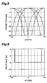
- Fig. 2 is a graph showing the transmission characteristic of the optical filter 200 according to this embodiment.
- the split ratio of each of the first beam splitter 211 and second beam splitter 221 was set to 50%.
- the free spectral range of the second optical system 21 which was determined on the basis of the difference between the optical path lengths d5 and d6 was set to 50 GHz, and the difference between the optical path lengths d2 and d3 of the second and third optical paths P2 and P3 was set to 1.498570 mm.
- the free spectral range determined on the basis of the difference between the optical path lengths d2 and d3 was then set to 100 GHz. Referring to Fig.
- the abscissa represents a deviation ⁇ f from the center frequency at a wavelength of 1550.52 nm (frequency: 193.350 THz).
- the chain line represents the transmission characteristic of a conventional optical filter.
- the optical filter 200 according to this embodiment is superior in isolation to the conventional optical filter.
- the isolation of the optical filter 200 was improved to about 20 dB. Note that there is a difference of 50 GHz between the transmission peak frequency of the transmission characteristic of signal light arriving at the fourth optical path P4 through first optical path P1 and the transmission peak frequency of the transmission characteristic of signal light input through the first optical path P1 and returning to the first optical path P1.
- Fig. 3 is a graph showing the group delay characteristic of the optical filter 200 according to this embodiment.
- the split ratio of each of the first beam splitter 211 and second beam splitter 221 was set to 50%.
- the abscissa represents a deviation ⁇ f from the center frequency at a wavelength of 1550.52 nm (frequency: 193.350 THz).
- no wavelength dispersion i.e., the gradient of the group delay characteristic
- FIG. 4 is view showing the arrangement of an optical filter 201 according to the second embodiment.
- the optical filter 201 has a first optical system 11, second optical system 21, and third optical system 131.
- the first optical system 11 includes a first beam splitter 211.
- the second optical system 21 includes a second beam splitter 221, first reflecting mirror 222, and second reflecting mirror 223.
- the third optical system 131 includes a third beam splitter 231, third reflecting mirror 232, and fourth reflecting mirror 233.
- the first beam splitter 211 splits light arriving through a first optical path P1 into two light beams and outputs one light beam to a second optical path P2 and the other light beam to a third optical path P3.
- the first beam splitter 211 splits the light arriving through the second optical path P2 into two light beams and outputs one light beam to the first optical path P1 and the other light beam to a fourth optical path P4.
- the first beam splitter 211 also splits the light arriving from the third optical path P3 into two light beams and outputs one light beam to the first optical path P1 and the other light beam to the fourth optical path P4.
- the second optical system 21 including the second beam splitter 221, first reflecting mirror 222, and second reflecting mirror 223 forms a Michelson interferometer.
- the second optical system 21 outputs light, output from the first beam splitter 211 to the second optical path P2 and arriving at the second optical system 21, after giving the light an intensity change with wavelength dependence and a phase change. That is, the second beam splitter 221 splits the light arriving through the second optical path P2 into two light beams and outputs one light beam to a fifth optical path P5 and the other light beam to a sixth optical path P6.
- the second beam splitter 221 splits the light arriving through the fifth optical path P5 into two light beams and outputs one light beam to the second optical path P2.
- the second beam splitter 221 also splits the light arriving through the sixth optical path P6 into two light beams and outputs one light beam to the second optical path P2.
- the first reflecting mirror 222 reflects the light arriving through the fifth optical path P5 and outputs the light to the fifth optical path P5.
- the second reflecting mirror 223 reflects the light arriving through the sixth optical path P6 and outputs the light to the sixth optical path P6.
- the third optical system 131 including the third beam splitter 231, third reflecting mirror 232, and fourth reflecting mirror 233 forms a Michelson interferometer.
- the third optical system 131 outputs light, output from the first beam splitter 211 to the third optical path P3 and arriving at the third optical system 131, after giving the light an intensity change with wavelength dependence and a phase change. That is, the third beam splitter 231 splits light arriving through the third optical path P3 into two light beams and outputs one light beam to a seventh optical path P7 and the other light beam to an eighth optical path P8.
- the third beam splitter 231 splits the light arriving through the seventh optical path P7 into two light beams and outputs one light beam to the third optical path P3.
- the third beam splitter 231 also splits the light arriving through the eighth optical path P8 into two light beams and outputs one light beam to the third optical path P3.
- the third reflecting mirror 232 reflects the light arriving through the seventh optical path P7 and outputs the light to the seventh optical path P7.
- the fourth reflecting mirror 233 reflects the light arriving through the eighth optical path P8 and outputs the light to the eighth optical path P8.
- d2 be the length of the second optical path P2 between the first beam splitter 211 and the second beam splitter 221
- d3 be the length of the third optical path P3 between the first beam splitter 211 and the third beam splitter 231
- d5 be the length of the fifth optical path P5 between the second beam splitter 221 and the first reflecting mirror 222
- d6 be the length of the sixth optical path P6 between the second beam splitter 221 and the second reflecting mirror 223
- d7 be the length of the seventh optical path P7 between the third beam splitter 231 and the third reflecting mirror 232
- d8 be the length of the eighth optical path P8 between the third beam splitter 231 and the fourth reflecting mirror 233
- the free spectral range determined on the basis of the difference between the optical path lengths d5 and d6 and the free spectral range determined on the basis of the difference between the optical path lengths d7 and d8 each are set to 1/2 the free spectral range determined on the basis of the difference between
- the first beam splitter 211 has a split ratio of 48% to 52%.
- the second beam splitter 221 and third beam splitter 231 each have a split ratio of 24.9% to 28.9%.
- the optical filter 201 operates as follows. Light incident along the first optical path P1 is split into two light beams by the first beam splitter 211, and one light beam is output to the second optical path P2 while the other light beam is output to the third optical path P3.
- One light beam output to the second optical path P2 is split into two light beams by the second beam splitter 221, and one light beam is output to the fifth optical path P5 while the other light beam is output to the sixth optical path P6.
- the light output to the fifth optical path P5 is reflected by the first reflecting mirror 222 and output to the fifth optical path P5 to arrive at the second beam splitter 221.
- This light is then split into two light beams by the second beam splitter 221, and one light beam is output to the second optical path P2.
- the light output to the sixth optical path P6 is reflected by the second reflecting mirror 223 and output to the sixth optical path P6 to arrive at the second beam splitter 221.
- This light is then split into two light beams by the second beam splitter 221, and one light beam is output to the second optical path P2.
- the light output from the second beam splitter 221 to the second optical path P2 is the light obtained when the light beams arriving at the second beam splitter 221 through the fifth optical path P5 and sixth optical path P6 are partly superimposed on each other.
- the light split by the second beam splitter 221 and output to the second optical path P2 is split into two light beams by the first beam splitter 211, and one light beam is output to the first optical path P1 while the other light beam is output to the fourth optical path P4.
- the other light beam of the light split by the first beam splitter 211 and output to the third optical path P3 is split into two light beams by the third beam splitter 231, and one light beam is output to the seventh optical path P7 while the other light beam is output to the eighth optical path P8.
- the light output to the seventh optical path P7 is reflected by the third reflecting mirror 232 and output to the seventh optical path P7 to arrive at the third beam splitter 231.
- This light is then split into two light beams by the third beam splitter 231, and one light beam is output to the third optical path P3.
- the light output to the eighth optical path P8 is reflected by the fourth reflecting mirror 233 and output to the eighth optical path P8 to arrive at the third beam splitter 231.
- This light is then split into two light beams by the third beam splitter 231, and one light beam is output to the third optical path P3.
- the light output from the third beam splitter 231 to the third optical path P3 is the light obtained when the light beams arriving at the third beam splitter 231 through the seventh optical path P7 and eighth optical path P8 are partly superimposed on each other.
- the light split by the third beam splitter 231 and output to the third optical path P3 is split into two light beams by the first beam splitter 211, and one light beam is output to the first optical path P1 while the other light beam is output to the fourth optical path P4.
- the light output from the first beam splitter 211 to the first optical path P1 is the light obtained when the light beams arriving at the first beam splitter 211 through the second optical path P2 and third optical path P3 are partly superimposed on each other.
- the light output from the first beam splitter 211 to the fourth optical path P4 is also the light obtained when the light beams arriving at the first beam splitter 211 through the second optical path P2 and third optical path P3 are partly superimposed on each other.
- the Michelson interferometer constituted by the first optical system 11 including the first beam splitter 211, the second optical system 21, and the third optical system 131 has a transmission characteristic with a period corresponding to the optical path length difference between the two optical paths.
- the optical filter 201 can therefore receive signal light of multiple wavelengths ( ⁇ 1 , ⁇ 2 ,..., ⁇ 2n-1 , ⁇ 2n ,%) through the first optical path, demultiplex it, and output signal light in a first wavelength range ⁇ 1 ( ⁇ 1 , ⁇ 3 ,..., ⁇ 2n-1 ,...) to the first optical path P1 and signal light in a second wavelength range ⁇ 2 ( ⁇ 2 , ⁇ 4 ,..., ⁇ 2n ,...) to the fourth optical path P4.
- the transmittances of the optical filter 201 in the first wavelength range ⁇ 1 ( ⁇ 1 , ⁇ 3 ,..., ⁇ 2n-1 , ...) and the second wavelength range ⁇ 2 ( ⁇ 2 , ⁇ 4 ,..., ⁇ 2n , ...) exhibit a characteristic more excellent in isolation in accordance with the loss characteristics of the second optical system 21 and third optical system 131 as components of the Michelson interferometer. This characteristic can be realized with a very simple arrangement.
- the free spectral range determined on the basis of the difference between the optical path lengths d5 and d6 and the free spectral range determined on the basis of the difference between the optical path lengths d7 and d8 each are set to 1/2 the free spectral range determined on the basis of the difference between the optical path lengths d2 and d3.
- signal light of multiple wavelengths ( ⁇ 1 , ⁇ 2 ,..., ⁇ 2n-1 , ⁇ 2n ,...) is incident on the optical filter 201 of the second embodiment along the first optical path P1, and the free spectral range determined on the basis of the difference between the optical path lengths d5 and d6 and the free spectral range determined on the basis of the difference between the optical path lengths d7 and d8 each correspond to the wavelength interval of the signal light of multiple wavelengths, one of the signal light in the first wavelength range ⁇ 1 ( ⁇ 1 , ⁇ 3 ,..., ⁇ 2n-1 ,...) and the signal light in the second wavelength range ⁇ 2 ( ⁇ 2 , ⁇ 4 ,..., ⁇ 2n ,...) is output from the first optical path P1, and the other light is output from the fourth optical path P4, thus properly realizing a characteristic excellent in isolation.
- the first beam splitter 211 has a split ratio of 48% to 52%, and the second beam splitter 221 and third beam splitter 231 each have a split ratio of 24.9% to 28.9%. Therefore, the isolation of the optical filter 200 can be improved to about 40 dB.
- the optical filter 201 according to the second embodiment preferably has an isolation of 15 dB or more.
- the optical filter 201 can be applied to a wavelength division multiplexing optical communication system.
- the optical filter 201 according to the second embodiment preferably has a wavelength dispersion of -5 ps/nm or more and 5 ps/nm or less.
- the optical filter 201 can be applied to a wavelength division multiplexing optical communication system, and more specifically, a high-speed wavelength division multiplexing optical communication system with a transmission speed of 40 Gbps.
- Fig. 5 is a graph showing the transmission characteristic of the optical filter 201 according to this embodiment.
- the split ratio of the first beam splitter 211 was set to 50%.
- the split ratio of each of the second beam splitter 221 and third beam splitter 231 was set to 26.9%.
- the free spectral range determined on the basis of the difference between the optical path lengths d5 and d6 and the free spectral range determined on the basis of the difference between the optical path lengths d7 and d8 each were set to 50 GHz, and the difference between the optical path lengths d2 and d3 of the second and third optical paths P2 and P3 was set to 1.498570 mm.
- the free spectral range determined on the basis of the difference between the optical path lengths d2 and d3 was then set to 100 GHz.
- the abscissa represents a deviation ⁇ f from the center frequency at a wavelength of 1550.52 nm (frequency: 193.350 THz).
- the chain line represents the transmission characteristic of a conventional optical filter.
- the optical filter 201 according to this embodiment is superior in isolation to the conventional optical filter.
- the isolation of the optical filter 201 was improved to about 40 dB.
- Fig. 6 is a graph showing the group delay characteristic of the optical filter 201 according to this embodiment.
- the split ratio of the first beam splitter 211 was set to 50%.
- the split ratio of each of the second beam splitter 221 and third beam splitter 231 was set to 26.9%.
- the abscissa represents a deviation ⁇ f from the center frequency at a wavelength of 1550.52 nm (frequency: 193.350 THz).
- no wavelength dispersion i.e., the gradient of the group delay characteristic
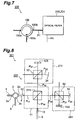
- FIG. 7 is a view showing the arrangement of an interleaver 300 according to this embodiment.
- the interleaver 300 includes an optical circulator 100 and an optical filter 200 (or optical filter 201) according to an embodiment of the present invention.
- the optical circulator 100 has a first terminal 100a, second terminal 100b, and third terminal 100c. Light input to the first terminal 100a is output from the second terminal 100b, and light input to the second terminal 100b is output from the third terminal 100c.
- the optical filter 200 is the optical filter according to the above embodiment.
- a first optical path P1 of the optical filter 200 is connected to the second terminal 100b of the optical circulator 100.
- the interleaver 300 operates as follows. Signal light of multiple wavelengths ( ⁇ 1 , ⁇ 2 ,..., ⁇ 2n-1 , ⁇ 2n ,...) input to the first terminal 100a of the optical circulator 100 is output from the second terminal 100b of the optical circulator 100 and input to the first optical path P1 of the optical filter 200.
- the signal light of the multiple wavelengths input through the first optical path P1 of the optical filter 200 is selected by and transmitted through the optical filter 200, and one of signal light in a first wavelength range ⁇ 1 ( ⁇ 1 , ⁇ 3 ,..., ⁇ 2n-1 ,...) and signal light in a second wavelength range ⁇ 2 ( ⁇ 2 , ⁇ 4 ,..., ⁇ 2n ,...) is output through the first optical path P1 while the other signal light is output through a fourth optical path P4.
- the signal light output through the first optical path P1 of the optical filter 200 is input to the second terminal 100b of the optical circulator 100 and output from the third terminal 100c of the optical circulator 100.
- the signal light of the multiple wavelengths ( ⁇ 1 , ⁇ 2 ,..., ⁇ 2n-1 , ⁇ 2n ,%) is demultiplexed into the signal light in the first wavelength range ⁇ 1 ( ⁇ 1 , ⁇ 3 ,..., ⁇ 2n-1 , ...) and the signal light in the second wavelength range ⁇ 2 ( ⁇ 2 , ⁇ 4 ,..., ⁇ 2n ,...) by the interleaver 300.
- the interleaver 300 since the interleaver 300 has the optical filter 200 (or optical filter 201) excellent in isolation according to the above embodiment, the interleaver exhibits an excellent demultiplexing characteristic.
- FIG. 8 is a view showing the arrangement of the interleaver according to this embodiment.
- An interleaver 301 includes an optical filter 203 including a first optical system 11, second optical system 271, and third optical system 281, and an optical circulator 2.
- the optical circulator 2 has a first terminal 2a, second terminal 2b, and third terminal 2c. Light input to the first terminal 2a through an optical fiber 3 is output from the second terminal 2b to an optical fiber 4, and light input to the second terminal 2b through the optical fiber 4 is output from the third terminal 2c to an optical fiber 5.
- the first optical system 11 has a first port 12, second port 13, and first beam splitter 211.
- the first beam splitter 211 splits light input to the first port 12 and arriving through a first optical path P 11 into two light beams, and outputs one light beam to a second optical path P 12 and the other light beam to a third optical path P 13 .
- the first beam splitter 211 also splits light output and arriving from a second optical system 21 into two light beams, and outputs the light beams to the first optical path P 11 and a fourth optical path P 14 , respectively.
- the first beam splitter 211 splits light output and arriving from a third optical system 31 into two light beams, and outputs the light beams to the first optical path P 11 and fourth optical path P 14 , respectively.
- the second optical system 271 is designed to output the light, output from the first beam splitter 211 to the second optical path P 12 and arriving at the second optical system 271, after giving the light an intensity change having wavelength dependence and a phase change.
- the second optical system 271 has a second beam splitter 22, first etalon filter 123, and second reflecting mirror 24.
- the second optical system 271 including the second beam splitter 22, first etalon filter 123, and second reflecting mirror 24 forms a Michelson interferometer. That is, light arriving at the second beam splitter 22 through the second optical path P 12 is split into two light beams, and the light beams are respectively output to the first etalon filter 123 and the second reflecting mirror 24.
- the light reflected by the first etalon filter 123 and arriving at the second beam splitter 22 is then split into two light beams, and one light beam is output toward the second optical path P 12 (first beam splitter 211).
- the light reflected by the second reflecting mirror 24 and arriving at the second beam splitter 22 is split into two light beams, and one light beam is output to the second optical path P 12 (first beam splitter 211).
- the first etalon filter 123 is a loss filter using multiple reflection between two or more planes, and has a loss characteristic of periodically changing the loss in accordance with a wavelength.
- the first etalon filter 123 is designed to minimize the loss of light arriving from the second beam splitter 22 at each wavelength.
- the first etalon filter 123 gives a loss to light arriving from the second beam splitter 22, and outputs the resultant light to the second beam splitter 22.
- the third optical system 281 gives a phase change and an intensity change with wavelength dependence to light output from the first beam splitter 211 to the third optical path P 13 and arriving at the third optical system 281.
- the third optical system 281 has a third beam splitter 32 different from the first beam splitter 211, a second etalon filter 133, and a fourth reflecting mirror 34.
- the third optical system 281 including the third beam splitter 32, second etalon filter 133, and fourth reflecting mirror 34 forms a Michelson interferometer. That is, light arriving at the third beam splitter 32 through the third optical path P 13 is split into two light beams, and the light beams are output to the second etalon filter 133 and fourth reflecting mirror 34, respectively.
- the light reflected by the fourth reflecting mirror 34 and arriving at the third beam splitter 32 is then split into two light beams, and one light beam is output toward the third optical path P 13 (first beam splitter 211).
- the light reflected by the fourth reflecting mirror 34 and arriving at the third beam splitter 32 is split into two light beams, and one light beam is output to the third optical path P 13 (first beam splitter 211).
- the second etalon filter 133 is a loss filter using multiple reflection between two or more planes, and has a loss characteristic of periodically changing the loss in accordance with a wavelength.
- the second etalon filter 133 is designed to minimize the loss of light arriving from the third beam splitter 32 at each wavelength.
- the second etalon filter 133 gives a loss to light arriving from the third beam splitter 32, and outputs the resultant light to the third beam splitter 32.
- the free spectral range of each of the first etalon filter 123 and second etalon filter 133 is set to 1/2 the free spectral range determined on the basis of the difference between the interval between the first beam splitter 211 and the second beam splitter 22 (the interval (optical path difference) between the splitting point of light at the first beam splitter 211 and the splitting point of light at the second beam splitter 22) and the interval between the first beam splitter 211 and the third beam splitter 32 (the interval (optical path difference) between the splitting point of light at the first beam splitter 211 and the splitting point of light at the third beam splitter 32).
- the light input to the first beam splitter,211 through the first optical path P 11 is split into two light beams by the first beam splitter 211, and one light beam is output to the second optical path P 12 while the other light beam is output to the third optical path P 13 .
- the light output from the first beam splitter 211 to the second optical path P 12 arrives at the second beam splitter 22, the light is split into two light beams by the second beam splitter 22.
- One light beam is then output to an optical path P 21 , and the other light beam is output to an optical path P 22 .
- the light output from the second beam splitter 22 to the optical path P 21 is reflected by the first etalon filter 123 and propagates through the optical path P 21 in reverse to return to the second beam splitter 22.
- the light is then split into two light beams by the second beam splitter 22, and one light beam is then output to the second optical path P 12 .
- the light output from the second beam splitter 22 to the optical path P 22 is reflected by the second reflecting mirror 24 and propagates through the optical path P 22 in reverse to return to the second beam splitter 22.
- the light is then split into two light beams by the second beam splitter 22, and one light beam is then output to the second optical path P 12 .
- the light output from the first beam splitter 211 to the third optical path P 13 arrives at the third beam splitter 32, the light is split into two light beams by the third beam splitter 32.
- One light beam is output to an optical path P 31
- the other light beam is output to an optical path P 32 .
- the light output from the third beam splitter 32 to the optical path P 31 is reflected by the second etalon filter 133 and propagates through the optical path P 31 in reverse to return to the third beam splitter 32.
- the light is then split into two light beams by the third beam splitter 32, and one light beam is then output to the third optical path P 13 .
- the light output from the third beam splitter 32 to the optical path P 32 is reflected by the fourth reflecting mirror 34 and propagates through the optical path P 32 in reverse to return to the third beam splitter 32.
- the light is then split into two light beams by the third beam splitter 32, and one light beam is output to the third optical path P 13 .
- the interleaver 301 including the optical filter 203 operates as follows. Light input to the first terminal 2a of the optical circulator 2 through the optical fiber 3 is output to the second terminal 2b and input from the first port 12 to the first optical system 11 through the optical fiber 4. The light input from the first port 12 of the first optical system 11 is output to the first optical path P 11 . The light input to the first beam splitter 211 through the first optical path P 11 is split into two light beams by the first beam splitter 211. These light beams are output to the second optical path P 12 and third optical path P 13 , respectively.
- the light output to the second optical path P 13 is split into two light beams by the second beam splitter 22 and output to the optical path P 21 .
- the light output to the optical path P 21 propagates to the first etalon filter 123 and returns therefrom to the second beam splitter 22.
- the light input to the second beam splitter 22 is split into two light beams by the second beam splitter 22, and one light beam is output to the second optical path P 12 .
- the light output to the optical path P 22 propagates to the fourth reflecting mirror 34 and returns therefrom to the second beam splitter 22.
- the light input to the second beam splitter 22 is split into two light beams by the second beam splitter 22, and one light beam is output to the second optical path P 12 .
- the light output from the second beam splitter 22 to the second optical path P 12 is the light obtained when the light beams arriving at the second beam splitter 22 through the optical path P 21 and optical path P 22 are partly superimposed on each other.
- the light output to the third optical path P 13 is split into two light beams by the third beam splitter 32 and output to the optical path P 31 .
- the light output to the optical path P 31 propagates to the second etalon filter 133 and returns therefrom to the third beam splitter 32.
- the light input to the third beam splitter 32 is split into two light beams by the third beam splitter 32, and one light beam is output to the third optical path P 13 .
- the light output to the optical path P 32 propagates to the fourth reflecting mirror 34 and returns therefrom to the third beam splitter 32.
- the light input to the third beam splitter 32 is split into two light beams by the third beam splitter 32, one light beam is output to the third optical path P 13 .
- the light output from the third beam splitter 32 to the third optical path P 13 is the light obtained when the light beams arriving at the third beam splitter 32 through the optical path P 31 and optical path P 32 are partly superimposed on each other.
- the light input to the first beam splitter 211 through the second optical path P 12 is split into two light beams by the first beam splitter 211. These light beams are output to the first optical path P 11 and fourth optical path P 14 , respectively.
- the light input to the first beam splitter 211 through the third optical path P 13 is split into two light beams by the first beam splitter 211. These light beams are output to the first optical path P 11 and fourth optical path P 14 , respectively.
- the light output from the first beam splitter 211 to the first optical path P 11 is the light obtained when the light beams arriving at the first beam splitter 211 through the second optical path P 12 and third optical path P 13 are partly superimposed on each other. This light is output from the first port 12 to the optical fiber 4.
- the light output to the optical fiber 4 is input to the first terminal 2a of the optical circulator 2 and output from the third terminal 2c to the optical fiber 5.
- the light output from the first beam splitter 211 to the fourth optical path P 14 is also the light obtained when the light beams arriving at the first beam splitter 211 through the second optical path P 12 and third optical path P 13 are partly superimposed on each other. This light is output to the optical fiber 6 through a second port 13.
- the Michelson interferometer constituted by the first optical system 11 including the first beam splitter 211, the second optical system 271, and the third optical system 281 has a transmission characteristic with a period corresponding to the optical path length difference between the two optical paths.
- the interleaver 301 including the optical filter 203 can therefore receive signal light of multiple wavelengths ( ⁇ 1 , ⁇ 2 ,..., ⁇ 2n-1 , ⁇ 2n ,...) through the optical fiber 3, demultiplex it, and output signal light in a first wavelength range ⁇ 1 ( ⁇ 1 , ⁇ 3 ,..., ⁇ 2n-1 ,...) to the optical fiber 5 and signal light in a second wavelength range ⁇ 2 ( ⁇ 2 , ⁇ 4 ,..., ⁇ 2n ,...) to the optical fiber 6.
- the insertion losses (transmission characteristic) of the interleaver 301 including the optical filter 203 in the first wavelength range ⁇ 1 ( ⁇ 1 , ⁇ 3 ,..., ⁇ 2n-1 ,...) and the second wavelength range ⁇ 2 ( ⁇ 2 , ⁇ 4 ,..., ⁇ 2n ,...) exhibit a characteristic excellent in isolation in accordance with the loss characteristics of the first etalon filter 123 included in the second optical system 121 as a component of the Michelson interferometer and the second etalon filter 133 included in the third optical system 131 as a component of the Michelson interferometer. This characteristic can be realized with a very simple arrangement.
- each of the free spectral ranges of the first etalon filter 123 and second etalon filter 133 is set to 1/2 the free spectral range determined on the basis of the optical path difference between the first beam splitter 211 and the second beam splitter 22 and the optical path difference between the first beam splitter 211 and the third beam splitter 32.
- signal light of multiple wavelengths ( ⁇ 1 , ⁇ 2 ,..., ⁇ 2n-1 , ⁇ 2n ,...) is incident on the optical filter 203 of the fourth embodiment along the first optical path P 11 , and each of the free spectral ranges of the first etalon filter 123 and second etalon filter 133 corresponds to the wavelength intervals of the signal light of the multiple wavelengths, one of the signal light in the first wavelength range ⁇ 1 ( ⁇ 1 , ⁇ 3 ,..., ⁇ 2n-1 ,...) and the signal light in the second wavelength range ⁇ 2 ( ⁇ 2 , ⁇ 4 ,..., ⁇ 2n ,...) is output through the first optical path P 11 while the other is output to the fourth optical path P 14 , thus further properly improving the isolation.
- the isolation of the optical filter 203 can be greatly improved to about 40 dB.
- the optical filter 203 according to the fourth embodiment preferably has an isolation of 15 dB or more.
- the optical filter 203 can be applied to a wavelength division multiplexing optical communication system.
- the optical filter 203 according to the fourth embodiment preferably has a wavelength dispersion of -5 ps/nm or more and 5 ps/nm or less.
- the optical filter 203 can be applied to a wavelength division multiplexing optical communication system, and more specifically, a high-speed wavelength division multiplexing optical communication system with a transmission speed of 40 Gbps.
- FIG. 9 is a view showing the arrangement of the interleaver according to this embodiment.
- An interleaver 302 includes an optical filter 204 including a first port 252, a second port 253, a third port 254, a first optical system 311, second optical system 321, and a third optical system 331, an optical fiber 3, an optical fiber 5, and an optical fiber 6.
- the first optical system 311 has a first beam splitter 312, first etalon filter 313, and first reflecting mirror 314.
- the first optical system 311 including the first beam splitter 312, first etalon filter 313, and first reflecting mirror 314 forms a Michelson interferometer. That is, light arriving at the first beam splitter 312 through a first optical path P 51 is split into two light beams. These light beams are output to the first etalon filter 313 and first reflecting mirror 314, respectively. The light reflected by the first etalon filter 313 and arriving at the first beam splitter 312 is split into two light beams. These light beams are output to a second optical path P 52 and third optical path P 53 , respectively.
- the light reflected by the first reflecting mirror 314 and arriving at the first beam splitter 312 is split into two light beams. These light beams are output to the second optical path P 52 and third optical path P 53 , respectively.
- the first optical system 311 gives light arriving at the first optical system 311 a phase change and an intensity change with wavelength dependence, and outputs the resultant light.
- the first etalon filter 313 is a loss filter using multiple reflection between two or more planes, and has a loss characteristic of periodically changing the loss in accordance with a wavelength.
- the first etalon filter 313 is designed to minimize the loss of light arriving from the first beam splitter 312 at each wavelength.
- the first etalon filter 313 gives a loss to light arriving from the first beam splitter 312, and outputs the resultant light to the first beam splitter 312.
- the free spectral range of the first etalon filter 313 is set to 1/2 the free spectral range determined on the basis of the difference between the interval between the first beam splitter 312 and the first etalon filter 313 (the interval (optical path difference) between the splitting point of light at the first beam splitter 312 and the reflecting point of light at the first etalon filter 313) and the interval between the first beam splitter 312 and the first reflecting mirror 314 (the internal (optical path difference) between the splitting point of light at the first beam splitter 312 and the reflecting point of light at the first reflecting mirror 314).
- the second optical system 321 outputs the light, output from the first beam splitter 312 (first optical system 311) to the second optical path P 52 and arriving at the second optical system 321, after giving the light an intensity change with wavelength dependence and a phase change.
- the second optical system 321 has a second beam splitter 322, second etalon filter 323, and second reflecting mirror 324.
- the second optical system 321 including the second beam splitter 322, second etalon filter 323, and second reflecting mirror 324 forms a Michelson interferometer. That is, light arriving at the second beam splitter 322 through a second optical path P 52 is split into two light beams. These light beams are output to the second etalon filter 323 and second reflecting mirror 324, respectively.
- the light reflected by the second etalon filter 323 and arriving at the second beam splitter 322 is split into two light beams, and one light beam is output to the second port 253.
- the light reflected by the second reflecting mirror 324 and arriving at the second beam splitter 322 is split into two light beams, and one light beam is output to the second port 253.
- the second etalon filter 323 is a loss filter using multiple reflection between two or more planes, and has a loss characteristic of periodically changing the loss in accordance with a wavelength.
- the second etalon filter 323 is designed to minimize the loss of light arriving from the second beam splitter 322 at each wavelength.
- the second etalon filter 323 gives a loss to light arriving from the second beam splitter 322, and outputs the resultant light to the second beam splitter 322.
- the free spectral range of the second etalon filter 323 is set to 1/2 the free spectral range determined on the basis of the difference between the interval between the second beam splitter 322 and the second etalon filter 323 (the interval (optical path difference) between the splitting point of light at the second beam splitter 322 and the reflecting point of light at the second etalon filter 323) and the interval between the second beam splitter 322 and the second reflecting mirror 324 (the internal (optical path difference) between the splitting point of light at the second beam splitter 322 and the reflecting point of light at the second reflecting mirror 324).
- the third optical system 331 outputs the light, output from the first beam splitter 312 (first optical system 311) to the third optical path P 53 and arriving at the third optical system 331, after giving the light an intensity change with wavelength dependence and a phase change.
- the third optical system 331 has a third beam splitter 332, third etalon filter 333, and third reflecting mirror 334.
- the third optical system 331 including the third beam splitter 332, third etalon filter 333, and third reflecting mirror 334 forms a Michelson interferometer. That is, light arriving at the third beam splitter 332 through third optical path P 53 is split into two light beams. These light beams are output to the third etalon filter 333 and third reflecting mirror 334, respectively.
- the light reflected by the third etalon filter 333, and arriving at the third beam splitter 332 is split into two light beams, and one light beam is output to the third port 254.
- the light reflected by the third reflecting mirror 334 and arriving at the third beam splitter 332 is split into two light beams, and one light beam is output to the third port 254.
- the third etalon filter 333 is a loss filter using multiple reflection between two or more planes, and has a loss characteristic of periodically changing the loss in accordance with a wavelength.
- the third etalon filter 333 is designed to minimize the loss of light arriving from the third beam splitter 332 at each wavelength.
- the third etalon filter 333 gives a loss to light arriving from the third beam splitter 332, and outputs the resultant light to the third beam splitter 332.
- the free spectral range of the third etalon filter 333 is set to 1/2 the free spectral range determined on the basis of the difference between the interval between the third beam splitter 332 and the third etalon filter 333 (the interval (optical path difference) between the splitting point of light at the third beam splitter 332 and the reflecting point of light at the third etalon filter 333) and the interval between the third beam splitter 332 and the third reflecting mirror 334 (the internal (optical path difference) between the splitting point of light at the third beam splitter 332 and the reflecting point of light at the third reflecting mirror 334).
- the light input to the first beam splitter 312 through the first optical path P 51 is split into two light beams by the first beam splitter 312, and one light beam is output to a optical path P 61 while the other light beam is output to an optical path P 62 .
- the light output from the first beam splitter 312 to the optical path P 61 is reflected by the first etalon filter 313, propagates through an optical path P 63 , and returns to the first beam splitter 312.
- the light is then split into two light beams by the beam splitter, and one light beam is output to the second optical path P 52 while the other light beam is output to the third optical path P 53 .
- the light output from the first beam splitter 312 to the optical path P 62 is reflected by the first reflecting mirror 314, propagates through an optical path P 64 , and returns to the first beam splitter 312.
- the light is then split into two light beams by the first beam splitter 312, and one light beam is output to the second optical path P 52 while the other light beam is output to the third optical path P 53 .
- the light output from the first optical system 311 (first beam splitter 312) to the second optical path P 52 arrives at the second beam splitter 322, the light is split into two light beams by the second beam splitter 322.
- One light beam is output to an optical path P 65
- the other light beam is output to an optical path P 66 .
- the light output from the second beam splitter 322 to the optical path P 65 is reflected by the second etalon filter 323, propagates through the optical path P 65 in reverse, and returns to the second beam splitter 322.
- the light is then split into two light beams by the second beam splitter 322, and one light beam is output to an optical path P 67 .
- the light output from the second beam splitter 322 to the optical path P 66 is reflected by the second reflecting mirror 324, propagates through the optical path P 66 in reverse, and returns to the second beam splitter 322.
- the light is then split into two light beams by the second beam splitter 322, and one light beam is output to the optical path P 67 .
- One light beam is output to an optical path P 68
- the other light beam is output to an optical path P 69 .
- the light output from the third beam splitter 332 to the optical path P 68 is reflected by the third etalon filter 333, propagates through the optical path P 68 in reverse, and returns to the third beam splitter 332.
- the light is then split into two light beams by the third beam splitter 332, and one light beam is output to an optical path P 70 .
- the light output from the third beam splitter 332 to the optical path P 69 is reflected by the third reflecting mirror 334, propagates through the optical path P 69 in reverse, and returns to the third beam splitter 332.
- the light is then split into two light beams by the third beam splitter 332, and one light beam is output to the optical path P 70 .
- the interleaver 302 including the optical filter 204 operates as follows. Light input to the first port 252 through the optical fiber 3 is output to the first optical path P 51 . The light input to the first beam splitter 312 through the first optical path P 51 is split into two light beams by the first beam splitter 312. These light beams are output to the optical path P 61 and optical path P 62 , respectively. The light output to the optical path P 61 propagates to the first etalon filter 313 and returns therefrom to the first beam splitter 312 through the optical path P 63 . The light input to the first beam splitter 312 through the optical path P 63 is split into two light beams by the first beam splitter 312.
- the light output to the optical path P 62 propagates to the first reflecting mirror 314 and returns therefrom to the first beam splitter 312 through the optical path P 64 .
- the light input to the first beam splitter 312 through the optical path P 64 is split into two light beams by the first beam splitter 312. These light beams are output to the second optical path P 52 and third optical path P 53 , respectively.
- the light output from the first beam splitter 312 to the second optical path P 52 is the light obtained when the light beams arriving at the first beam splitter 312 through the optical path P 63 and optical path P 64 are partly superimposed on each other.
- the light output from the first beam splitter 312 to the third optical path P 53 is the light obtained when the light beams arriving at the first beam splitter 312 through the optical path P 63 and optical path P 64 are partly superimposed on each other.
- the light output to the second optical path P 52 is split into two light beams by the second beam splitter 322. These light beams are output to the optical path P 65 and optical path P 66 , respectively.
- the light output to the optical path P 65 propagates to the second etalon filter 323 and returns therefrom to the second beam splitter 322.
- the light input to the second beam splitter 322 is split into two light beams by the second beam splitter 322, and one light beam is output to the optical path P 67 .
- the light output to the optical path P 66 propagates to the second reflecting mirror 324 and returns therefrom to the second beam splitter 322.
- the light input to the second beam splitter 322 is split into two light beams by the second beam splitter 322, and one light beam is output to the optical path P 67 .
- the light output from the second beam splitter 322 to the optical path P 67 is the light obtained when the light beams arriving at the second beam splitter 322 through the optical path P 65 and optical path P 66 are partly superimposed on each other. This light is output to the optical fiber 5 through the second port 253.
- the light output to the third optical path P 53 is split into two light beams by the third beam splitter 332. These light beams are output to the optical path P 68 and optical path P 69 , respectively.
- the light output to the optical path P 68 propagates to the third etalon filter 333 and returns therefrom to the third beam splitter 332.
- the light input to the third beam splitter 332 is split into two light beams by the third beam splitter 332, and one light beam is output to the optical path P 70 .
- the light output to the optical path P 69 propagates to the third reflecting mirror 334 and returns therefrom to the third beam splitter 332.
- the light input to the third beam splitter 332 is split into two light beams by the third beam splitter 332, and one light beam is output to the optical path P 70 .
- the light output from the third beam splitter 332 to the optical path P 70 is the light obtained when the light beams arriving at the third beam splitter 332 through the optical path P 68 and optical path P 69 are partly superimposed on each other. This light is output to the optical fiber 6 through the third port 254.
- the first optical system 311, second optical system 321, and third optical system 331 constituting the Michelson interferometer each have a transmission characteristic with a period corresponding to the optical path length difference between the two optical paths.
- the interleaver 302 including the optical filter 204 can therefore receive signal light of multiple wavelengths ( ⁇ 1 , ⁇ 2 ,..., ⁇ 2n-1 , ⁇ 2n ,...) through the optical fiber 3, demultiplex it, and output signal light in a first wavelength range ⁇ 1 ( ⁇ 1 , ⁇ 3 ,..., ⁇ 2n-1 ,...) to the optical fiber 5 and signal light in a second wavelength range ⁇ 2 ( ⁇ 2 , ⁇ 4 ,..., ⁇ 2n ,...) to the optical fiber 6.
- the insertion losses (transmission characteristic) of the interleaver 302 including the optical filter 204 in the first wavelength range ⁇ 1 ( ⁇ 1 , ⁇ 3 ,..., ⁇ 2n-1 ,...) and the second wavelength range ⁇ 2 ( ⁇ 2 , ⁇ 4 ,..., ⁇ 2n ,...) exhibit a characteristic excellent in isolation in accordance with the loss characteristics of the first etalon filter 313 included in the first optical system 311 as a component of the Michelson interferometer, the second etalon filter 323 included in the third optical system 321 as a component of the Michelson interferometer, and the third etalon filter 333 included in the third optical system 331 as a component of the Michelson interferometer.
- This characteristic can be realized with a very simple arrangement.
- each of the free spectral ranges of the second etalon filter 323 and third etalon filter 333 is set to 1/2 the free spectral range determined on the basis of the optical path difference between the first beam splitter 312 and the first etalon filter 313 and the optical path difference between the first beam splitter 312 and the first reflecting mirror 314.
- signal light of multiple wavelengths ( ⁇ 1 , ⁇ 2 ,..., ⁇ 2n-1 , ⁇ 2n ,...) is incident on the optical filter 204 of the fifth embodiment along the first optical path P 51 , and each of the free spectral ranges of the second etalon filter 323 and third etalon filter 333 corresponds to the wavelength intervals of the signal light of the multiple wavelengths, one of the signal light in the first wavelength range ⁇ 1 ( ⁇ 1 , ⁇ 3 ,..., ⁇ 2n-1 ,...) and the signal light in the second wavelength range ⁇ 2 ( ⁇ 2 , ⁇ 4 ,..., ⁇ 2n ,...) is output through the optical path P 67 , and the other signal light is output through the optical path P 70 , thus further properly improving the isolation.
- Fig. 10 shows the insertion loss of signal light output from the optical fiber 5 in the interleaver 302 with respect to each frequency. Note that the insertion loss of signal light output from the optical fiber 6 in the interleaver 302 with respect to each frequency differs in wavelength from the characteristic shown in Fig. 10 by 0.4 nm.
- the free spectral range and crosstalk of each of the etalon filters 313, 323, and 333 are set to 50 GHz and 6 dB, respectively.
- a difference of 1.498570 mm is set between the interval between each of the beam splitters 312, 233, and 332 and a corresponding one of the etalon filters 313, 323, and 333 (the interval (optical path difference) between the splitting point of light at each of the beam splitters 312, 322, and 332 and the reflecting point of light at a corresponding one of the etalon filters 313, 323, and 333) and the interval between each of the beam splitters 312, 322, and 332 and a corresponding one of the reflecting mirrors 314, 324, and 334 (the interval (optical path difference) between the splitting point of light at each of the beam splitters 312, 322, and 332 and the reflecting point of light at a corresponding one of the reflecting mirrors 314, 324, and 334).
- the interleaver 302 including the optical filter 204 exhibits characteristics excellent in isolation.
- the broken lines represent the loss characteristic of an interleaver using a conventional Michelson interferometer.
- the optical filter 204 according to the fifth embodiment preferably has an isolation of 15 dB or more.
- the optical filter 204 can be applied to a wavelength division multiplexing optical communication system.
- the optical filter 204 according to the fifth embodiment preferably has a wavelength dispersion of -5 ps/nm or more and 5 ps/nm or less.
- the optical filter 201 can be applied to a wavelength division multiplexing optical communication system, and more specifically, a high-speed wavelength division multiplexing optical communication system with a transmission speed of 40 Gbps.
- FIG. 11 is a view showing the arrangement of the optical communication system 1 according to this embodiment.
- the optical communication system 1 includes optical transmitters 511 and 512, a multiplexing interleaver 513, an optical fiber transmission path 530, a demultiplexing interleaver 523, and optical receivers 521 and 522.
- the demultiplexing interleaver 523 has the same arrangement as that of the interleaver 300 described above. In this case, the interleaver 301 or 302 may be used in place of the interleaver 300.
- One optical transmitter 511 multiplexes signal light beams in a first wavelength range ⁇ 1 ( ⁇ 1 , ⁇ 3 ,..., ⁇ 2n-1 ,...) and outputs the resultant light.
- the other optical transmitter 512 multiplexes signal light beams in a second wavelength range ⁇ 2 ( ⁇ 2 , ⁇ 4 ,..., ⁇ 2n ,...) and outputs the resultant light.
- the multiplexing interleaver 513 receives the signal light of the multiple wavelengths in the first wavelength range ⁇ 1 output from the optical transmitter 511 and the signal light of the multiple wavelengths in the second wavelength range ⁇ 2 output from the optical transmitter 512, multiplexes them, and sends out the resultant light to the optical fiber transmission path 530.
- the demultiplexing interleaver 523 demultiplexes the signal light of the multiple wavelengths in the first wavelength range ⁇ 1 and second wavelength range ⁇ 2 that has arrived through the optical fiber transmission path 530, and outputs the signal light of the multiple wavelengths in the first wavelength range ⁇ 1 to the optical receiver 521 and the signal light of the multiple wavelengths in the second wavelength range ⁇ 2 to the optical receiver 522.
- One optical receiver 521 receives the signal light of the multiple wavelengths in the first wavelength range ⁇ 1 , and demultiplexes it to receive signal light beams of the respective wavelengths.
- the other optical receiver 522 receives the signal light of the multiple wavelengths in the second wavelength range ⁇ 2 , and demultiplexes it to receive signal light beams of the respective wavelengths.
- the demultiplexing interleaver 523 has the same arrangement as that of the above interleaver, and exhibits an excellent demultiplexing characteristic. Since signal light of multiple wavelengths is demultiplexed by the interleaver having an excellent demultiplexing characteristic, the transmission quality of signal light in the optical communication system 1 becomes excellent.
- the present invention is not limited to the above embodiments.
- the interleavers 300 and 301 according to the third and fourth embodiments use optical circulators.
- the necessity of the optical circulators 2 and 100 may be eliminated by adjusting the angles of the respective reflecting mirrors 222, 223, 232, 233, 24, and 34 and the respective etalon filters 123 and 133.
- the second optical system outputs light arriving thereat after giving the light an intensity change with wavelength dependence and a phase change. According to the present invention, this makes it possible to provide an optical filter, interleaver, and optical communication system which are excellent in isolation.
Landscapes
- Physics & Mathematics (AREA)
- General Physics & Mathematics (AREA)
- Optics & Photonics (AREA)
- Electromagnetism (AREA)
- Engineering & Computer Science (AREA)
- Computer Networks & Wireless Communication (AREA)
- Signal Processing (AREA)
- Optical Communication System (AREA)
- Spectrometry And Color Measurement (AREA)
Abstract
A first optical system (11) has a first beam splitter (211). The first beam splitter (211) splits light arriving through a first optical path (P1) into two light beams, and outputs one light beam to a second optical path (P2) and the other light beam to a third optical path (P3). A second optical system (21) outputs the light output from the first beam splitter (221) to the second optical path (P2) and arriving at the second optical system (21) upon giving the light an intensity change with wavelength dependence and a phase change, and has a second beam splitter (221), first reflecting mirror (223), and second reflecting mirror (222). This makes it possible to provide an optical filter (200) which can realize a characteristic excellent in isolation with a very simple arrangement.
Description
- The present invention relates to an optical filter, an interleaver including an optical filter, and an optical communication system having an optical filter or interleaver.
- An interleaver used in an optical communication system is designed to receive signal light of multiple wavelengths (λ1, λ2,..., λ2n-1, λ2n,...) and demultiplex the light into signal light in a first wavelength range Λ1 (λ1, λ3,..., λ2n-1,...) and signal light in a second wavelength range λ2 (λ2, λ4,..., λ2n,...), and is provided for a repeater or the like in the optical communication system. Such interleavers based on various schemes have been proposed. For example, known interleavers include one that includes a polarizing/separating element, wavelength filter, and polarizing/combining element and one that includes an optical system forming a Mach-Zehnder interferometer. An interleaver having an optical filter including an optical system forming a Michelson interferometer is also conceivable.
- In the transmission characteristic of an optical filter including an optical system forming a Michelson interferometer, a transmission peak periodically appears, and each transmission peak characteristic becomes a Gaussian type. The isolation of the optical filter including the optical system forming the Michelson interferometer is inevitably determined. When this optical filter is applied to wavelength division multiplexing optical communication, the isolation between adjacent wavelengths is 9.8 dB, which is lower than that of an optical filter used for general optical communication, i.e., 20 dB. As a consequence, the isolation of the interleaver having the optical filter including the optical system forming the Michelson interferometer also becomes low, and hence the transmission quality of signal light in the wavelength division multiplexing optical communication system having this interleaver is poor.
- The present invention has been made to solve the above problems, and has as its object to provide an optical filter with excellent isolation, an interleaver including the optical filter, and an optical communication system including the optical filter or interleaver.
- An optical filter according to the present invention is characterized by comprising a first optical system which has a first beam splitter, splits light arriving at the first beam splitter through a first optical path into two light beams, and outputs the split light beams to different second and third optical paths, respectively, and a second optical system which outputs light arriving after being output from the first beam splitter to the second optical path upon giving the light an intensity change with wavelength dependence and a phase change.
- In the above optical filter, preferably, the optical filter comprises a reflecting mirror which outputs, to the first beam splitter, light arriving after being output from the first beam splitter to the third optical path, the second optical system outputs light given an intensity change with wavelength dependence and a phase change to the first beam splitter, and the first beam splitter splits light arriving after being output from the second optical system into two light beams, outputs the light beams to the first optical path and a fourth optical path, respectively, also splits light arriving after being output from the reflecting mirror into two light beams, and outputs the light beams to the first and fourth optical paths, respectively.
- Preferably, the second optical system comprises a second beam splitter different from the first beam splitter and first and second reflecting mirrors, splits light arriving through the second optical path into two light beams using the second beam splitter, outputs the light beams to the first and second reflecting mirrors, respectively, splits the light reflected by the first reflecting mirror and arriving at the second beam splitter into two light beams, outputs one light beam to the first beam splitter, splits the light reflected by the second reflecting mirror and arriving at the second beam splitter into two light beams, and outputs one light beam to the first beam splitter.
- Preferably, letting d2 be a length of the second optical path between the first beam splitter and the second beam splitter, d3 be a length of the optical path between the first beam splitter and the reflecting mirror, d5 be a length of the fifth optical path between the second beam splitter and the first reflecting mirror, and d6 be a length of the sixth optical path between the second beam splitter and the second reflecting mirror, a free spectral range determined on the basis of a difference between the optical path lengths d5 and d6 is set to 1/2 a free spectral range determined on the basis of a difference between the optical path lengths d2 and d3.
- The split ratio of each of the first and second beam splitters is preferably 48% to 52%.
- The above optical filter preferably comprises a third optical system which outputs light arriving after being output from the first beam splitter to the third optical path, upon giving the light an intensity change with wavelength dependence and a phase change.
- Preferably, the second optical system outputs light given an intensity change with wavelength dependence and a phase change to the first beam splitter, the third optical system outputs light given an intensity change with wavelength dependence and a phase change to the first beam splitter, and the first beam splitter splits the light arriving after being output from the second optical system into two light beams, outputs the light beams to the first optical path and a fourth optical path, respectively, splits the light arriving after being output from the third optical system into two light beams, and outputs the light beams to the first and fourth optical paths, respectively.
- Preferably, the second optical system comprises a second beam splitter different from the first beam splitter and first and second reflecting mirrors, splits light arriving at the second beam splitter through the second optical path into two light beams, outputs the light beams to the first and second reflecting mirrors, respectively, splits the light reflected by the first reflecting mirror and arriving at the second beam splitter into two light beams, outputs one light beam to the first beam splitter, splits the light reflected by the second reflecting mirror and arriving at the second beam splitter into two light beams, and outputs one light beam to the first beam splitter, and the third optical system comprises a third beam splitter different from the first beam splitter and third and fourth reflecting mirrors, splits light arriving at the third beam splitter through the third optical path into two light beams, outputs the light beams to the third and fourth reflecting mirrors, respectively, splits the light reflected by the third reflecting mirror and arriving at the third beam splitter into two light beams, outputs one light beam to the first beam splitter, splits the light reflected by the fourth reflecting mirror and arriving at the third beam splitter into two light beams, and outputs one light beam to the first beam splitter.
- Preferably, letting d2 be a length of the second optical path between the first beam splitter and the second beam splitter, d3 be a length of the optical path between the first beam splitter and the third beam splitter, d5 be a length of the fifth optical path between the second beam splitter and the first reflecting mirror, d6 be a length of the sixth optical path between the second beam splitter and the second reflecting mirror, d7 be a length of the seventh optical path between the third beam splitter and the third reflecting mirror, and d8 be a length of the eighth optical path between the third beam splitter and the fourth reflecting mirror, a free spectral range determined on the basis of a difference between the optical path lengths d5 and d6 and a free spectral range determined on the basis of a difference between the optical path lengths d7 and d8 each are set to 1/2 a free spectral range determined 'on the basis of a difference between the optical path lengths d2 and d3.
- Preferably, the second optical system comprises a second beam splitter different from the first beam splitter, a first reflecting mirror, and a first etalon filter, splits light arriving at the second beam splitter through the second optical path into two light beams, outputs the light beams to the first reflecting mirror and the first etalon filter, respectively, splits the light reflected by the first reflecting mirror and arriving at the second beam splitter into two light beams, outputs one light beam to the first beam splitter, splits the light reflected by the first etalon filter and arriving at the second beam splitter into two light beams, and outputs one light beam to the first beam splitter, and the third optical system comprises a third beam splitter different from the first beam splitter, a second reflecting mirror, and a second etalon filter, splits light arriving at the third beam splitter through the third optical path into two light beams, outputs the light beams to the second reflecting mirror and the second etalon filter, respectively, splits the light reflected by the second reflecting mirror and arriving at the third beam splitter into two light beams, outputs one light beam to the first beam splitter, splits the light reflected by the second etalon filter and arriving at the third beam splitter into two light beams, and outputs one light beam to the first beam splitter.
- Preferably, letting d2 be a length of the second optical path between the first beam splitter and the second beam splitter, and d3 be a length of the third optical path between the first beam splitter and the third beam splitter, a free spectral range of each of the first and second etalon filters is set to 1/2 a free spectral range determined on the basis of a difference between the optical path lengths d2 and d3.
- Preferably, the split ratio of the first beam splitter is 48% to 52%, and a split ratio of each of the second and third beam splitters is 24.9% to 28.9%.
- Preferably, the first optical system further comprises a first reflecting mirror and a first etalon filter, splits light arriving at the first beam splitter through the first optical path into two light beams, outputs the light beams to the first reflecting mirror and the first etalon filter, respectively, splits light reflected by the first reflecting mirror and arriving at the first beam splitter into two light beams, outputs the light beams to the second and third optical paths, splits light reflected by the first etalon filter and arriving at the first beam splitter into two light beams, and outputs the light beams to the second and third optical paths, respectively, the second optical system comprises a second optical beam splitter different from the first beam splitter, a second reflecting mirror, and a second etalon filter, splits light arriving at the second optical beam splitter through the second optical path into two light beams, outputs the light beams to the second reflecting mirror and the second etalon filter, splits light reflected by the second reflecting mirror and arriving at the second optical beam splitter into two light beams, outputs one light beam to a second port, splits light reflected by the second etalon filter and arriving at the second optical beam splitter into two light beams, and outputs one light beam to the second port, and the third optical system comprises a third optical beam splitter different from the first beam splitter, a third reflecting mirror, and a third etalon filter, splits light arriving at the third optical beam splitter through the third optical path into two light beams, outputs the light beams to the third reflecting mirror and the third etalon filter, respectively, splits light reflected by the third reflecting mirror and arriving at the third optical beam splitter into two light beams, outputs one light beam to a third port, splits light reflected by the third etalon filter and arriving at the third optical beam splitter into two light beams, and outputs one light beam to the third port.
- Preferably, letting d2 be an optical path length between the first beam splitter and the first reflecting mirror, and d3 be an optical path length between the first beam splitter and the first etalon filter, a free spectral range of each of the second and third etalon filters is set to 1/2 a free spectral range determined on the basis of a difference between the optical path length d2 and the optical path length d3.
- The isolation of the above optical filter is preferably not less than 15 dB.
- The wavelength dispersion of the above optical filter is preferably -5 ps/nm to 5 ps/nm.
- An interleaver according to the present invention is characterized by comprising an optical circulator which has a first terminal, a second terminal, and a third terminal, outputs, from the second terminal, light input to the first terminal, and outputs, from the third terminal, light input to the second terminal, and any one of the above optical filters in which the first optical path is connected to the second terminal of the optical circulator.
- An optical communication system according to the present invention is an optical communication system which transmits signal light of multiple wavelengths, characterized by including the above optical filter, the optical filter selecting and transmitting signal light of the signal light of the multiple wavelengths.
- Another optical communication system according to the present invention is an optical communication system which transmits signal light of multiple wavelengths, characterized by including the above interleaver, the interleaver demultiplexing the signal light of the multiple wavelengths.
-
- Fig. 1 is a view showing the arrangement of an
optical filter 200 according to the first embodiment; - Fig. 2 is a graph showing the transmission characteristic of the
optical filter 200 according to the first embodiment; - Fig. 3 is a graph showing the group delay characteristic of the
optical filter 200 according to the first embodiment; - Fig. 4 is a view showing the arrangement of an
optical filter 201 according to the second embodiment; - Fig. 5 is a graph showing the transmission characteristic of the
optical filter 201 according to the second embodiment; - Fig. 6 is a graph showing the group delay characteristic of the
optical filter 201 according to the second embodiment; - Fig. 7 is a view showing the arrangement of an
interleaver 300 according to the third embodiment; - Fig. 8 is a view showing the arrangement of an
interleaver 301 according to the fourth embodiment; - Fig. 9 is a view showing the arrangement of an
interleaver 302 according to the fifth embodiment; - Fig. 10 is a graph showing an insertion loss characteristic of the interleaver according to the fifth embodiment; and
- Fig. 11 is a view showing the arrangement of an
optical communication system 1 according to the sixth embodiment. - Optical filters, interleavers, optical communication systems according to the embodiments of the present invention will be described with reference to the accompanying drawings. In the following description, the same reference numerals denote the same elements or functions, and a repetitive description will be avoided.
- An optical filter according to the first embodiment of the present invention will be described first. Fig. 1 is view showing the arrangement of an
optical filter 200 of the first embodiment. Theoptical filter 200 has a firstoptical system 11, secondoptical system 21, and thirdoptical system 31. - The first
optical system 11 includes afirst beam splitter 211. The secondoptical system 21 includes asecond beam splitter 221, first reflecting mirror (total reflection mirror) 222, and second reflecting mirror (total reflection mirror) 223. The thirdoptical system 31 includes a third reflecting mirror (total reflection mirror) 232. - The
first beam splitter 211 splits light arriving through a first optical path P1 into two light beams and outputs one light beam to a second optical path P2 and the other light beam to a third optical path P3. Thefirst beam splitter 211 splits the light arriving through the second optical path P2 into two light beams and outputs one light beam to the first optical path P1 and the other light beam to a fourth optical path P4. Thefirst beam splitter 211 also splits the light arriving from the third optical path P3 into two light beams and outputs one light beam to the first optical path P1 and the other light beam to the fourth optical path P4. - The second
optical system 21 including thesecond beam splitter 221, first reflectingmirror 222, and second reflectingmirror 223 forms a Michelson interferometer. That is, thesecond beam splitter 221 splits light arriving through the second optical path P2 into two light beams and outputs one light beam to a fifth optical path P5 and the other light beam to a sixth optical path P6. Thesecond beam splitter 221 splits the light arriving through the fifth optical path P5 into two light beams and outputs one light beam to the second optical path P2. Thesecond beam splitter 221 also splits the light arriving through the sixth optical path P6 into two light beams and outputs one light beam to the second optical path P2. The secondoptical system 21 outputs light, output from thefirst beam splitter 211 to the second optical path P2 and arriving at the secondoptical system 21, after giving the light an intensity change with wavelength dependence and a phase change. - The first reflecting
mirror 222 reflects the light arriving through the fifth optical path P5 and outputs the light to the fifth optical path P5. The second reflectingmirror 223 reflects the light arriving through the sixth optical path P6 and outputs the light to the sixth optical path P6. - The third reflecting
mirror 232 of the thirdoptical system 31 reflects the light arriving through the third optical path P3 and outputs the light to the third optical path P3. - Letting d2 be the length of the second optical path P2 between the
first beam splitter 211 and thesecond beam splitter 221, d3 be the length of the third optical path P3 between thefirst beam splitter 211 and the third reflectingmirror 232, d5 be the length of the fifth optical path P5 between thesecond beam splitter 221 and the first reflectingmirror 222, and d6 be the length of the sixth optical path P6 between thesecond beam splitter 221 and the second reflectingmirror 223, the free spectral range (FSR) determined on the basis of the difference between the optical path lengths d5 and d6 is set to 1/2 the free spectral range determined on the basis of the difference between the optical path lengths d2 and d3. - The
optical filter 200 operates as follows. Light incident along the first optical path P1 is split into two light beams by thefirst beam splitter 211, and one light beam is output to the second optical path P2 while the other light beam is output to the third optical path P3. - One light beam output to the second optical path P2 is split into two light beams by the
second beam splitter 221, and one light beam is output to the fifth optical path P5 while the other light beam is output to the sixth optical path P6. The light output to the fifth optical path P5 is reflected by the first reflectingmirror 222, and output to the fifth optical path P5 to arrive at thesecond beam splitter 221. This light is split into two light beams by thesecond beam splitter 221, and one light beam is output to the second optical path P2. The light output to the sixth optical path P6 is reflected by the second reflectingmirror 223 and output to the sixth optical path P6 to arrive at thesecond beam splitter 221. This light is split into two light beams by thesecond beam splitter 221, and one light beam is output to the second optical path P2. The light output from thesecond beam splitter 221 to the second optical path P2 is the light obtained when the light beams arriving at thesecond beam splitter 221 through the fifth optical path P5 and sixth optical path P6 are partly superimposed on each other. - The light split by the
second beam splitter 221 and output to the second optical path P2 is split into two light beams by thefirst beam splitter 211, and one light beam is output to the first optical path P1 while the other light beam is output to the fourth optical path P4. - The other light beam of the light split by the
first beam splitter 211 and output to the third optical path P3 is reflected by the third reflectingmirror 232 and output to the third optical path P3 to arrive at thefirst beam splitter 211. This light is then split into two light beams by thefirst beam splitter 211, and one light beam is output to the first optical path P1 while the other light beam is output to the fourth optical path P4. - The light output from the
first beam splitter 211 to the first optical path P1 is the light obtained when the light beams arriving at thefirst beam splitter 211 through the second optical path P2 and third optical path P3 are partly superimposed on each other. The light output from thefirst beam splitter 211 to the fourth optical path P4 is also the light obtained when the light beams arriving at thefirst beam splitter 211 through the second optical path P2 and third optical path P3 are partly superimposed on each other. - In the
optical filter 200, the Michelson interferometer constituted by the firstoptical system 11 having thefirst beam splitter 211, the secondoptical system 21, and the thirdoptical system 31 having the third reflectingmirror 232 has a transmission characteristic with a period corresponding to the optical path length difference between the two optical paths. Theoptical filter 200 can therefore receive signal light of multiple wavelengths (λ1, λ2,..., λ2n-1, λ2n,...) through the first optical path, demultiplex it, and output signal light in a first wavelength range Λ1 (λ1, λ3,..., λ2n-1,...) to the first optical path and signal light in a second wavelength range Λ2 (λ2, λ4,..., λ2n,...) to the fourth optical path. In this case, λ1 < λ2 < ... < λ2n-1 < λ2n < .... - In addition, the transmittances of the
optical filter 200 in the first wavelength range Λ1 (λ1, λ 3,..., λ2n-1,...) and the second wavelength range Λ2 ( λ2, λ4,..., λ2n,...) exhibit a characteristic excellent in isolation in accordance with the loss characteristic of the secondoptical system 21 as a component of the Michelson interferometer. This characteristic can be realized with a very simple arrangement. - Furthermore, in the
optical filter 200, the free spectral range of the secondoptical system 21 which is determined on the basis of the difference between the optical path lengths d5 and d6 is set to 1/2 the free spectral range determined on the basis of,the difference between the optical path lengths d2 and d3. When, therefore, signal light of multiple wavelengths ( λ1, λ2,..., λ2n-1, λ2n,...) is incident on theoptical filter 200 of the first embodiment along the first optical path P1, and the free spectral range determined on the basis of the difference between the optical path lengths d5 and d6 corresponds to the wavelength interval of the signal light of multiple wavelengths, one of the signal light in the first wavelength range Λ1 (λ1, λ3,..., λ2n-1,...) and the signal light in the second wavelength range Λ2 (λ2, λ 4,..., λ2n,...) is output from the first optical path P1, and the other light is output from the fourth optical path P4, thus a excellent isolation characteristic is properly realized. - The
first beam splitter 211 andsecond beam splitter 221 each preferably have a split ratio of 48% to 52%. In this case, the isolation of theoptical filter 200 can be improved to about 20 dB. - The
optical filter 200 according to the first embodiment preferably has an isolation of 15 dB or more. In this case, theoptical filter 200 can be applied to a wavelength division multiplexing optical communication system. - The
optical filter 200 according to the first embodiment preferably has a wavelength dispersion of -5 ps/nm or more and 5 ps/nm or less. In this case, theoptical filter 200 can be applied to a wavelength division multiplexing optical communication system, and more specifically, a high-speed wavelength division multiplexing optical communication system with a transmission speed of 40 Gbps. - Fig. 2 is a graph showing the transmission characteristic of the
optical filter 200 according to this embodiment. The split ratio of each of thefirst beam splitter 211 andsecond beam splitter 221 was set to 50%. The free spectral range of the secondoptical system 21 which was determined on the basis of the difference between the optical path lengths d5 and d6 was set to 50 GHz, and the difference between the optical path lengths d2 and d3 of the second and third optical paths P2 and P3 was set to 1.498570 mm. The free spectral range determined on the basis of the difference between the optical path lengths d2 and d3 was then set to 100 GHz. Referring to Fig. 2, the abscissa represents a deviation Δf from the center frequency at a wavelength of 1550.52 nm (frequency: 193.350 THz). In this graph, the chain line represents the transmission characteristic of a conventional optical filter. Obviously, theoptical filter 200 according to this embodiment is superior in isolation to the conventional optical filter. The isolation of theoptical filter 200 was improved to about 20 dB. Note that there is a difference of 50 GHz between the transmission peak frequency of the transmission characteristic of signal light arriving at the fourth optical path P4 through first optical path P1 and the transmission peak frequency of the transmission characteristic of signal light input through the first optical path P1 and returning to the first optical path P1. - Fig. 3 is a graph showing the group delay characteristic of the
optical filter 200 according to this embodiment. The split ratio of each of thefirst beam splitter 211 andsecond beam splitter 221 was set to 50%. Referring to Fig. 3, the abscissa represents a deviation Δ f from the center frequency at a wavelength of 1550.52 nm (frequency: 193.350 THz). As shown in Fig. 3, no wavelength dispersion (i.e., the gradient of the group delay characteristic) occurs. - An optical filter according to the second embodiment of the present invention will be described next. Fig. 4 is view showing the arrangement of an
optical filter 201 according to the second embodiment. Theoptical filter 201 has a firstoptical system 11, secondoptical system 21, and thirdoptical system 131. - The first
optical system 11 includes afirst beam splitter 211. The secondoptical system 21 includes asecond beam splitter 221, first reflectingmirror 222, and second reflectingmirror 223. The thirdoptical system 131 includes athird beam splitter 231, third reflectingmirror 232, and fourth reflectingmirror 233. - The
first beam splitter 211 splits light arriving through a first optical path P1 into two light beams and outputs one light beam to a second optical path P2 and the other light beam to a third optical path P3. Thefirst beam splitter 211 splits the light arriving through the second optical path P2 into two light beams and outputs one light beam to the first optical path P1 and the other light beam to a fourth optical path P4. Thefirst beam splitter 211 also splits the light arriving from the third optical path P3 into two light beams and outputs one light beam to the first optical path P1 and the other light beam to the fourth optical path P4. - The second
optical system 21 including thesecond beam splitter 221, first reflectingmirror 222, and second reflectingmirror 223 forms a Michelson interferometer. The secondoptical system 21 outputs light, output from thefirst beam splitter 211 to the second optical path P2 and arriving at the secondoptical system 21, after giving the light an intensity change with wavelength dependence and a phase change. That is, thesecond beam splitter 221 splits the light arriving through the second optical path P2 into two light beams and outputs one light beam to a fifth optical path P5 and the other light beam to a sixth optical path P6. Thesecond beam splitter 221 splits the light arriving through the fifth optical path P5 into two light beams and outputs one light beam to the second optical path P2. Thesecond beam splitter 221 also splits the light arriving through the sixth optical path P6 into two light beams and outputs one light beam to the second optical path P2. - The first reflecting
mirror 222 reflects the light arriving through the fifth optical path P5 and outputs the light to the fifth optical path P5. The second reflectingmirror 223 reflects the light arriving through the sixth optical path P6 and outputs the light to the sixth optical path P6. - The third
optical system 131 including thethird beam splitter 231, third reflectingmirror 232, and fourth reflectingmirror 233 forms a Michelson interferometer. The thirdoptical system 131 outputs light, output from thefirst beam splitter 211 to the third optical path P3 and arriving at the thirdoptical system 131, after giving the light an intensity change with wavelength dependence and a phase change. That is, thethird beam splitter 231 splits light arriving through the third optical path P3 into two light beams and outputs one light beam to a seventh optical path P7 and the other light beam to an eighth optical path P8. Thethird beam splitter 231 splits the light arriving through the seventh optical path P7 into two light beams and outputs one light beam to the third optical path P3. Thethird beam splitter 231 also splits the light arriving through the eighth optical path P8 into two light beams and outputs one light beam to the third optical path P3. - The third reflecting
mirror 232 reflects the light arriving through the seventh optical path P7 and outputs the light to the seventh optical path P7. The fourth reflectingmirror 233 reflects the light arriving through the eighth optical path P8 and outputs the light to the eighth optical path P8. - Letting d2 be the length of the second optical path P2 between the
first beam splitter 211 and thesecond beam splitter 221, d3 be the length of the third optical path P3 between thefirst beam splitter 211 and thethird beam splitter 231, d5 be the length of the fifth optical path P5 between thesecond beam splitter 221 and the first reflectingmirror 222, d6 be the length of the sixth optical path P6 between thesecond beam splitter 221 and the second reflectingmirror 223, d7 be the length of the seventh optical path P7 between thethird beam splitter 231 and the third reflectingmirror 232, and d8 be the length of the eighth optical path P8 between thethird beam splitter 231 and the fourth reflectingmirror 233, the free spectral range determined on the basis of the difference between the optical path lengths d5 and d6 and the free spectral range determined on the basis of the difference between the optical path lengths d7 and d8 each are set to 1/2 the free spectral range determined on the basis of the difference between the optical path lengths d2 and d3. - The
first beam splitter 211 has a split ratio of 48% to 52%. Thesecond beam splitter 221 andthird beam splitter 231 each have a split ratio of 24.9% to 28.9%. - The
optical filter 201 operates as follows. Light incident along the first optical path P1 is split into two light beams by thefirst beam splitter 211, and one light beam is output to the second optical path P2 while the other light beam is output to the third optical path P3. - One light beam output to the second optical path P2 is split into two light beams by the
second beam splitter 221, and one light beam is output to the fifth optical path P5 while the other light beam is output to the sixth optical path P6. The light output to the fifth optical path P5 is reflected by the first reflectingmirror 222 and output to the fifth optical path P5 to arrive at thesecond beam splitter 221. This light is then split into two light beams by thesecond beam splitter 221, and one light beam is output to the second optical path P2. The light output to the sixth optical path P6 is reflected by the second reflectingmirror 223 and output to the sixth optical path P6 to arrive at thesecond beam splitter 221. This light is then split into two light beams by thesecond beam splitter 221, and one light beam is output to the second optical path P2. The light output from thesecond beam splitter 221 to the second optical path P2 is the light obtained when the light beams arriving at thesecond beam splitter 221 through the fifth optical path P5 and sixth optical path P6 are partly superimposed on each other. - The light split by the
second beam splitter 221 and output to the second optical path P2 is split into two light beams by thefirst beam splitter 211, and one light beam is output to the first optical path P1 while the other light beam is output to the fourth optical path P4. - The other light beam of the light split by the
first beam splitter 211 and output to the third optical path P3 is split into two light beams by thethird beam splitter 231, and one light beam is output to the seventh optical path P7 while the other light beam is output to the eighth optical path P8. The light output to the seventh optical path P7 is reflected by the third reflectingmirror 232 and output to the seventh optical path P7 to arrive at thethird beam splitter 231. This light is then split into two light beams by thethird beam splitter 231, and one light beam is output to the third optical path P3. The light output to the eighth optical path P8 is reflected by the fourth reflectingmirror 233 and output to the eighth optical path P8 to arrive at thethird beam splitter 231. This light is then split into two light beams by thethird beam splitter 231, and one light beam is output to the third optical path P3. The light output from thethird beam splitter 231 to the third optical path P3 is the light obtained when the light beams arriving at thethird beam splitter 231 through the seventh optical path P7 and eighth optical path P8 are partly superimposed on each other. - The light split by the
third beam splitter 231 and output to the third optical path P3 is split into two light beams by thefirst beam splitter 211, and one light beam is output to the first optical path P1 while the other light beam is output to the fourth optical path P4. - The light output from the
first beam splitter 211 to the first optical path P1 is the light obtained when the light beams arriving at thefirst beam splitter 211 through the second optical path P2 and third optical path P3 are partly superimposed on each other. The light output from thefirst beam splitter 211 to the fourth optical path P4 is also the light obtained when the light beams arriving at thefirst beam splitter 211 through the second optical path P2 and third optical path P3 are partly superimposed on each other. - In the
optical filter 201, the Michelson interferometer constituted by the firstoptical system 11 including thefirst beam splitter 211, the secondoptical system 21, and the thirdoptical system 131 has a transmission characteristic with a period corresponding to the optical path length difference between the two optical paths. Theoptical filter 201 can therefore receive signal light of multiple wavelengths (λ1, λ2,..., λ2n-1, λ2n,...) through the first optical path, demultiplex it, and output signal light in a first wavelength range Λ1 (λ1, λ3,..., λ2n-1,...) to the first optical path P1 and signal light in a second wavelength range λ2 (λ2, λ4,..., λ 2n,...) to the fourth optical path P4. In this case, λ1 < λ2 < ... < λ2n-1 < λ2n < .... - In addition, the transmittances of the
optical filter 201 in the first wavelength range Λ1 (λ1, λ3,..., λ2n-1, ...) and the second wavelength range Λ2 ( λ2, λ4,..., λ2n, ...) exhibit a characteristic more excellent in isolation in accordance with the loss characteristics of the secondoptical system 21 and thirdoptical system 131 as components of the Michelson interferometer. This characteristic can be realized with a very simple arrangement. - Furthermore, the free spectral range determined on the basis of the difference between the optical path lengths d5 and d6 and the free spectral range determined on the basis of the difference between the optical path lengths d7 and d8 each are set to 1/2 the free spectral range determined on the basis of the difference between the optical path lengths d2 and d3. When, therefore, signal light of multiple wavelengths ( λ1, λ2,..., λ2n-1, λ2n,...) is incident on the
optical filter 201 of the second embodiment along the first optical path P1, and the free spectral range determined on the basis of the difference between the optical path lengths d5 and d6 and the free spectral range determined on the basis of the difference between the optical path lengths d7 and d8 each correspond to the wavelength interval of the signal light of multiple wavelengths, one of the signal light in the first wavelength range Λ1 (λ1, λ3,..., λ2n-1,...) and the signal light in the second wavelength range λ2 (λ2, λ4,..., λ2n,...) is output from the first optical path P1, and the other light is output from the fourth optical path P4, thus properly realizing a characteristic excellent in isolation. - The
first beam splitter 211 has a split ratio of 48% to 52%, and thesecond beam splitter 221 andthird beam splitter 231 each have a split ratio of 24.9% to 28.9%. Therefore, the isolation of theoptical filter 200 can be improved to about 40 dB. - The
optical filter 201 according to the second embodiment preferably has an isolation of 15 dB or more. In this case, theoptical filter 201 can be applied to a wavelength division multiplexing optical communication system. - The
optical filter 201 according to the second embodiment preferably has a wavelength dispersion of -5 ps/nm or more and 5 ps/nm or less. In this case, theoptical filter 201 can be applied to a wavelength division multiplexing optical communication system, and more specifically, a high-speed wavelength division multiplexing optical communication system with a transmission speed of 40 Gbps. - Fig. 5 is a graph showing the transmission characteristic of the
optical filter 201 according to this embodiment. The split ratio of thefirst beam splitter 211 was set to 50%. The split ratio of each of thesecond beam splitter 221 andthird beam splitter 231 was set to 26.9%. The free spectral range determined on the basis of the difference between the optical path lengths d5 and d6 and the free spectral range determined on the basis of the difference between the optical path lengths d7 and d8 each were set to 50 GHz, and the difference between the optical path lengths d2 and d3 of the second and third optical paths P2 and P3 was set to 1.498570 mm. The free spectral range determined on the basis of the difference between the optical path lengths d2 and d3 was then set to 100 GHz. Referring to Fig. 5, the abscissa represents a deviation Δf from the center frequency at a wavelength of 1550.52 nm (frequency: 193.350 THz). In this graph, the chain line represents the transmission characteristic of a conventional optical filter. Obviously, theoptical filter 201 according to this embodiment is superior in isolation to the conventional optical filter. The isolation of theoptical filter 201 was improved to about 40 dB. Note that there is a difference of 50 GHz between the transmission peak frequency of the transmission characteristic of signal light arriving at the fourth optical path P4 through first optical path P1 and the transmission peak frequency of the transmission characteristic of signal light input through the first optical path P1 and returning to the first optical path P1. - Fig. 6 is a graph showing the group delay characteristic of the
optical filter 201 according to this embodiment. The split ratio of thefirst beam splitter 211 was set to 50%. The split ratio of each of thesecond beam splitter 221 andthird beam splitter 231 was set to 26.9%. Referring to Fig. 6, the abscissa represents a deviation Δ f from the center frequency at a wavelength of 1550.52 nm (frequency: 193.350 THz). As shown in Fig. 6, no wavelength dispersion (i.e., the gradient of the group delay characteristic) occurs. - An interleaver according to an embodiment of the present invention will be described next. Fig. 7 is a view showing the arrangement of an
interleaver 300 according to this embodiment. Theinterleaver 300 includes anoptical circulator 100 and an optical filter 200 (or optical filter 201) according to an embodiment of the present invention. - The
optical circulator 100 has afirst terminal 100a,second terminal 100b, and third terminal 100c. Light input to thefirst terminal 100a is output from thesecond terminal 100b, and light input to thesecond terminal 100b is output from thethird terminal 100c. - The
optical filter 200 is the optical filter according to the above embodiment. A first optical path P1 of theoptical filter 200 is connected to the second terminal 100b of theoptical circulator 100. - The
interleaver 300 operates as follows. Signal light of multiple wavelengths (λ1, λ2,..., λ2n-1, λ2n,...) input to the first terminal 100a of theoptical circulator 100 is output from the second terminal 100b of theoptical circulator 100 and input to the first optical path P1 of theoptical filter 200. The signal light of the multiple wavelengths input through the first optical path P1 of theoptical filter 200 is selected by and transmitted through theoptical filter 200, and one of signal light in a first wavelength range Λ1 (λ1, λ3,..., λ2n-1,...) and signal light in a second wavelength range Λ2 (λ2, λ4,..., λ2n,...) is output through the first optical path P1 while the other signal light is output through a fourth optical path P4. The signal light output through the first optical path P1 of theoptical filter 200 is input to the second terminal 100b of theoptical circulator 100 and output from the third terminal 100c of theoptical circulator 100. As a consequence, the signal light of the multiple wavelengths (λ1, λ2,..., λ2n-1, λ2n,...) is demultiplexed into the signal light in the first wavelength range λ1 (λ1, λ3,..., λ2n-1, ...) and the signal light in the second wavelength range Λ2 (λ2, λ 4,..., λ2n,...) by theinterleaver 300. In this case, λ1 < λ2 < ... < λ2n-1 < λ2n < .... - In addition, since the
interleaver 300 has the optical filter 200 (or optical filter 201) excellent in isolation according to the above embodiment, the interleaver exhibits an excellent demultiplexing characteristic. - Another interleaver according to the present invention will be described next. Fig. 8 is a view showing the arrangement of the interleaver according to this embodiment. An
interleaver 301 includes anoptical filter 203 including a firstoptical system 11, secondoptical system 271, and thirdoptical system 281, and anoptical circulator 2. - The
optical circulator 2 has afirst terminal 2a,second terminal 2b, andthird terminal 2c. Light input to thefirst terminal 2a through anoptical fiber 3 is output from thesecond terminal 2b to anoptical fiber 4, and light input to thesecond terminal 2b through theoptical fiber 4 is output from the third terminal 2c to anoptical fiber 5. - The first
optical system 11 has afirst port 12,second port 13, andfirst beam splitter 211. Thefirst beam splitter 211 splits light input to thefirst port 12 and arriving through a first optical path P11 into two light beams, and outputs one light beam to a second optical path P12 and the other light beam to a third optical path P13. Thefirst beam splitter 211 also splits light output and arriving from a secondoptical system 21 into two light beams, and outputs the light beams to the first optical path P11 and a fourth optical path P14, respectively. Thefirst beam splitter 211 splits light output and arriving from a thirdoptical system 31 into two light beams, and outputs the light beams to the first optical path P11 and fourth optical path P14, respectively. - The second
optical system 271 is designed to output the light, output from thefirst beam splitter 211 to the second optical path P12 and arriving at the secondoptical system 271, after giving the light an intensity change having wavelength dependence and a phase change. The secondoptical system 271 has asecond beam splitter 22,first etalon filter 123, and second reflectingmirror 24. The secondoptical system 271 including thesecond beam splitter 22,first etalon filter 123, and second reflectingmirror 24 forms a Michelson interferometer. That is, light arriving at thesecond beam splitter 22 through the second optical path P12 is split into two light beams, and the light beams are respectively output to thefirst etalon filter 123 and the second reflectingmirror 24. The light reflected by thefirst etalon filter 123 and arriving at thesecond beam splitter 22 is then split into two light beams, and one light beam is output toward the second optical path P12 (first beam splitter 211). In addition, the light reflected by the second reflectingmirror 24 and arriving at thesecond beam splitter 22 is split into two light beams, and one light beam is output to the second optical path P12 (first beam splitter 211). - The
first etalon filter 123 is a loss filter using multiple reflection between two or more planes, and has a loss characteristic of periodically changing the loss in accordance with a wavelength. Thefirst etalon filter 123 is designed to minimize the loss of light arriving from thesecond beam splitter 22 at each wavelength. Thefirst etalon filter 123 gives a loss to light arriving from thesecond beam splitter 22, and outputs the resultant light to thesecond beam splitter 22. - The third
optical system 281 gives a phase change and an intensity change with wavelength dependence to light output from thefirst beam splitter 211 to the third optical path P13 and arriving at the thirdoptical system 281. The thirdoptical system 281 has athird beam splitter 32 different from thefirst beam splitter 211, asecond etalon filter 133, and a fourth reflectingmirror 34. The thirdoptical system 281 including thethird beam splitter 32,second etalon filter 133, and fourth reflectingmirror 34 forms a Michelson interferometer. That is, light arriving at thethird beam splitter 32 through the third optical path P13 is split into two light beams, and the light beams are output to thesecond etalon filter 133 and fourth reflectingmirror 34, respectively. The light reflected by the fourth reflectingmirror 34 and arriving at thethird beam splitter 32 is then split into two light beams, and one light beam is output toward the third optical path P13 (first beam splitter 211). In addition, the light reflected by the fourth reflectingmirror 34 and arriving at thethird beam splitter 32 is split into two light beams, and one light beam is output to the third optical path P13 (first beam splitter 211). - The
second etalon filter 133 is a loss filter using multiple reflection between two or more planes, and has a loss characteristic of periodically changing the loss in accordance with a wavelength. Thesecond etalon filter 133 is designed to minimize the loss of light arriving from thethird beam splitter 32 at each wavelength. Thesecond etalon filter 133 gives a loss to light arriving from thethird beam splitter 32, and outputs the resultant light to thethird beam splitter 32. - The free spectral range of each of the
first etalon filter 123 andsecond etalon filter 133 is set to 1/2 the free spectral range determined on the basis of the difference between the interval between thefirst beam splitter 211 and the second beam splitter 22 (the interval (optical path difference) between the splitting point of light at thefirst beam splitter 211 and the splitting point of light at the second beam splitter 22) and the interval between thefirst beam splitter 211 and the third beam splitter 32 (the interval (optical path difference) between the splitting point of light at thefirst beam splitter 211 and the splitting point of light at the third beam splitter 32). - The light input to the first beam splitter,211 through the first optical path P11 is split into two light beams by the
first beam splitter 211, and one light beam is output to the second optical path P12 while the other light beam is output to the third optical path P13. When the light output from thefirst beam splitter 211 to the second optical path P12 arrives at thesecond beam splitter 22, the light is split into two light beams by thesecond beam splitter 22. One light beam is then output to an optical path P21, and the other light beam is output to an optical path P22. - The light output from the
second beam splitter 22 to the optical path P21 is reflected by thefirst etalon filter 123 and propagates through the optical path P21 in reverse to return to thesecond beam splitter 22. The light is then split into two light beams by thesecond beam splitter 22, and one light beam is then output to the second optical path P12. The light output from thesecond beam splitter 22 to the optical path P22 is reflected by the second reflectingmirror 24 and propagates through the optical path P22 in reverse to return to thesecond beam splitter 22. The light is then split into two light beams by thesecond beam splitter 22, and one light beam is then output to the second optical path P12. - When the light output from the
first beam splitter 211 to the third optical path P13 arrives at thethird beam splitter 32, the light is split into two light beams by thethird beam splitter 32. One light beam is output to an optical path P31, and the other light beam is output to an optical path P32. The light output from thethird beam splitter 32 to the optical path P31 is reflected by thesecond etalon filter 133 and propagates through the optical path P31 in reverse to return to thethird beam splitter 32. The light is then split into two light beams by thethird beam splitter 32, and one light beam is then output to the third optical path P13. The light output from thethird beam splitter 32 to the optical path P32 is reflected by the fourth reflectingmirror 34 and propagates through the optical path P32 in reverse to return to thethird beam splitter 32. The light is then split into two light beams by thethird beam splitter 32, and one light beam is output to the third optical path P13. - The
interleaver 301 including theoptical filter 203 operates as follows. Light input to thefirst terminal 2a of theoptical circulator 2 through theoptical fiber 3 is output to thesecond terminal 2b and input from thefirst port 12 to the firstoptical system 11 through theoptical fiber 4. The light input from thefirst port 12 of the firstoptical system 11 is output to the first optical path P11. The light input to thefirst beam splitter 211 through the first optical path P11 is split into two light beams by thefirst beam splitter 211. These light beams are output to the second optical path P12 and third optical path P13, respectively. - The light output to the second optical path P13 is split into two light beams by the
second beam splitter 22 and output to the optical path P21. The light output to the optical path P21 propagates to thefirst etalon filter 123 and returns therefrom to thesecond beam splitter 22. The light input to thesecond beam splitter 22 is split into two light beams by thesecond beam splitter 22, and one light beam is output to the second optical path P12. The light output to the optical path P22 propagates to the fourth reflectingmirror 34 and returns therefrom to thesecond beam splitter 22. The light input to thesecond beam splitter 22 is split into two light beams by thesecond beam splitter 22, and one light beam is output to the second optical path P12. The light output from thesecond beam splitter 22 to the second optical path P12 is the light obtained when the light beams arriving at thesecond beam splitter 22 through the optical path P21 and optical path P22 are partly superimposed on each other. - The light output to the third optical path P13 is split into two light beams by the
third beam splitter 32 and output to the optical path P31. The light output to the optical path P31 propagates to thesecond etalon filter 133 and returns therefrom to thethird beam splitter 32. The light input to thethird beam splitter 32 is split into two light beams by thethird beam splitter 32, and one light beam is output to the third optical path P13. The light output to the optical path P32 propagates to the fourth reflectingmirror 34 and returns therefrom to thethird beam splitter 32. The light input to thethird beam splitter 32 is split into two light beams by thethird beam splitter 32, one light beam is output to the third optical path P13. The light output from thethird beam splitter 32 to the third optical path P13 is the light obtained when the light beams arriving at thethird beam splitter 32 through the optical path P31 and optical path P32 are partly superimposed on each other. - The light input to the
first beam splitter 211 through the second optical path P12 is split into two light beams by thefirst beam splitter 211. These light beams are output to the first optical path P11 and fourth optical path P14, respectively. The light input to thefirst beam splitter 211 through the third optical path P13 is split into two light beams by thefirst beam splitter 211. These light beams are output to the first optical path P11 and fourth optical path P14, respectively. The light output from thefirst beam splitter 211 to the first optical path P11 is the light obtained when the light beams arriving at thefirst beam splitter 211 through the second optical path P12 and third optical path P13 are partly superimposed on each other. This light is output from thefirst port 12 to theoptical fiber 4. The light output to theoptical fiber 4 is input to thefirst terminal 2a of theoptical circulator 2 and output from the third terminal 2c to theoptical fiber 5. The light output from thefirst beam splitter 211 to the fourth optical path P14 is also the light obtained when the light beams arriving at thefirst beam splitter 211 through the second optical path P12 and third optical path P13 are partly superimposed on each other. This light is output to theoptical fiber 6 through asecond port 13. - In the
interleaver 301 including theoptical filter 203, the Michelson interferometer constituted by the firstoptical system 11 including thefirst beam splitter 211, the secondoptical system 271, and the thirdoptical system 281 has a transmission characteristic with a period corresponding to the optical path length difference between the two optical paths. Theinterleaver 301 including theoptical filter 203 can therefore receive signal light of multiple wavelengths (λ1, λ2,..., λ2n-1, λ2n,...) through theoptical fiber 3, demultiplex it, and output signal light in a first wavelength range Λ1 (λ1, λ3,..., λ2n-1,...) to theoptical fiber 5 and signal light in a second wavelength range Λ2 (λ2, λ4,..., λ2n,...) to theoptical fiber 6. In this case, λ1 < λ2 < ... < λ2n-1 < λ2n < .... - In addition, the insertion losses (transmission characteristic) of the
interleaver 301 including theoptical filter 203 in the first wavelength range Λ1 (λ1, λ3,..., λ2n-1,...) and the second wavelength range Λ2 (λ2, λ4,..., λ2n,...) exhibit a characteristic excellent in isolation in accordance with the loss characteristics of thefirst etalon filter 123 included in the second optical system 121 as a component of the Michelson interferometer and thesecond etalon filter 133 included in the thirdoptical system 131 as a component of the Michelson interferometer. This characteristic can be realized with a very simple arrangement. - In addition, each of the free spectral ranges of the
first etalon filter 123 andsecond etalon filter 133 is set to 1/2 the free spectral range determined on the basis of the optical path difference between thefirst beam splitter 211 and thesecond beam splitter 22 and the optical path difference between thefirst beam splitter 211 and thethird beam splitter 32. When, therefore, signal light of multiple wavelengths (λ1, λ2,..., λ2n-1, λ2n,...) is incident on theoptical filter 203 of the fourth embodiment along the first optical path P11, and each of the free spectral ranges of thefirst etalon filter 123 andsecond etalon filter 133 corresponds to the wavelength intervals of the signal light of the multiple wavelengths, one of the signal light in the first wavelength range Λ1 (λ1, λ3,..., λ2n-1,...) and the signal light in the second wavelength range Λ2 (λ 2, λ4,..., λ2n,...) is output through the first optical path P11 while the other is output to the fourth optical path P14, thus further properly improving the isolation. - In this case, if the split ratio of the
first beam splitter 211 is set to 48% to 52%, and each of the split ratios of the second andthird beam splitters optical filter 203 can be greatly improved to about 40 dB. - The
optical filter 203 according to the fourth embodiment preferably has an isolation of 15 dB or more. In this case, theoptical filter 203 can be applied to a wavelength division multiplexing optical communication system. - The
optical filter 203 according to the fourth embodiment preferably has a wavelength dispersion of -5 ps/nm or more and 5 ps/nm or less. In this case, theoptical filter 203 can be applied to a wavelength division multiplexing optical communication system, and more specifically, a high-speed wavelength division multiplexing optical communication system with a transmission speed of 40 Gbps. - Still another interleaver according to the present invention will be described next. Fig. 9 is a view showing the arrangement of the interleaver according to this embodiment. An
interleaver 302 includes anoptical filter 204 including afirst port 252, asecond port 253, athird port 254, a firstoptical system 311, secondoptical system 321, and a thirdoptical system 331, anoptical fiber 3, anoptical fiber 5, and anoptical fiber 6. - The first
optical system 311 has afirst beam splitter 312,first etalon filter 313, and first reflectingmirror 314. The firstoptical system 311 including thefirst beam splitter 312,first etalon filter 313, and first reflectingmirror 314 forms a Michelson interferometer. That is, light arriving at thefirst beam splitter 312 through a first optical path P51 is split into two light beams. These light beams are output to thefirst etalon filter 313 and first reflectingmirror 314, respectively. The light reflected by thefirst etalon filter 313 and arriving at thefirst beam splitter 312 is split into two light beams. These light beams are output to a second optical path P52 and third optical path P53, respectively. In addition, the light reflected by the first reflectingmirror 314 and arriving at thefirst beam splitter 312 is split into two light beams. These light beams are output to the second optical path P52 and third optical path P53, respectively. The firstoptical system 311 gives light arriving at the first optical system 311 a phase change and an intensity change with wavelength dependence, and outputs the resultant light. - The
first etalon filter 313 is a loss filter using multiple reflection between two or more planes, and has a loss characteristic of periodically changing the loss in accordance with a wavelength. Thefirst etalon filter 313 is designed to minimize the loss of light arriving from thefirst beam splitter 312 at each wavelength. Thefirst etalon filter 313 gives a loss to light arriving from thefirst beam splitter 312, and outputs the resultant light to thefirst beam splitter 312. - The free spectral range of the
first etalon filter 313 is set to 1/2 the free spectral range determined on the basis of the difference between the interval between thefirst beam splitter 312 and the first etalon filter 313 (the interval (optical path difference) between the splitting point of light at thefirst beam splitter 312 and the reflecting point of light at the first etalon filter 313) and the interval between thefirst beam splitter 312 and the first reflecting mirror 314 (the internal (optical path difference) between the splitting point of light at thefirst beam splitter 312 and the reflecting point of light at the first reflecting mirror 314). - The second
optical system 321 outputs the light, output from the first beam splitter 312 (first optical system 311) to the second optical path P52 and arriving at the secondoptical system 321, after giving the light an intensity change with wavelength dependence and a phase change. The secondoptical system 321 has asecond beam splitter 322,second etalon filter 323, and second reflectingmirror 324. The secondoptical system 321 including thesecond beam splitter 322,second etalon filter 323, and second reflectingmirror 324 forms a Michelson interferometer. That is, light arriving at thesecond beam splitter 322 through a second optical path P52 is split into two light beams. These light beams are output to thesecond etalon filter 323 and second reflectingmirror 324, respectively. The light reflected by thesecond etalon filter 323 and arriving at thesecond beam splitter 322 is split into two light beams, and one light beam is output to thesecond port 253. In addition, the light reflected by the second reflectingmirror 324 and arriving at thesecond beam splitter 322 is split into two light beams, and one light beam is output to thesecond port 253. - The
second etalon filter 323 is a loss filter using multiple reflection between two or more planes, and has a loss characteristic of periodically changing the loss in accordance with a wavelength. Thesecond etalon filter 323 is designed to minimize the loss of light arriving from thesecond beam splitter 322 at each wavelength. Thesecond etalon filter 323 gives a loss to light arriving from thesecond beam splitter 322, and outputs the resultant light to thesecond beam splitter 322. - The free spectral range of the
second etalon filter 323 is set to 1/2 the free spectral range determined on the basis of the difference between the interval between thesecond beam splitter 322 and the second etalon filter 323 (the interval (optical path difference) between the splitting point of light at thesecond beam splitter 322 and the reflecting point of light at the second etalon filter 323) and the interval between thesecond beam splitter 322 and the second reflecting mirror 324 (the internal (optical path difference) between the splitting point of light at thesecond beam splitter 322 and the reflecting point of light at the second reflecting mirror 324). - The third
optical system 331 outputs the light, output from the first beam splitter 312 (first optical system 311) to the third optical path P53 and arriving at the thirdoptical system 331, after giving the light an intensity change with wavelength dependence and a phase change. The thirdoptical system 331 has athird beam splitter 332,third etalon filter 333, and third reflectingmirror 334. The thirdoptical system 331 including thethird beam splitter 332,third etalon filter 333, and third reflectingmirror 334 forms a Michelson interferometer. That is, light arriving at thethird beam splitter 332 through third optical path P53 is split into two light beams. These light beams are output to thethird etalon filter 333 and third reflectingmirror 334, respectively. The light reflected by thethird etalon filter 333, and arriving at thethird beam splitter 332 is split into two light beams, and one light beam is output to thethird port 254. In addition, the light reflected by the third reflectingmirror 334 and arriving at thethird beam splitter 332 is split into two light beams, and one light beam is output to thethird port 254. - The
third etalon filter 333 is a loss filter using multiple reflection between two or more planes, and has a loss characteristic of periodically changing the loss in accordance with a wavelength. Thethird etalon filter 333 is designed to minimize the loss of light arriving from thethird beam splitter 332 at each wavelength. Thethird etalon filter 333 gives a loss to light arriving from thethird beam splitter 332, and outputs the resultant light to thethird beam splitter 332. - The free spectral range of the
third etalon filter 333 is set to 1/2 the free spectral range determined on the basis of the difference between the interval between thethird beam splitter 332 and the third etalon filter 333 (the interval (optical path difference) between the splitting point of light at thethird beam splitter 332 and the reflecting point of light at the third etalon filter 333) and the interval between thethird beam splitter 332 and the third reflecting mirror 334 (the internal (optical path difference) between the splitting point of light at thethird beam splitter 332 and the reflecting point of light at the third reflecting mirror 334). - The light input to the
first beam splitter 312 through the first optical path P51 is split into two light beams by thefirst beam splitter 312, and one light beam is output to a optical path P61 while the other light beam is output to an optical path P62. The light output from thefirst beam splitter 312 to the optical path P61 is reflected by thefirst etalon filter 313, propagates through an optical path P63, and returns to thefirst beam splitter 312. The light is then split into two light beams by the beam splitter, and one light beam is output to the second optical path P52 while the other light beam is output to the third optical path P53. The light output from thefirst beam splitter 312 to the optical path P62 is reflected by the first reflectingmirror 314, propagates through an optical path P64, and returns to thefirst beam splitter 312. The light is then split into two light beams by thefirst beam splitter 312, and one light beam is output to the second optical path P52 while the other light beam is output to the third optical path P53. - When the light output from the first optical system 311 (first beam splitter 312) to the second optical path P52 arrives at the
second beam splitter 322, the light is split into two light beams by thesecond beam splitter 322. One light beam is output to an optical path P65, and the other light beam is output to an optical path P66. The light output from thesecond beam splitter 322 to the optical path P65 is reflected by thesecond etalon filter 323, propagates through the optical path P65 in reverse, and returns to thesecond beam splitter 322. The light is then split into two light beams by thesecond beam splitter 322, and one light beam is output to an optical path P67. The light output from thesecond beam splitter 322 to the optical path P66 is reflected by the second reflectingmirror 324, propagates through the optical path P66 in reverse, and returns to thesecond beam splitter 322. The light is then split into two light beams by thesecond beam splitter 322, and one light beam is output to the optical path P67. - When the light output from the first optical system 311 (first beam splitter 312) to the third optical path P53 arrives at the
third beam splitter 332, the light is split into two light beams by thethird beam splitter 332. One light beam is output to an optical path P68, and the other light beam is output to an optical path P69. The light output from thethird beam splitter 332 to the optical path P68 is reflected by thethird etalon filter 333, propagates through the optical path P68 in reverse, and returns to thethird beam splitter 332. The light is then split into two light beams by thethird beam splitter 332, and one light beam is output to an optical path P70. The light output from thethird beam splitter 332 to the optical path P69 is reflected by the third reflectingmirror 334, propagates through the optical path P69 in reverse, and returns to thethird beam splitter 332. The light is then split into two light beams by thethird beam splitter 332, and one light beam is output to the optical path P70. - The
interleaver 302 including theoptical filter 204 operates as follows. Light input to thefirst port 252 through theoptical fiber 3 is output to the first optical path P51. The light input to thefirst beam splitter 312 through the first optical path P51 is split into two light beams by thefirst beam splitter 312. These light beams are output to the optical path P61 and optical path P62, respectively. The light output to the optical path P61 propagates to thefirst etalon filter 313 and returns therefrom to thefirst beam splitter 312 through the optical path P63. The light input to thefirst beam splitter 312 through the optical path P63 is split into two light beams by thefirst beam splitter 312. These light beams are output to the second optical path P52 and third optical path P53, respectively. The light output to the optical path P62 propagates to the first reflectingmirror 314 and returns therefrom to thefirst beam splitter 312 through the optical path P64. The light input to thefirst beam splitter 312 through the optical path P64 is split into two light beams by thefirst beam splitter 312. These light beams are output to the second optical path P52 and third optical path P53, respectively. The light output from thefirst beam splitter 312 to the second optical path P52 is the light obtained when the light beams arriving at thefirst beam splitter 312 through the optical path P63 and optical path P64 are partly superimposed on each other. The light output from thefirst beam splitter 312 to the third optical path P53 is the light obtained when the light beams arriving at thefirst beam splitter 312 through the optical path P63 and optical path P64 are partly superimposed on each other. - The light output to the second optical path P52 is split into two light beams by the
second beam splitter 322. These light beams are output to the optical path P65 and optical path P66, respectively. The light output to the optical path P65 propagates to thesecond etalon filter 323 and returns therefrom to thesecond beam splitter 322. The light input to thesecond beam splitter 322 is split into two light beams by thesecond beam splitter 322, and one light beam is output to the optical path P67. The light output to the optical path P66 propagates to the second reflectingmirror 324 and returns therefrom to thesecond beam splitter 322. The light input to thesecond beam splitter 322 is split into two light beams by thesecond beam splitter 322, and one light beam is output to the optical path P67. The light output from thesecond beam splitter 322 to the optical path P67 is the light obtained when the light beams arriving at thesecond beam splitter 322 through the optical path P65 and optical path P66 are partly superimposed on each other. This light is output to theoptical fiber 5 through thesecond port 253. - The light output to the third optical path P53 is split into two light beams by the
third beam splitter 332. These light beams are output to the optical path P68 and optical path P69, respectively. The light output to the optical path P68 propagates to thethird etalon filter 333 and returns therefrom to thethird beam splitter 332. The light input to thethird beam splitter 332 is split into two light beams by thethird beam splitter 332, and one light beam is output to the optical path P70. The light output to the optical path P69 propagates to the third reflectingmirror 334 and returns therefrom to thethird beam splitter 332. The light input to thethird beam splitter 332 is split into two light beams by thethird beam splitter 332, and one light beam is output to the optical path P70. The light output from thethird beam splitter 332 to the optical path P70 is the light obtained when the light beams arriving at thethird beam splitter 332 through the optical path P68 and optical path P69 are partly superimposed on each other. This light is output to theoptical fiber 6 through thethird port 254. - In the
interleaver 302 including theoptical filter 204, the firstoptical system 311, secondoptical system 321, and thirdoptical system 331 constituting the Michelson interferometer each have a transmission characteristic with a period corresponding to the optical path length difference between the two optical paths. Theinterleaver 302 including theoptical filter 204 can therefore receive signal light of multiple wavelengths (λ1, λ2,..., λ2n-1, λ2n,...) through theoptical fiber 3, demultiplex it, and output signal light in a first wavelength range Λ1 (λ1, λ3,..., λ2n-1,...) to theoptical fiber 5 and signal light in a second wavelength range Λ2 (λ2, λ4,..., λ2n,...) to theoptical fiber 6. In this case, λ1 < λ2 < ... < λ2n-1 < λ2n < .... - In addition, the insertion losses (transmission characteristic) of the
interleaver 302 including theoptical filter 204 in the first wavelength range Λ1 ( λ1, λ3,..., λ2n-1,...) and the second wavelength range Λ2 (λ2, λ4,..., λ2n,...) exhibit a characteristic excellent in isolation in accordance with the loss characteristics of thefirst etalon filter 313 included in the firstoptical system 311 as a component of the Michelson interferometer, thesecond etalon filter 323 included in the thirdoptical system 321 as a component of the Michelson interferometer, and thethird etalon filter 333 included in the thirdoptical system 331 as a component of the Michelson interferometer. This characteristic can be realized with a very simple arrangement. - In addition, each of the free spectral ranges of the
second etalon filter 323 andthird etalon filter 333 is set to 1/2 the free spectral range determined on the basis of the optical path difference between thefirst beam splitter 312 and thefirst etalon filter 313 and the optical path difference between thefirst beam splitter 312 and the first reflectingmirror 314. When, therefore, signal light of multiple wavelengths (λ1, λ2,..., λ2n-1, λ2n,...) is incident on theoptical filter 204 of the fifth embodiment along the first optical path P51, and each of the free spectral ranges of thesecond etalon filter 323 andthird etalon filter 333 corresponds to the wavelength intervals of the signal light of the multiple wavelengths, one of the signal light in the first wavelength range Λ1 (λ1, λ3,..., λ2n-1,...) and the signal light in the second wavelength range Λ2 (λ2, λ4,..., λ2n,...) is output through the optical path P67, and the other signal light is output through the optical path P70, thus further properly improving the isolation. - A check result on the insertion loss characteristic of the
interleaver 302 having the above arrangement will be described next with reference to Fig. 10. Fig. 10 shows the insertion loss of signal light output from theoptical fiber 5 in theinterleaver 302 with respect to each frequency. Note that the insertion loss of signal light output from theoptical fiber 6 in theinterleaver 302 with respect to each frequency differs in wavelength from the characteristic shown in Fig. 10 by 0.4 nm. - In this case, the free spectral range and crosstalk of each of the etalon filters 313, 323, and 333 are set to 50 GHz and 6 dB, respectively. A difference of 1.498570 mm is set between the interval between each of the
beam splitters beam splitters beam splitters mirrors beam splitters mirrors - As is obvious from Fig. 10, the
interleaver 302 including theoptical filter 204 exhibits characteristics excellent in isolation. Referring to Fig. 10, the broken lines represent the loss characteristic of an interleaver using a conventional Michelson interferometer. - The
optical filter 204 according to the fifth embodiment preferably has an isolation of 15 dB or more. In this case, theoptical filter 204 can be applied to a wavelength division multiplexing optical communication system. - The
optical filter 204 according to the fifth embodiment preferably has a wavelength dispersion of -5 ps/nm or more and 5 ps/nm or less. In this case, theoptical filter 201 can be applied to a wavelength division multiplexing optical communication system, and more specifically, a high-speed wavelength division multiplexing optical communication system with a transmission speed of 40 Gbps. - An
optical communication system 1 according to this embodiment will be described next. Fig. 11 is a view showing the arrangement of theoptical communication system 1 according to this embodiment. Theoptical communication system 1 includesoptical transmitters multiplexing interleaver 513, an opticalfiber transmission path 530, ademultiplexing interleaver 523, andoptical receivers demultiplexing interleaver 523 has the same arrangement as that of theinterleaver 300 described above. In this case, theinterleaver interleaver 300. - One
optical transmitter 511 multiplexes signal light beams in a first wavelength range Λ1 (λ1, λ3,..., λ2n-1,...) and outputs the resultant light. The otheroptical transmitter 512 multiplexes signal light beams in a second wavelength range Λ2 (λ2, λ4,..., λ2n,...) and outputs the resultant light. Themultiplexing interleaver 513 receives the signal light of the multiple wavelengths in the first wavelength range Λ1 output from theoptical transmitter 511 and the signal light of the multiple wavelengths in the second wavelength range Λ2 output from theoptical transmitter 512, multiplexes them, and sends out the resultant light to the opticalfiber transmission path 530. The demultiplexing interleaver 523 demultiplexes the signal light of the multiple wavelengths in the first wavelength range Λ1 and second wavelength range Λ2 that has arrived through the opticalfiber transmission path 530, and outputs the signal light of the multiple wavelengths in the first wavelength range Λ1 to theoptical receiver 521 and the signal light of the multiple wavelengths in the second wavelength range Λ2 to theoptical receiver 522. Oneoptical receiver 521 receives the signal light of the multiple wavelengths in the first wavelength range Λ1, and demultiplexes it to receive signal light beams of the respective wavelengths. The otheroptical receiver 522 receives the signal light of the multiple wavelengths in the second wavelength range Λ2, and demultiplexes it to receive signal light beams of the respective wavelengths. - In the
optical communication system 1, thedemultiplexing interleaver 523 has the same arrangement as that of the above interleaver, and exhibits an excellent demultiplexing characteristic. Since signal light of multiple wavelengths is demultiplexed by the interleaver having an excellent demultiplexing characteristic, the transmission quality of signal light in theoptical communication system 1 becomes excellent. - The present invention is not limited to the above embodiments. For example, the
interleavers optical circulators mirrors respective etalon filters - As has been described in detail above, according to the present invention, the second optical system outputs light arriving thereat after giving the light an intensity change with wavelength dependence and a phase change. According to the present invention, this makes it possible to provide an optical filter, interleaver, and optical communication system which are excellent in isolation.
Claims (19)
- An optical filter characterized by comprising:a first optical system which has a first beam splitter, splits light arriving at the first beam splitter through a first optical path into two light beams, and outputs the split light beams to different second and third optical paths, respectively; anda second optical system which outputs light arriving after being output from the first beam splitter to the second optical path upon giving the light an intensity change with wavelength dependence and a phase change.
- An optical filter according to claim 1, characterized in that
said optical filter comprises a reflecting mirror which outputs, to the first beam splitter, light arriving after being output from the first beam splitter to the third optical path,
said second optical system outputs light given an intensity change with wavelength dependence and a phase change to the first beam splitter, and
the first beam splitter splits light arriving after being output from said second optical system into two light beams, outputs the light beams to the first optical path and a fourth optical path, respectively, also splits light arriving after being output from said reflecting mirror into two light beams, and outputs the light beams to the first and fourth optical paths, respectively. - An optical filter according to claim 2, characterized in that said second optical system comprises a second beam splitter different from the first beam splitter and first and second reflecting mirrors, splits light arriving through the second optical path into two light beams using the second beam splitter, outputs the light beams to the first and second reflecting mirrors, respectively, splits the light reflected by the first reflecting mirror and arriving at the second beam splitter into two light beams, outputs one light beam to the first beam splitter, splits the light reflected by the second reflecting mirror and arriving at the second beam splitter into two light beams, and outputs one light beam to the first beam splitter.
- An optical filter according to claim 3, characterized in that letting d2 be a length of the second optical path between the first beam splitter and the second beam splitter, d3 be a length of the optical path between the first beam splitter and said reflecting mirror, d5 be a length of the fifth optical path between the second beam splitter and the first reflecting mirror, and d6 be a length of the sixth optical path between the second beam splitter and the second reflecting mirror, a free spectral range determined on the basis of a difference between the optical path lengths d5 and d6 is set to 1/2 a free spectral range determined on the basis of a difference between the optical path lengths d2 and d3.
- An optical filter according to any one of claims 3 and 4, characterized in that a split ratio of each of the first and second beam splitters is 48% to 52%.
- An optical filter according to claim 1, characterized by comprising a third optical system which outputs light arriving after being output from the first beam splitter to the third optical path, upon giving the light an intensity change with wavelength dependence and a phase change.
- An optical filter according to claim 6, characterized in that
said second optical system outputs light given an intensity change with wavelength dependence and a phase change to the first beam splitter,
said third optical system outputs light given an intensity change with wavelength dependence and a phase change to the first beam splitter, and
the first beam splitter splits the light arriving after being output from said second optical system into two light beams, outputs the light beams to the first optical path and a fourth optical path, respectively, splits the light arriving after being output from said third optical system into two light beams, and outputs the light beams to the first and fourth optical paths, respectively. - An optical filter according to claim 7, characterized in that
said second optical system comprises a second beam splitter different from the first beam splitter and first and second reflecting mirrors, splits light arriving at the second beam splitter through the second optical path into two light beams, outputs the light beams to the first and second reflecting mirrors, respectively, splits the light reflected by the first reflecting mirror and arriving at the second beam splitter into two light beams, outputs one light beam to the first beam splitter, splits the light reflected by the second reflecting mirror and arriving at the second beam splitter into two light beams, and outputs one light beam to the first beam splitter, and
said third optical system comprises a third beam splitter different from the first beam splitter and third and fourth reflecting mirrors, splits light arriving at the third beam splitter through the third optical path into two light beams, outputs the light beams to the third and fourth reflecting mirrors, respectively, splits the light reflected by the third reflecting mirror and arriving at the third beam splitter into two light beams, outputs one light beam to the first beam splitter, splits the light reflected by the fourth reflecting mirror and arriving at the third beam splitter into two light beams, and outputs one light beam to the first beam splitter. - An optical filter according to claim 8, characterized in that letting d2 be a length of the second optical path between the first beam splitter and the second beam splitter, d3 be a length of the optical path between the first beam splitter and the third beam splitter, d5 be a length of the fifth optical path between the second beam splitter and the first reflecting mirror, d6 be a length of the sixth optical path between the second beam splitter and the second reflecting mirror, d7 be a length of the seventh optical path between the third beam splitter and the third reflecting mirror, and d8 be a length of the eighth optical path between the third beam splitter and the fourth reflecting mirror, a free spectral range determined on the basis of a difference between the optical path lengths d5 and d6 and a free spectral range determined on the basis of a difference between the optical path lengths d7 and d8 each are set to 1/2 a free spectral range determined on the basis of a difference between the optical path lengths d2 and d3.
- An optical filter according to claim 7, characterized in that
said second optical system comprises a second beam splitter different from the first beam splitter and a first reflecting mirror and a first etalon filter, splits light arriving at the second beam splitter through the second optical path into two light beams, outputs the light beams to the first reflecting mirror and the first etalon filter, respectively, splits the light reflected by the first reflecting mirror and arriving at the second beam splitter into two light beams, outputs one light beam to the first beam splitter, splits the light reflected by the first etalon filter and arriving at the second beam splitter into two light beams, and outputs one light beam to the first beam splitter, and
said third optical system comprises a third beam splitter different from the first beam splitter, a second reflecting mirror, and a second etalon filter, splits light arriving at the third beam splitter through the third optical path into two light beams, outputs the light beams to the second reflecting mirror and the second etalon filter, respectively, splits the light reflected by the second reflecting mirror and arriving at the third beam splitter into two light beams, outputs one light beam to the first beam splitter, splits the light reflected by the second etalon filter and arriving at the third beam splitter into two light beams, and outputs one light beam to the first beam splitter. - An optical filter according to claim 10, characterized in that letting d2 be a length of the second optical path between the first beam splitter and the second beam splitter, and d3 be a length of the third optical path between the first beam splitter and the third beam splitter, a free spectral range of each of the first and second etalon filters is set to 1/2 a free spectral range determined on the basis of a difference between the optical path lengths d2 and d3.
- An optical filter according to any one of claims 8 to 11, characterized in that a split ratio of the first beam splitter is 48% to 52%, and a split ratio of each of the second and third beam splitters is 24.9% to 28.9%.
- An optical filter according to claim 6, characterized in that
said first optical system further comprises a first reflecting mirror and a first etalon filter, splits light arriving at the first beam splitter through the first optical path into two light beams, outputs the light beams to the first reflecting mirror and the first etalon filter, respectively, splits light reflected by the first reflecting mirror and arriving at the first beam splitter into two light beams, outputs the light beams to the second and third optical paths, splits light reflected by the first etalon filter and arriving at the first beam splitter into two light beams, and outputs the light beams to the second and third optical paths, respectively,
said second optical system comprises a second optical beam splitter different from the first beam splitter, a second reflecting mirror, and a second etalon filter, splits light arriving at the second optical beam splitter through the second optical path into two light beams, outputs the light beams to the second reflecting mirror and the second etalon filter, splits light reflected by the second reflecting mirror and arriving at the second optical beam splitter into two light beams, outputs one light beam to a second port, splits light reflected by the second etalon filter and arriving at the second optical beam splitter into two light beams, and outputs one light beam to the second port, and
said third optical system comprises a third optical beam splitter different from the first beam splitter, a third reflecting mirror, and a third etalon filter, splits light arriving at the third optical beam splitter through the third optical path into two light beams, outputs the light beams to the third reflecting mirror and the third etalon filter, respectively, splits light reflected by the third reflecting mirror and arriving at the third optical beam splitter into two light beams, outputs one light beam to a third port, splits light reflected by the third etalon filter and arriving at the third optical beam splitter into two light beams, and outputs one light beam to the third port. - An optical filter according to claim 13, characterized in that letting d2 be an optical path length between the first beam splitter and the first reflecting mirror, and d3 be an optical path length between the first beam splitter and the first etalon filter, a free spectral range of each of the second and third etalon filters is set to 1/2 a free spectral range determined on the basis of a difference between the optical path length d2 and the optical path length d3.
- An optical filter according to any one of claims 1 to 14, characterized in that an isolation is not less than 15 dB.
- An optical filter according to any one of claims 1 to 14, characterized in that a wavelength dispersion is -5 ps/nm to 5 ps/nm.
- An interleaver characterized by comprising:an optical circulator which has a first terminal, a second terminal, and a third terminal, outputs, from the second terminal, light input to the first terminal, and outputs, from the third terminal, light input to the second terminal; andan optical filter defined in any one of claims 1 to 12, in which the first optical path is connected to the second terminal of said optical circulator.
- An optical communication system which transmits signal light of multiple wavelengths, characterized by including an optical filter defined in claims 1 to 16, said optical filter selecting and transmitting signal light of the signal light of the multiple wavelengths.
- An optical communication system which transmits signal light of multiple wavelengths, characterized by including an interleaver defined in claim 17, said interleaver demultiplexing the signal light of the multiple wavelengths.
Applications Claiming Priority (5)
| Application Number | Priority Date | Filing Date | Title |
|---|---|---|---|
| JP2001398019A JP2003198469A (en) | 2001-12-27 | 2001-12-27 | Interleaver |
| JP2001398019 | 2001-12-27 | ||
| JP2002160070 | 2002-05-31 | ||
| JP2002160070A JP2004007232A (en) | 2002-05-31 | 2002-05-31 | Optical filter, interleaver and optical communication system |
| PCT/JP2002/012886 WO2003056725A1 (en) | 2001-12-27 | 2002-12-10 | Optical filter, interleaver, and optical communication system |
Publications (1)
| Publication Number | Publication Date |
|---|---|
| EP1460781A1 true EP1460781A1 (en) | 2004-09-22 |
Family
ID=26625345
Family Applications (1)
| Application Number | Title | Priority Date | Filing Date |
|---|---|---|---|
| EP02783811A Withdrawn EP1460781A1 (en) | 2001-12-27 | 2002-12-10 | Optical filter, interleaver, and optical communication system |
Country Status (6)
| Country | Link |
|---|---|
| US (1) | US6965479B2 (en) |
| EP (1) | EP1460781A1 (en) |
| KR (1) | KR20040073517A (en) |
| CA (1) | CA2471704A1 (en) |
| TW (1) | TW200303433A (en) |
| WO (1) | WO2003056725A1 (en) |
Families Citing this family (5)
| Publication number | Priority date | Publication date | Assignee | Title |
|---|---|---|---|---|
| US20080240736A1 (en) * | 2007-03-28 | 2008-10-02 | Nec Laboratories America, Inc. | Inter-Symbol Interference-Suppressed Colorless DPSK Demodulation |
| US8064768B2 (en) * | 2007-12-19 | 2011-11-22 | Nec Laboratories America, Inc. | Intra-channel equalizing optical interleaver |
| CA2861097A1 (en) | 2012-04-17 | 2013-10-24 | Endure Medical, Inc. | Stereoscopic beam splitter |
| WO2017029752A1 (en) * | 2015-08-20 | 2017-02-23 | 三菱電機株式会社 | Beam scanning device, optical radio communication system, and beam scanning method |
| JP6555110B2 (en) * | 2015-12-08 | 2019-08-07 | 富士通株式会社 | Optical receiver |
Family Cites Families (5)
| Publication number | Priority date | Publication date | Assignee | Title |
|---|---|---|---|---|
| GB8903725D0 (en) * | 1989-02-18 | 1989-04-05 | Cambridge Consultants | Coherent tracking sensor |
| JP3235077B2 (en) * | 1991-09-28 | 2001-12-04 | 株式会社ニコン | Exposure apparatus, exposure method using the apparatus, and method for manufacturing semiconductor device using the apparatus |
| KR100258183B1 (en) * | 1997-09-08 | 2000-06-01 | 정선종 | Inter-channel delay compensation multiwavelength channel transmission optical filter |
| JP3555532B2 (en) * | 2000-01-13 | 2004-08-18 | 日立電線株式会社 | Michelson interferometer type optical multiplexer / demultiplexer |
| JP2001333015A (en) * | 2000-05-22 | 2001-11-30 | Fujitsu Ltd | Optical multiplexing device and optical multiplexing method |
-
2002
- 2002-12-10 CA CA002471704A patent/CA2471704A1/en not_active Abandoned
- 2002-12-10 US US10/468,895 patent/US6965479B2/en not_active Expired - Fee Related
- 2002-12-10 WO PCT/JP2002/012886 patent/WO2003056725A1/en not_active Ceased
- 2002-12-10 KR KR10-2004-7010119A patent/KR20040073517A/en not_active Withdrawn
- 2002-12-10 EP EP02783811A patent/EP1460781A1/en not_active Withdrawn
- 2002-12-20 TW TW091136800A patent/TW200303433A/en unknown
Non-Patent Citations (1)
| Title |
|---|
| See references of WO03056725A1 * |
Also Published As
| Publication number | Publication date |
|---|---|
| KR20040073517A (en) | 2004-08-19 |
| CA2471704A1 (en) | 2003-07-10 |
| US6965479B2 (en) | 2005-11-15 |
| US20040075902A1 (en) | 2004-04-22 |
| TW200303433A (en) | 2003-09-01 |
| WO2003056725A1 (en) | 2003-07-10 |
Similar Documents
| Publication | Publication Date | Title |
|---|---|---|
| US6222958B1 (en) | Optical interleaver/de-interleaver | |
| US6125220A (en) | Interferometric optical device including a resonant optical cavity | |
| US6281977B1 (en) | Interferometric optical device including an optical resonator | |
| US8121485B2 (en) | RF-photonic transversal filter method and apparatus | |
| Hsieh et al. | Flat-top interleavers using two Gires-Tournois etalons as phase-dispersive mirrors in a Michelson interferometer | |
| US6765679B2 (en) | Multi-cavity interferometer with dispersion compensating resonators | |
| US6907167B2 (en) | Optical interleaving with enhanced spectral response and reduced polarization sensitivity | |
| US6721506B1 (en) | Method and system for delivering multi-band broadcast services in wavelength division multiplexed passive optical networks | |
| US5953470A (en) | Circuit for optical WDM system | |
| US6252716B1 (en) | Bulk optic interleaver | |
| EP1061674A2 (en) | Wavelength division multiplexed optical communication system having tunable multi-channel dispersion compensating filters | |
| US20090162066A1 (en) | Intra-Channel Equalizing Optical Interleaver | |
| US6965479B2 (en) | Optical filter, interleaver, and optical communication system | |
| EP1016884A2 (en) | Interferometric optical device including an optical resonator | |
| US6546160B1 (en) | Transceiver for wavelength multiplexing processes | |
| US6678441B1 (en) | Multireflector fiber optic filter apparatus and method | |
| US6785000B2 (en) | Bulk optical interferometer | |
| Hsieh et al. | Flat-top and low-dispersion interleavers using Gires–Tournois etalons as phase dispersive mirrors in a Michelson interferometer | |
| US8005328B2 (en) | Optical add/drop module | |
| US6768843B1 (en) | Cascaded fourier filter interleaver having enhanced performance | |
| US20030035619A1 (en) | Cascaded optical filters | |
| US6768591B2 (en) | Interleaver | |
| US6640026B2 (en) | Optical multiplexer and demultiplexer | |
| Dingel | Recent developments of novel optical interleavers: performance and potential | |
| JP2004007232A (en) | Optical filter, interleaver and optical communication system |
Legal Events
| Date | Code | Title | Description |
|---|---|---|---|
| PUAI | Public reference made under article 153(3) epc to a published international application that has entered the european phase |
Free format text: ORIGINAL CODE: 0009012 |
|
| 17P | Request for examination filed |
Effective date: 20040615 |
|
| AK | Designated contracting states |
Kind code of ref document: A1 Designated state(s): AT BE BG CH CY CZ DE DK EE ES FI FR GB GR IE IT LI LU MC NL PT SE SI SK TR |
|
| AX | Request for extension of the european patent |
Extension state: AL LT LV MK RO |
|
| STAA | Information on the status of an ep patent application or granted ep patent |
Free format text: STATUS: THE APPLICATION HAS BEEN WITHDRAWN |
|
| 18W | Application withdrawn |
Effective date: 20070117 |