EP1460292A1 - Laminated bushing - Google Patents
Laminated bushing Download PDFInfo
- Publication number
- EP1460292A1 EP1460292A1 EP03251613A EP03251613A EP1460292A1 EP 1460292 A1 EP1460292 A1 EP 1460292A1 EP 03251613 A EP03251613 A EP 03251613A EP 03251613 A EP03251613 A EP 03251613A EP 1460292 A1 EP1460292 A1 EP 1460292A1
- Authority
- EP
- European Patent Office
- Prior art keywords
- grooves
- bushing
- resilient material
- metal sheet
- disposed
- Prior art date
- Legal status (The legal status is an assumption and is not a legal conclusion. Google has not performed a legal analysis and makes no representation as to the accuracy of the status listed.)
- Granted
Links
- 239000002184 metal Substances 0.000 claims abstract description 47
- 239000012858 resilient material Substances 0.000 claims abstract description 46
- 238000004804 winding Methods 0.000 claims abstract description 4
- 230000033001 locomotion Effects 0.000 claims description 46
- 238000000034 method Methods 0.000 claims description 14
- 239000000725 suspension Substances 0.000 claims description 9
- 239000003381 stabilizer Substances 0.000 claims description 7
- 239000004636 vulcanized rubber Substances 0.000 claims 1
- 239000000463 material Substances 0.000 abstract description 10
- 230000004044 response Effects 0.000 description 3
- 230000008901 benefit Effects 0.000 description 2
- 230000006835 compression Effects 0.000 description 2
- 238000007906 compression Methods 0.000 description 2
- 230000001419 dependent effect Effects 0.000 description 2
- 230000004048 modification Effects 0.000 description 2
- 238000012986 modification Methods 0.000 description 2
- 235000004443 Ricinus communis Nutrition 0.000 description 1
- 239000000853 adhesive Substances 0.000 description 1
- 230000001070 adhesive effect Effects 0.000 description 1
- 230000005540 biological transmission Effects 0.000 description 1
- 230000015572 biosynthetic process Effects 0.000 description 1
- 239000011248 coating agent Substances 0.000 description 1
- 238000000576 coating method Methods 0.000 description 1
- 230000026058 directional locomotion Effects 0.000 description 1
- 230000007246 mechanism Effects 0.000 description 1
- 238000005096 rolling process Methods 0.000 description 1
- 238000004073 vulcanization Methods 0.000 description 1
Images


Classifications
-
- F—MECHANICAL ENGINEERING; LIGHTING; HEATING; WEAPONS; BLASTING
- F16—ENGINEERING ELEMENTS AND UNITS; GENERAL MEASURES FOR PRODUCING AND MAINTAINING EFFECTIVE FUNCTIONING OF MACHINES OR INSTALLATIONS; THERMAL INSULATION IN GENERAL
- F16F—SPRINGS; SHOCK-ABSORBERS; MEANS FOR DAMPING VIBRATION
- F16F3/00—Spring units consisting of several springs, e.g. for obtaining a desired spring characteristic
- F16F3/08—Spring units consisting of several springs, e.g. for obtaining a desired spring characteristic with springs made of a material having high internal friction, e.g. rubber
- F16F3/10—Spring units consisting of several springs, e.g. for obtaining a desired spring characteristic with springs made of a material having high internal friction, e.g. rubber combined with springs made of steel or other material having low internal friction
- F16F3/12—Spring units consisting of several springs, e.g. for obtaining a desired spring characteristic with springs made of a material having high internal friction, e.g. rubber combined with springs made of steel or other material having low internal friction the steel spring being in contact with the rubber spring
-
- B—PERFORMING OPERATIONS; TRANSPORTING
- B60—VEHICLES IN GENERAL
- B60G—VEHICLE SUSPENSION ARRANGEMENTS
- B60G11/00—Resilient suspensions characterised by arrangement, location or kind of springs
- B60G11/02—Resilient suspensions characterised by arrangement, location or kind of springs having leaf springs only
- B60G11/10—Resilient suspensions characterised by arrangement, location or kind of springs having leaf springs only characterised by means specially adapted for attaching the spring to axle or sprung part of the vehicle
- B60G11/12—Links, pins, or bushes
-
- B—PERFORMING OPERATIONS; TRANSPORTING
- B60—VEHICLES IN GENERAL
- B60G—VEHICLE SUSPENSION ARRANGEMENTS
- B60G11/00—Resilient suspensions characterised by arrangement, location or kind of springs
- B60G11/14—Resilient suspensions characterised by arrangement, location or kind of springs having helical, spiral or coil springs only
- B60G11/15—Coil springs resisting deflection by winding up
-
- B—PERFORMING OPERATIONS; TRANSPORTING
- B60—VEHICLES IN GENERAL
- B60G—VEHICLE SUSPENSION ARRANGEMENTS
- B60G11/00—Resilient suspensions characterised by arrangement, location or kind of springs
- B60G11/18—Resilient suspensions characterised by arrangement, location or kind of springs having torsion-bar springs only
- B60G11/20—Resilient suspensions characterised by arrangement, location or kind of springs having torsion-bar springs only characterised by means specially adapted for attaching the spring to axle or sprung part of the vehicle
-
- B—PERFORMING OPERATIONS; TRANSPORTING
- B60—VEHICLES IN GENERAL
- B60G—VEHICLE SUSPENSION ARRANGEMENTS
- B60G11/00—Resilient suspensions characterised by arrangement, location or kind of springs
- B60G11/22—Resilient suspensions characterised by arrangement, location or kind of springs having rubber springs only
- B60G11/23—Resilient suspensions characterised by arrangement, location or kind of springs having rubber springs only of the torsional-energy-absorption type
-
- B—PERFORMING OPERATIONS; TRANSPORTING
- B60—VEHICLES IN GENERAL
- B60G—VEHICLE SUSPENSION ARRANGEMENTS
- B60G21/00—Interconnection systems for two or more resiliently-suspended wheels, e.g. for stabilising a vehicle body with respect to acceleration, deceleration or centrifugal forces
- B60G21/02—Interconnection systems for two or more resiliently-suspended wheels, e.g. for stabilising a vehicle body with respect to acceleration, deceleration or centrifugal forces permanently interconnected
- B60G21/04—Interconnection systems for two or more resiliently-suspended wheels, e.g. for stabilising a vehicle body with respect to acceleration, deceleration or centrifugal forces permanently interconnected mechanically
- B60G21/05—Interconnection systems for two or more resiliently-suspended wheels, e.g. for stabilising a vehicle body with respect to acceleration, deceleration or centrifugal forces permanently interconnected mechanically between wheels on the same axle but on different sides of the vehicle, i.e. the left and right wheel suspensions being interconnected
- B60G21/055—Stabiliser bars
- B60G21/0551—Mounting means therefor
-
- B—PERFORMING OPERATIONS; TRANSPORTING
- B60—VEHICLES IN GENERAL
- B60G—VEHICLE SUSPENSION ARRANGEMENTS
- B60G7/00—Pivoted suspension arms; Accessories thereof
- B60G7/02—Attaching arms to sprung part of vehicle
-
- F—MECHANICAL ENGINEERING; LIGHTING; HEATING; WEAPONS; BLASTING
- F16—ENGINEERING ELEMENTS AND UNITS; GENERAL MEASURES FOR PRODUCING AND MAINTAINING EFFECTIVE FUNCTIONING OF MACHINES OR INSTALLATIONS; THERMAL INSULATION IN GENERAL
- F16F—SPRINGS; SHOCK-ABSORBERS; MEANS FOR DAMPING VIBRATION
- F16F1/00—Springs
- F16F1/02—Springs made of steel or other material having low internal friction; Wound, torsion, leaf, cup, ring or the like springs, the material of the spring not being relevant
- F16F1/025—Springs made of steel or other material having low internal friction; Wound, torsion, leaf, cup, ring or the like springs, the material of the spring not being relevant characterised by having a particular shape
- F16F1/027—Planar, e.g. in sheet form; leaf springs
-
- F—MECHANICAL ENGINEERING; LIGHTING; HEATING; WEAPONS; BLASTING
- F16—ENGINEERING ELEMENTS AND UNITS; GENERAL MEASURES FOR PRODUCING AND MAINTAINING EFFECTIVE FUNCTIONING OF MACHINES OR INSTALLATIONS; THERMAL INSULATION IN GENERAL
- F16F—SPRINGS; SHOCK-ABSORBERS; MEANS FOR DAMPING VIBRATION
- F16F1/00—Springs
- F16F1/02—Springs made of steel or other material having low internal friction; Wound, torsion, leaf, cup, ring or the like springs, the material of the spring not being relevant
- F16F1/04—Wound springs
- F16F1/10—Spiral springs with turns lying substantially in plane surfaces
-
- F—MECHANICAL ENGINEERING; LIGHTING; HEATING; WEAPONS; BLASTING
- F16—ENGINEERING ELEMENTS AND UNITS; GENERAL MEASURES FOR PRODUCING AND MAINTAINING EFFECTIVE FUNCTIONING OF MACHINES OR INSTALLATIONS; THERMAL INSULATION IN GENERAL
- F16F—SPRINGS; SHOCK-ABSORBERS; MEANS FOR DAMPING VIBRATION
- F16F1/00—Springs
- F16F1/02—Springs made of steel or other material having low internal friction; Wound, torsion, leaf, cup, ring or the like springs, the material of the spring not being relevant
- F16F1/18—Leaf springs
- F16F1/20—Leaf springs with layers, e.g. anti-friction layers, or with rollers between the leaves
-
- F—MECHANICAL ENGINEERING; LIGHTING; HEATING; WEAPONS; BLASTING
- F16—ENGINEERING ELEMENTS AND UNITS; GENERAL MEASURES FOR PRODUCING AND MAINTAINING EFFECTIVE FUNCTIONING OF MACHINES OR INSTALLATIONS; THERMAL INSULATION IN GENERAL
- F16F—SPRINGS; SHOCK-ABSORBERS; MEANS FOR DAMPING VIBRATION
- F16F1/00—Springs
- F16F1/36—Springs made of rubber or other material having high internal friction, e.g. thermoplastic elastomers
- F16F1/38—Springs made of rubber or other material having high internal friction, e.g. thermoplastic elastomers with a sleeve of elastic material between a rigid outer sleeve and a rigid inner sleeve or pin, i.e. bushing-type
-
- B—PERFORMING OPERATIONS; TRANSPORTING
- B60—VEHICLES IN GENERAL
- B60G—VEHICLE SUSPENSION ARRANGEMENTS
- B60G2202/00—Indexing codes relating to the type of spring, damper or actuator
- B60G2202/10—Type of spring
- B60G2202/14—Plastic spring, e.g. rubber
- B60G2202/142—Plastic spring, e.g. rubber subjected to shear, e.g. Neidhart type
- B60G2202/1424—Torsional
-
- B—PERFORMING OPERATIONS; TRANSPORTING
- B60—VEHICLES IN GENERAL
- B60G—VEHICLE SUSPENSION ARRANGEMENTS
- B60G2204/00—Indexing codes related to suspensions per se or to auxiliary parts
- B60G2204/10—Mounting of suspension elements
- B60G2204/12—Mounting of springs or dampers
- B60G2204/121—Mounting of leaf springs
-
- B—PERFORMING OPERATIONS; TRANSPORTING
- B60—VEHICLES IN GENERAL
- B60G—VEHICLE SUSPENSION ARRANGEMENTS
- B60G2204/00—Indexing codes related to suspensions per se or to auxiliary parts
- B60G2204/10—Mounting of suspension elements
- B60G2204/12—Mounting of springs or dampers
- B60G2204/122—Mounting of torsion springs
- B60G2204/1222—Middle mounts of stabiliser on vehicle body or chassis
-
- B—PERFORMING OPERATIONS; TRANSPORTING
- B60—VEHICLES IN GENERAL
- B60G—VEHICLE SUSPENSION ARRANGEMENTS
- B60G2204/00—Indexing codes related to suspensions per se or to auxiliary parts
- B60G2204/10—Mounting of suspension elements
- B60G2204/14—Mounting of suspension arms
- B60G2204/143—Mounting of suspension arms on the vehicle body or chassis
-
- B—PERFORMING OPERATIONS; TRANSPORTING
- B60—VEHICLES IN GENERAL
- B60G—VEHICLE SUSPENSION ARRANGEMENTS
- B60G2204/00—Indexing codes related to suspensions per se or to auxiliary parts
- B60G2204/40—Auxiliary suspension parts; Adjustment of suspensions
- B60G2204/41—Elastic mounts, e.g. bushings
Definitions
- This invention relates to a resilient joint bushing for use in joining two structural members.
- bushing is used to connect two structural members that move relative to one anther.
- bushings include an inner sleeve of a predetermined diameter secured to one of the structural members and an outer sleeve having a diameter larger then the inner sleeve.
- the inner sleeve is suspended within the outer sleeve in a concentric manner by a resilient and deformable material.
- the deformable material is typically bonded to both the inner and outer sleeves.
- the deformable material disposed between the inner and outer sleeves allows a discrete amount of movement.
- the movement between inner and outer sleeves may be longitudinal or rotational.
- Such bushings dampen the transmission of vibrations from one structural member to another reducing noise created by such vibrations. This type of bushing does not direct motion between the structural parts.
- One other type of bushing is a laminated bushing. Sheets of metal and deformable material are layered to form this type of bushing.
- the laminated bushing can have greater strength and durability properties than the above-mentioned bushing.
- laminated bushings may be constructed in a manner that can aid in the direction of movement between structural members. This is accomplished by layering the alternating metal sheets to provide for shear in only desired directions. Laminated bushings however are costly in comparison to typical bushings.
- One disclosed embodiment of this invention is a laminated bushing formed by spirally winding a metal sheet with a resilient material to provide a range of motion proportional to an applied force.
- the laminated bushing includes a metal sheet spirally wound about a first longitudinal axis forming a spirally shaped cavity.
- a deformable resilient material such as rubber is disposed on one side of the metal sheet and within the cavity.
- the metal sheet forming the spiral shaped cavity may mechanically compress the resilient material disposed within the cavities.
- the resilient material can be vulcanized once within the laminated bushing is formed.
- the spirally wound laminated bushing includes inner and outer sleeves concentric about the longitudinal axis and that move relative to one another in direct proportion to the material deformation properties of the resilient material disposed between the metal sheet.
- the resilient material is alternatively layered with the metal sheet the direction of movement between the inner sleeve and the outer sleeve is controlled by the specific configuration of the laminated bushing.
- the configuration of the laminated bushing can be adapted to provide various directions of movement between two fastened structural members.
- the inner sleeve is concentric with the outer sleeve.
- the outer sleeve forms a continuous cylinder and movement of the inner sleeve relative to the outer sleeves can occur in many planes.
- the laminated bushing includes a plurality of grooves disposed annularly about the longitudinal axis. Movement of the resilient material is resisted at a greater rate in a direction across or perpendicular to the grooves. In this way the grooves can be configured to direct motion between the two structural members by increasing resistance to movement across the grooves. Further embodiments include grooves that are disposed along the longitudinal axis, and grooves that are spirally wound about longitudinal axis.
- the invention includes the method of constructing a spirally wound bushing including the steps of bonding a resilient deformable material to a least one side of a metal sheet, then rolling the metal sheet over itself about a longitudinal axis such that a plurality of spirally wound cavities are formed.
- the method further includes forming the spirally wound cavities such that the resilient deformable material is compressed within the spiral cavities.
- the laminated bushing of the subject invention provide the benefits of increased strength and durability along with providing a means of directionally controlling movement of a structural member.
- the laminated bushing 10 includes a metal sheet 12 spirally wound about a longitudinal axis 14 to form a spirally shaped cavity 20.
- a resilient material 16 such as rubber is disposed between the metal sheet 12 and within the spiral shaped cavity 20.
- the resilient material 16 is mechanically compressed between the metal sheets 12.
- the resilient material 16 can be rubber that is vulcanized after formation of the bushing 10. It should be understood that the resilient material 16 could be of any type known in the art.
- the inner sleeve 22 is rotatable relative to an outer sleeve 18 in a proportional manner related to the specific material properties of the resilient material 16.
- the spirally wound metal sheet 12 is inserted into the outer sleeve 18.
- the inner sleeve 22 is formed concentric with the outer sleeve 18 about the longitudinal axis 14.
- the inner sleeve 22 is movable along the longitudinal axis 14 relative to the outer sleeve 18 in a proportional manner dependent on the specific properties of the resilient material 16.
- another embodiment of the laminated bushing includes a plurality of mechanically formed grooves 24.
- the grooves 24 are formed at intervals along the axis 14 of the laminated bushing 10.
- the grooves 24 are part of the metal sheet and become an integral part of the laminated bushing throughout the entire spirally wound bushing 10.
- the grooves 24 direct movement of the inner sleeve 22 relative to the outer sleeve 18 by increasing the resistance to movement in a direction across or perpendicular to the grooves 24.
- the grooves 24 increase resistance of the resilient material 16 in a direction perpendicular to the grooves 24.
- the grooves 24 are arranged at intervals about the longitudinal axis 14 to increase resistance to movement of the inner sleeve 22 along the longitudinal axis 14 relative to the outer sleeve 18.
- FIG. 3 another embodiment including a plurality of grooves 26 is disclosed.
- the grooves 26 are positioned longitudinally throughout the entire laminated bushing 10.
- the grooves are formed within the metal sheet 12 to direct movement of the inner sleeve 22 relative to the outer sleeve 18 by increasing resistance to motion perpendicular to the grooves 26.
- the longitudinal grooves 26 resist rotational movement of the inner sleeve 22 relative to the outer sleeve 18 thereby encouraging movement along the longitudinal axis 14. Movement along the longitudinal axis 14 would be such that the inner sleeve 22 moves in a telescoping motion relative to the outer sleeve 18.
- the laminated bushing includes a plurality of spirally wound grooves 28 within the metal sheet 12 such that the resilient material 16 is directed for both rotational and axial movement.
- the spirally wound groves 28 direct the inner sleeve 22 to rotate about the longitudinal axis 14 in proportion to movement along the longitudinal axis 14.
- the spirally wound grooves 28 direct movement of the inner sleeve 22 relative to the outer sleeve 18 along the longitudinal axis 14 in proportion to rotation about the longitudinal axis 14.
- the inner sleeve 22 has a lower resistance to movement in a telescoping, rotational manner relative to the outer sleeve 18.
- the laminated bushings 10 enable control of the direction of motion by using alternating layers of metal sheet 12 and resilient material 16 with or without the formed geometry.
- the embodiments of the laminated bushing described and shown in Figures 1-4 are only examples of various geometric configurations integrally formed to the laminated bushing 10 to control motion of the inner sleeve 22 relative to the outer sleeve 18. It should be understood that it is within the contemplation of this invention that the grooves may be of any configuration known to a worker skilled in the art such that the direction of motion can be controlled dependent on a specific application.
- the laminated bushing 10 can be incorporated into any application in which bushings are currently being used such as for joining of various suspension components.
- a leaf spring assembly 44 including the laminated bushings 10 having spirally wound grooves 28.
- the laminated bushings 10 enable control of the direction of motion to assist in the changing wheel alignment by changing chamber, castor, toe and the like.
- the laminated bushings 10 are part of the hanger bracket 46 and move proportionally in response to compression of the leaf spring assembly 44. Movement of the leaf spring assembly 44 can be used to direct movement of the leaf spring assembly 44 to adjust over-steer or under-steer.
- the laminated bushings 10 are arranged such that compression of the leaf spring 44 moves the rear bushing in one direction and moves the front bushing in the opposite direction to provide a pivoting movement of the entire leaf spring assembly 44 as shown by the arrows A.
- the laminated bushings 10 secure mounting brackets 46 for a stabilizer bar 48 to direct and control movement of the stabilizer bar 48 proportionally to an applied force.
- the stabilizer bar 48 is mounted within the laminated bushings 10 that are in turn mounted to the body of the motor vehicle schematically shown as 47.
- the ends of the stabilizer bar 50 are attached to a wheel assembly (Not Shown) of the motor vehicle such that during a turn one arm of the stabilizer bar is twisted to transmit a counter rotational force across the vehicle to a side opposite the turn to inhibit roll of the body of the motor vehicle 47.
- the laminated bushings 10 controls the amount of rotation in proportional response to the applied forces such that a roll rate of the vehicle body 47 is controlled.
- the laminated bushings 10 can include spirally wound grooves 28 to control linear movement along an axis 51 as well as rotational movement.
- a wheel assembly 52 including upper and lower control arms 54, 56 pivotally attached to a frame member 62 at one end and to a spindle arm 60 opposite the frame member 62.
- Each pivotal connection 64 includes a laminated bushing 10.
- the laminated bushings are configured to direct and control relative movement between the upper, lower, and spindle arms 54,56, and 60 in response to forces applied to each pivotal connection 64 by movement of the wheel assembly 52.
- FIG. 8 another embodiment of the laminated bushing 10 is shown as a door hinge 64 to allow directional motion of the door as well as providing a means of holding a door 66 open in various intermediate positions.
- the laminated bushing 10 is mounted vertically along an axis 14 and includes spirally wound grooves 28.
- the laminated bushing 10 is mounted to a support 68 such that the weight of a door 66 is exerted downward onto the laminated bushing 10.
- the spirally wound grooves 28 are disposed on the laminated bushing 10 such that opening of the door 66 moves the inner sleeve 22 upwardly an amount proportional to the amount in which the door 66 is opened or rotated.
- the weight of the door 66 exerts a force downward on the laminated bushing 10 such that the door 66 will be directed to rotate toward a closed position.
- the downward force exerted on the laminated bushing 10 causes the door 66 to rotate toward the closed position.
- the invention also includes a method of forming the laminated bushing 10 including the steps of affixing a resilient material to the metal sheet.
- the resilient material 16 may be affixed by any means known in the art such as utilizing adhesive or coating a metal sheet 12 with the resilient material 16.
- the resilient material 16 and metal sheet 12 are in turn spirally wound back about the longitudinal axis 14 to form a spirally shaped cavity 20 with the metal sheet 12 such that the resilient material 16 is disposed within the spirally shaped cavity 20.
- the spirally wound metal sheet and resilient material 16 is in turn inserted between an inner sleeve 22 and an outer sleeve 18.
- the metal sheet 12 may be secured back onto itself to form the inner and outer sleeves 22,18 from a common metal sheet 12.
- the inner sleeve 22 is preferably concentric with the outer sleeve 18.
- the resilient material 16 is mechanically compressed within the spirally shaped cavity 20 during the winding step to form alternating layers of metal sheet 12 and resilient material 16.
- the resilient material 16 is composed of rubber and adhered to the metal sheet 12 by a vulcanization process as is known in the art.
- the vulcanized resilient material 16 adheres to the metal sheet 12 of the laminated bushing 10.
- the method also includes the step of mechanically forming a plurality of grooves within the metal sheet.
- the grooves 24 may be of any configuration and extend in any direction.
- the resilient material is then adhered to the metal sheet 12 and wound to form the spiral cavity 20.
- the method also includes the step of forming a length 72 of laminated bushings 10.
- the laminated bushing 10 may be formed from a metal sheet having a length 70 longer than that required for a specific application, then cut into smaller required lengths 72.
Landscapes
- Engineering & Computer Science (AREA)
- Mechanical Engineering (AREA)
- General Engineering & Computer Science (AREA)
- Springs (AREA)
- Support Of The Bearing (AREA)
Abstract
Description
- This invention relates to a resilient joint bushing for use in joining two structural members.
- Typically, a bushing is used to connect two structural members that move relative to one anther. Normally, bushings include an inner sleeve of a predetermined diameter secured to one of the structural members and an outer sleeve having a diameter larger then the inner sleeve. In one type of bushing, the inner sleeve is suspended within the outer sleeve in a concentric manner by a resilient and deformable material. The deformable material is typically bonded to both the inner and outer sleeves. The deformable material disposed between the inner and outer sleeves allows a discrete amount of movement. The movement between inner and outer sleeves may be longitudinal or rotational. Such bushings dampen the transmission of vibrations from one structural member to another reducing noise created by such vibrations. This type of bushing does not direct motion between the structural parts.
- One other type of bushing is a laminated bushing. Sheets of metal and deformable material are layered to form this type of bushing. The laminated bushing can have greater strength and durability properties than the above-mentioned bushing. Further, laminated bushings may be constructed in a manner that can aid in the direction of movement between structural members. This is accomplished by layering the alternating metal sheets to provide for shear in only desired directions. Laminated bushings however are costly in comparison to typical bushings.
- For these reasons, it is desirable to develop a low cost laminated bushing to provide additional strength and durability while providing a cost efficient alternative to conventional bushings.
- One disclosed embodiment of this invention is a laminated bushing formed by spirally winding a metal sheet with a resilient material to provide a range of motion proportional to an applied force.
- The laminated bushing includes a metal sheet spirally wound about a first longitudinal axis forming a spirally shaped cavity. A deformable resilient material such as rubber is disposed on one side of the metal sheet and within the cavity. The metal sheet forming the spiral shaped cavity may mechanically compress the resilient material disposed within the cavities. Alternatively, the resilient material can be vulcanized once within the laminated bushing is formed. The spirally wound laminated bushing includes inner and outer sleeves concentric about the longitudinal axis and that move relative to one another in direct proportion to the material deformation properties of the resilient material disposed between the metal sheet. However, because the resilient material is alternatively layered with the metal sheet the direction of movement between the inner sleeve and the outer sleeve is controlled by the specific configuration of the laminated bushing.
- The configuration of the laminated bushing can be adapted to provide various directions of movement between two fastened structural members. In one embodiment, the inner sleeve is concentric with the outer sleeve. The outer sleeve forms a continuous cylinder and movement of the inner sleeve relative to the outer sleeves can occur in many planes.
- In another embodiment, the laminated bushing includes a plurality of grooves disposed annularly about the longitudinal axis. Movement of the resilient material is resisted at a greater rate in a direction across or perpendicular to the grooves. In this way the grooves can be configured to direct motion between the two structural members by increasing resistance to movement across the grooves. Further embodiments include grooves that are disposed along the longitudinal axis, and grooves that are spirally wound about longitudinal axis.
- The invention includes the method of constructing a spirally wound bushing including the steps of bonding a resilient deformable material to a least one side of a metal sheet, then rolling the metal sheet over itself about a longitudinal axis such that a plurality of spirally wound cavities are formed. The method further includes forming the spirally wound cavities such that the resilient deformable material is compressed within the spiral cavities.
- The laminated bushing of the subject invention provide the benefits of increased strength and durability along with providing a means of directionally controlling movement of a structural member.
- The various features and advantages of this invention will become apparent to those skilled in the art from the following detailed description of the currently preferred embodiment. The drawings that accompany the detailed description can be briefly described as follows:
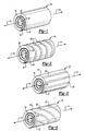
- Figure 1 is a perspective view of a spirally wound laminated bushing;
- Figure 2 is a perspective view of another embodiment of the laminated bushing including annular grooves;
- Figure 3 is a perspective view of another embodiment of the laminated bushing with longitudinal grooves;
- Figure 4, is another embodiment of the laminated bushing including spiral grooves;
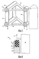
- Figure 5 is a perspective view of the spirally wound laminated bushing installed in a leaf spring bracket assembly;
- Figure 6, is a perspective view of another application of the laminated bushing to support a stabilizer bar;
- Figure 7, is a perspective view of another application of the laminated bushing installed in upper and lower control arms of a wheel assembly;
- Figure 8 is a plan view of a laminated bushing used as a hinge mechanism for a door.
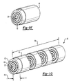
- Figure 9A-9D are schematic views of the method steps for fabricating the spirally wound laminated bushing; and
- Figure 10 is a perspective view the method step of cutting a laminated bushing to a required length.
- Referring to the Figures, wherein like numerals indicate like or corresponding parts throughout the several views and embodiments, a laminated bushing generally indicated at 10 is shown in Figure 1. The laminated
bushing 10 includes ametal sheet 12 spirally wound about alongitudinal axis 14 to form a spirallyshaped cavity 20. Aresilient material 16 such as rubber is disposed between themetal sheet 12 and within the spiral shapedcavity 20. Preferably, theresilient material 16 is mechanically compressed between themetal sheets 12. Alternatively, theresilient material 16 can be rubber that is vulcanized after formation of thebushing 10. It should be understood that theresilient material 16 could be of any type known in the art. Preferably, theinner sleeve 22 is rotatable relative to anouter sleeve 18 in a proportional manner related to the specific material properties of theresilient material 16. The spirally woundmetal sheet 12 is inserted into theouter sleeve 18. Theinner sleeve 22 is formed concentric with theouter sleeve 18 about thelongitudinal axis 14. Theinner sleeve 22 is movable along thelongitudinal axis 14 relative to theouter sleeve 18 in a proportional manner dependent on the specific properties of theresilient material 16. - Referring to Figure 2, another embodiment of the laminated bushing includes a plurality of mechanically formed
grooves 24. Thegrooves 24 are formed at intervals along theaxis 14 of the laminatedbushing 10. Preferably, thegrooves 24 are part of the metal sheet and become an integral part of the laminated bushing throughout the entire spirally wound bushing 10. Thegrooves 24 direct movement of theinner sleeve 22 relative to theouter sleeve 18 by increasing the resistance to movement in a direction across or perpendicular to thegrooves 24. Thegrooves 24 increase resistance of theresilient material 16 in a direction perpendicular to thegrooves 24. In this embodiment, thegrooves 24 are arranged at intervals about thelongitudinal axis 14 to increase resistance to movement of theinner sleeve 22 along thelongitudinal axis 14 relative to theouter sleeve 18. - Referring to Figure 3, another embodiment including a plurality of
grooves 26 is disclosed. In this embodiment, thegrooves 26 are positioned longitudinally throughout the entirelaminated bushing 10. The grooves are formed within themetal sheet 12 to direct movement of theinner sleeve 22 relative to theouter sleeve 18 by increasing resistance to motion perpendicular to thegrooves 26. Thelongitudinal grooves 26 resist rotational movement of theinner sleeve 22 relative to theouter sleeve 18 thereby encouraging movement along thelongitudinal axis 14. Movement along thelongitudinal axis 14 would be such that theinner sleeve 22 moves in a telescoping motion relative to theouter sleeve 18. - Referring to Figure 4, another embodiment of the
laminated bushing 10 is shown. The laminated bushing includes a plurality ofspirally wound grooves 28 within themetal sheet 12 such that theresilient material 16 is directed for both rotational and axial movement. Thespirally wound groves 28 direct theinner sleeve 22 to rotate about thelongitudinal axis 14 in proportion to movement along thelongitudinal axis 14. Thespirally wound grooves 28 direct movement of theinner sleeve 22 relative to theouter sleeve 18 along thelongitudinal axis 14 in proportion to rotation about thelongitudinal axis 14. In other words, theinner sleeve 22 has a lower resistance to movement in a telescoping, rotational manner relative to theouter sleeve 18. - The
laminated bushings 10 enable control of the direction of motion by using alternating layers ofmetal sheet 12 andresilient material 16 with or without the formed geometry. The embodiments of the laminated bushing described and shown in Figures 1-4 are only examples of various geometric configurations integrally formed to thelaminated bushing 10 to control motion of theinner sleeve 22 relative to theouter sleeve 18. It should be understood that it is within the contemplation of this invention that the grooves may be of any configuration known to a worker skilled in the art such that the direction of motion can be controlled dependent on a specific application. Thelaminated bushing 10 can be incorporated into any application in which bushings are currently being used such as for joining of various suspension components. - Referring to Figure 5, a
leaf spring assembly 44 is shown including thelaminated bushings 10 having spirally woundgrooves 28. Thelaminated bushings 10 enable control of the direction of motion to assist in the changing wheel alignment by changing chamber, castor, toe and the like. Thelaminated bushings 10 are part of thehanger bracket 46 and move proportionally in response to compression of theleaf spring assembly 44. Movement of theleaf spring assembly 44 can be used to direct movement of theleaf spring assembly 44 to adjust over-steer or under-steer. Thelaminated bushings 10 are arranged such that compression of theleaf spring 44 moves the rear bushing in one direction and moves the front bushing in the opposite direction to provide a pivoting movement of the entireleaf spring assembly 44 as shown by the arrows A. - Referring to Figure 6, in this embodiment the
laminated bushings 10 secure mountingbrackets 46 for astabilizer bar 48 to direct and control movement of thestabilizer bar 48 proportionally to an applied force. Thestabilizer bar 48 is mounted within thelaminated bushings 10 that are in turn mounted to the body of the motor vehicle schematically shown as 47. The ends of thestabilizer bar 50 are attached to a wheel assembly (Not Shown) of the motor vehicle such that during a turn one arm of the stabilizer bar is twisted to transmit a counter rotational force across the vehicle to a side opposite the turn to inhibit roll of the body of themotor vehicle 47. Thelaminated bushings 10 controls the amount of rotation in proportional response to the applied forces such that a roll rate of thevehicle body 47 is controlled. In this embodiment thelaminated bushings 10 can include spirally woundgrooves 28 to control linear movement along anaxis 51 as well as rotational movement. - Referring to Figure 7, a
wheel assembly 52 including upper andlower control arms frame member 62 at one end and to aspindle arm 60 opposite theframe member 62. Eachpivotal connection 64 includes alaminated bushing 10. The laminated bushings are configured to direct and control relative movement between the upper, lower, andspindle arms pivotal connection 64 by movement of thewheel assembly 52. - Referring to Figure 8, another embodiment of the
laminated bushing 10 is shown as adoor hinge 64 to allow directional motion of the door as well as providing a means of holding adoor 66 open in various intermediate positions. Thelaminated bushing 10 is mounted vertically along anaxis 14 and includes spirally woundgrooves 28. Thelaminated bushing 10 is mounted to asupport 68 such that the weight of adoor 66 is exerted downward onto thelaminated bushing 10. Thespirally wound grooves 28 are disposed on thelaminated bushing 10 such that opening of thedoor 66 moves theinner sleeve 22 upwardly an amount proportional to the amount in which thedoor 66 is opened or rotated. The weight of thedoor 66 exerts a force downward on thelaminated bushing 10 such that thedoor 66 will be directed to rotate toward a closed position. The downward force exerted on thelaminated bushing 10 causes thedoor 66 to rotate toward the closed position. - Referring to Figures 9A-9D, the invention also includes a method of forming the
laminated bushing 10 including the steps of affixing a resilient material to the metal sheet. Theresilient material 16 may be affixed by any means known in the art such as utilizing adhesive or coating ametal sheet 12 with theresilient material 16. Theresilient material 16 andmetal sheet 12 are in turn spirally wound back about thelongitudinal axis 14 to form a spirally shapedcavity 20 with themetal sheet 12 such that theresilient material 16 is disposed within the spirally shapedcavity 20. The spirally wound metal sheet andresilient material 16 is in turn inserted between aninner sleeve 22 and anouter sleeve 18. Alternatively, themetal sheet 12 may be secured back onto itself to form the inner andouter sleeves common metal sheet 12. Preferably, theinner sleeve 22 is preferably concentric with theouter sleeve 18. - The
resilient material 16 is mechanically compressed within the spirally shapedcavity 20 during the winding step to form alternating layers ofmetal sheet 12 andresilient material 16. Alternatively, theresilient material 16 is composed of rubber and adhered to themetal sheet 12 by a vulcanization process as is known in the art. The vulcanizedresilient material 16 adheres to themetal sheet 12 of thelaminated bushing 10. - The method also includes the step of mechanically forming a plurality of grooves within the metal sheet. As discussed hereinabove, the
grooves 24 may be of any configuration and extend in any direction. The resilient material is then adhered to themetal sheet 12 and wound to form thespiral cavity 20. - Referring to Figure 10, the method also includes the step of forming a
length 72 oflaminated bushings 10. Thelaminated bushing 10 may be formed from a metal sheet having alength 70 longer than that required for a specific application, then cut into smaller requiredlengths 72. - The foregoing description is exemplary and not just a material specification. The invention has been described in an illustrative manner, and should be understood that the terminology used is intended to be in the nature of words of description rather than of limitation. Many modifications and variations of the present invention are possible in light of the above teachings. The preferred embodiments of this invention have been disclosed, however, one of ordinary skill in the art would recognize that certain modifications are within the scope of this invention. It is understood that within the scope of the appended claims, the invention may be practiced otherwise than as specifically described. For that reason, the following claims should be studied to determine the true scope and content of this invention.
Claims (26)
- A laminated bushing assembly comprising;
an inner and outer sleeve concentric about an axis;
a spirally shaped cavity disposed between said inner and outer sleeves,
a resilient material disposed within said spirally shaped cavity to control relative movement between said inner and outer sleeves. - The bushing of claim 1, wherein said inner sleeve, outer sleeve and said spirally shaped cavity are formed from metal sheet.
- The bushing of claim 2, wherein said inner sleeve and said spirally shaped cavity are formed from a common metal sheet.
- The bushing of claim 2 or 3, wherein said resilient material is adhered to said metal sheet.
- The assembly of claim 2 or 3 or 4, wherein said resilient material disposed within said spirally shaped cavity is mechanically compressed by said metal sheet.
- The assembly of any preceding claim, wherein said resilient material is vulcanized rubber.
- The bushing of any preceding claim, further including a plurality grooves disposed in said metal sheet such that resistance to movement of said resilient material in a direction transverse to said grooves is greater than resistance to movement in a direction substantially parallel to said grooves.
- The bushing of claim 7, wherein said pluralities of grooves are disposed perpendicular to said axis.
- The bushing of claim 7, wherein said plurality of grooves are disposed parallel to said axis.
- The bushing of claim 7, wherein said plurality of grooves are disposed spirally along said axis.
- A suspension assembly for a motor vehicle comprising;
a mount attached to said motor vehicle;
a suspension member attached to said mount; and
a laminated bushing assembly mounted between said mount and said suspension member to control movement of said suspension member relative to said mount;
said laminated bushing assembly including a metal sheet spirally wound about a longitudinal axis to form a spirally shaped cavity disposed within an outer sleeve, and a resilient material disposed within said spirally shaped cavity and between said spirally wound metal sheet. - The suspension assembly of claim 11, wherein said laminated bushing includes a plurality of grooves disposed in said metal sheet such that resistance to movement of said resilient material in a direction transverse to said grooves is greater than resistance to movement in a direction substantially parallel to said grooves.
- The assembly of claim 12, wherein said pluralities of grooves are disposed perpendicular to said longitudinal axis.
- The assembly of claim 12, wherein said plurality of grooves are disposed parallel to said longitudinal axis.
- The assembly of claim 12, wherein said plurality of grooves are disposed spirally along said longitudinal axis.
- The assembly of any one of claims 11 to 15, where said suspension member is a leaf spring assembly.
- The assembly of any one of claims 11 to 15, wherein said suspension member is a wheel assembly including upper and lower control arms pivotally attached to a knuckle arm at one end and to a frame member at an end opposite said knuckle arm.
- The assembly of any one of claims 11 to 15, wherein said suspension member is a stabilizer bar.
- A hinge assembly for a door comprising;
a support;
a laminated bushing assembly mounted along an axis between said door and said support to provide for rotation of said door between an open and a closed position;
said laminated bushing including an inner and outer sleeve concentric about said axis, one of said inner and outer sleeves attached to said support and the other of said inner and outer sleeves attached to said door;
a spirally shaped cavity disposed between said inner and outer sleeves;
a resilient material disposed within said spirally shaped cavity; and
a plurality grooves disposed spirally along said axis in said inner sleeve, outer sleeve and said spirally shaped cavity such that resistance to movement of said resilient material in a direction transverse to said grooves is greater than resistance to movement in a direction substantially parallel to said grooves such that said inner sleeve is guided axially a distance proportional to relative rotation between said inner and outer sleeve. - The assembly of claim 19, wherein said axis is vertical and said spirally wound grooves directs movement of said door upward in proportion to relative rotation between said inner and outer sleeve, and a weight of said door exerted downward on said laminated bushing rotates said door toward said closed position.
- A method of forming a laminated bushing, said method including the steps of;a. affixing a resilient material to a metal sheet;b. spirally winding said metal sheet back over said resilient material about an axis to form a spirally shaped cavity such that said resilient material is disposed within said spirally shaped cavity;c. inserting said spirally shaped cavity within an outer sleeve and an inner sleeve concentric about said axis.
- The method of claim 21, further including the step of mechanically compressing said resilient material within said spirally shaped cavity.
- The method of claim 21 or 22, wherein said resilient material is rubber and further including the step of vulcanizing said rubber.
- The method of claim 21 or 22 or 23, further including the step of forming a plurality of mechanically formed grooves within said metal sheet.
- The method of any one of claims 21 to 24, wherein said metal sheet is rolled in a length and said laminated bushings are formed by cutting said length into smaller required lengths.
- The method of any one of claims 21 to 25, wherein said inner sleeve and said outer sleeve and spirally shaped cavity are formed from a common metal sheet.
Priority Applications (3)
| Application Number | Priority Date | Filing Date | Title |
|---|---|---|---|
| DE2003602762 DE60302762T2 (en) | 2003-03-17 | 2003-03-17 | Bush made of laminated material |
| ES03251613T ES2255660T3 (en) | 2003-03-17 | 2003-03-17 | LAMINATED BEARING. |
| EP20030251613 EP1460292B1 (en) | 2003-03-17 | 2003-03-17 | Laminated bushing |
Applications Claiming Priority (1)
| Application Number | Priority Date | Filing Date | Title |
|---|---|---|---|
| EP20030251613 EP1460292B1 (en) | 2003-03-17 | 2003-03-17 | Laminated bushing |
Publications (2)
| Publication Number | Publication Date |
|---|---|
| EP1460292A1 true EP1460292A1 (en) | 2004-09-22 |
| EP1460292B1 EP1460292B1 (en) | 2005-12-14 |
Family
ID=32799050
Family Applications (1)
| Application Number | Title | Priority Date | Filing Date |
|---|---|---|---|
| EP20030251613 Expired - Lifetime EP1460292B1 (en) | 2003-03-17 | 2003-03-17 | Laminated bushing |
Country Status (3)
| Country | Link |
|---|---|
| EP (1) | EP1460292B1 (en) |
| DE (1) | DE60302762T2 (en) |
| ES (1) | ES2255660T3 (en) |
Cited By (2)
| Publication number | Priority date | Publication date | Assignee | Title |
|---|---|---|---|---|
| CN108412954A (en) * | 2018-03-16 | 2018-08-17 | 湖州知谷汽车零部件有限公司 | A kind of spiral vacuum pump two stage impact damper |
| CN111946766A (en) * | 2020-08-06 | 2020-11-17 | 武汉理工大学 | A kind of rigid-flexible heterophase and microstructure coupling material, its preparation method and application |
Citations (4)
| Publication number | Priority date | Publication date | Assignee | Title |
|---|---|---|---|---|
| US3071422A (en) * | 1959-08-10 | 1963-01-01 | William L Hinks | Continuous strip type of static load bearing |
| US3235941A (en) * | 1964-10-30 | 1966-02-22 | Lord Mfg Co | Method of making tubular joints |
| US3750249A (en) * | 1970-10-05 | 1973-08-07 | Caterpillar Tractor Co | Method of manufacture of helically wound laminated bearings |
| US3869113A (en) * | 1973-07-16 | 1975-03-04 | Gen Tire & Rubber Co | High load bushing |
-
2003
- 2003-03-17 EP EP20030251613 patent/EP1460292B1/en not_active Expired - Lifetime
- 2003-03-17 ES ES03251613T patent/ES2255660T3/en not_active Expired - Lifetime
- 2003-03-17 DE DE2003602762 patent/DE60302762T2/en not_active Expired - Fee Related
Patent Citations (4)
| Publication number | Priority date | Publication date | Assignee | Title |
|---|---|---|---|---|
| US3071422A (en) * | 1959-08-10 | 1963-01-01 | William L Hinks | Continuous strip type of static load bearing |
| US3235941A (en) * | 1964-10-30 | 1966-02-22 | Lord Mfg Co | Method of making tubular joints |
| US3750249A (en) * | 1970-10-05 | 1973-08-07 | Caterpillar Tractor Co | Method of manufacture of helically wound laminated bearings |
| US3869113A (en) * | 1973-07-16 | 1975-03-04 | Gen Tire & Rubber Co | High load bushing |
Cited By (2)
| Publication number | Priority date | Publication date | Assignee | Title |
|---|---|---|---|---|
| CN108412954A (en) * | 2018-03-16 | 2018-08-17 | 湖州知谷汽车零部件有限公司 | A kind of spiral vacuum pump two stage impact damper |
| CN111946766A (en) * | 2020-08-06 | 2020-11-17 | 武汉理工大学 | A kind of rigid-flexible heterophase and microstructure coupling material, its preparation method and application |
Also Published As
| Publication number | Publication date |
|---|---|
| EP1460292B1 (en) | 2005-12-14 |
| DE60302762D1 (en) | 2006-01-19 |
| DE60302762T2 (en) | 2006-08-03 |
| ES2255660T3 (en) | 2006-07-01 |
Similar Documents
| Publication | Publication Date | Title |
|---|---|---|
| US6942205B2 (en) | Spiral rolled laminated bushing | |
| US6672605B2 (en) | Vehicle suspension systems | |
| WO1993024340A1 (en) | Variable rate torsion control system for vehicle suspension | |
| US4613152A (en) | Composite transverse beam and spring system for an automobile | |
| EP2268495A1 (en) | Curled bushing with torsional slip | |
| US20040256828A1 (en) | Torsion beam type suspension and forming method for torsion beam | |
| US20090033142A1 (en) | Powered motor vehicle rear axle of a twist-beam axle type | |
| EP1157865A2 (en) | Suspension system for a vehicle having a decouplable stabiliser bar | |
| WO2012054133A2 (en) | Hybrid cross axis ball joint bushing | |
| WO2004043717A1 (en) | Bushing with performance tuning features | |
| US20050051934A1 (en) | Attachment arrangement for a composite leaf spring which accommodates longitudinal movement through shear displacement | |
| WO2011062897A2 (en) | Confined heavy duty bushing for high load applications | |
| EP0770506A1 (en) | Improvements in and relating to anti-roll bar assemblies for road vehicles | |
| NZ562428A (en) | Truck suspensions incorporating asymmetric leaf springs | |
| EP1460292B1 (en) | Laminated bushing | |
| EP1457360B1 (en) | Front suspension of motor vehicle and manufacturing method therefor | |
| CN107848353A (en) | Connection component for trailing arm type vehicle suspension | |
| JP2023074277A (en) | suspension device | |
| JP2001508726A (en) | In particular, a suspension structure for a vehicle, a suspension having the structure, and a vehicle having the suspension | |
| EP2423532B1 (en) | Steel rubber sleeve | |
| JP5057434B2 (en) | Suspension device | |
| JP3536622B2 (en) | Trailing arm for torsion beam suspension | |
| MXPA04000961A (en) | Grooved or ribbed bushing and mating grooved or ribbed bushing receiving bore included within a suspension component. | |
| CN107206857B (en) | Leaf spring arrangement components in vehicle running gear | |
| CN206606025U (en) | A kind of rubber bushing and the lateral stability lever system and car using the bushing |
Legal Events
| Date | Code | Title | Description |
|---|---|---|---|
| PUAI | Public reference made under article 153(3) epc to a published international application that has entered the european phase |
Free format text: ORIGINAL CODE: 0009012 |
|
| AK | Designated contracting states |
Kind code of ref document: A1 Designated state(s): AT BE BG CH CY CZ DE DK EE ES FI FR GB GR HU IE IT LI LU MC NL PT RO SE SI SK TR |
|
| AX | Request for extension of the european patent |
Extension state: AL LT LV MK |
|
| 17P | Request for examination filed |
Effective date: 20041025 |
|
| 17Q | First examination report despatched |
Effective date: 20041119 |
|
| GRAP | Despatch of communication of intention to grant a patent |
Free format text: ORIGINAL CODE: EPIDOSNIGR1 |
|
| AKX | Designation fees paid |
Designated state(s): DE ES FR GB IT |
|
| GRAS | Grant fee paid |
Free format text: ORIGINAL CODE: EPIDOSNIGR3 |
|
| GRAA | (expected) grant |
Free format text: ORIGINAL CODE: 0009210 |
|
| AK | Designated contracting states |
Kind code of ref document: B1 Designated state(s): DE ES FR GB IT |
|
| REG | Reference to a national code |
Ref country code: GB Ref legal event code: FG4D |
|
| REF | Corresponds to: |
Ref document number: 60302762 Country of ref document: DE Date of ref document: 20060119 Kind code of ref document: P |
|
| PGFP | Annual fee paid to national office [announced via postgrant information from national office to epo] |
Ref country code: FR Payment date: 20060308 Year of fee payment: 4 |
|
| PGFP | Annual fee paid to national office [announced via postgrant information from national office to epo] |
Ref country code: DE Payment date: 20060309 Year of fee payment: 4 |
|
| PGFP | Annual fee paid to national office [announced via postgrant information from national office to epo] |
Ref country code: ES Payment date: 20060425 Year of fee payment: 4 |
|
| RAP2 | Party data changed (patent owner data changed or rights of a patent transferred) |
Owner name: ARVINMERITOR TECHNOLOGY, LLC |
|
| ET | Fr: translation filed | ||
| REG | Reference to a national code |
Ref country code: ES Ref legal event code: FG2A Ref document number: 2255660 Country of ref document: ES Kind code of ref document: T3 |
|
| PLBE | No opposition filed within time limit |
Free format text: ORIGINAL CODE: 0009261 |
|
| STAA | Information on the status of an ep patent application or granted ep patent |
Free format text: STATUS: NO OPPOSITION FILED WITHIN TIME LIMIT |
|
| 26N | No opposition filed |
Effective date: 20060915 |
|
| GBPC | Gb: european patent ceased through non-payment of renewal fee |
Effective date: 20070317 |
|
| PGFP | Annual fee paid to national office [announced via postgrant information from national office to epo] |
Ref country code: IT Payment date: 20070630 Year of fee payment: 5 |
|
| REG | Reference to a national code |
Ref country code: FR Ref legal event code: ST Effective date: 20071130 |
|
| PG25 | Lapsed in a contracting state [announced via postgrant information from national office to epo] |
Ref country code: DE Free format text: LAPSE BECAUSE OF NON-PAYMENT OF DUE FEES Effective date: 20071002 |
|
| PG25 | Lapsed in a contracting state [announced via postgrant information from national office to epo] |
Ref country code: GB Free format text: LAPSE BECAUSE OF NON-PAYMENT OF DUE FEES Effective date: 20070317 |
|
| REG | Reference to a national code |
Ref country code: ES Ref legal event code: FD2A Effective date: 20070319 |
|
| PG25 | Lapsed in a contracting state [announced via postgrant information from national office to epo] |
Ref country code: ES Free format text: LAPSE BECAUSE OF NON-PAYMENT OF DUE FEES Effective date: 20070319 Ref country code: FR Free format text: LAPSE BECAUSE OF NON-PAYMENT OF DUE FEES Effective date: 20070402 |
|
| PG25 | Lapsed in a contracting state [announced via postgrant information from national office to epo] |
Ref country code: IT Free format text: LAPSE BECAUSE OF NON-PAYMENT OF DUE FEES Effective date: 20080317 |