EP1460253A1 - Method and arrangement for controlling the intake valve timing of an internal combustion engine - Google Patents
Method and arrangement for controlling the intake valve timing of an internal combustion engine Download PDFInfo
- Publication number
- EP1460253A1 EP1460253A1 EP03006448A EP03006448A EP1460253A1 EP 1460253 A1 EP1460253 A1 EP 1460253A1 EP 03006448 A EP03006448 A EP 03006448A EP 03006448 A EP03006448 A EP 03006448A EP 1460253 A1 EP1460253 A1 EP 1460253A1
- Authority
- EP
- European Patent Office
- Prior art keywords
- inlet valve
- valve closing
- closing timing
- timing
- signal
- Prior art date
- Legal status (The legal status is an assumption and is not a legal conclusion. Google has not performed a legal analysis and makes no representation as to the accuracy of the status listed.)
- Granted
Links
- 238000002485 combustion reaction Methods 0.000 title claims abstract description 53
- 238000000034 method Methods 0.000 title claims abstract description 22
- 230000008859 change Effects 0.000 claims abstract description 26
- 239000000446 fuel Substances 0.000 claims description 38
- 230000035945 sensitivity Effects 0.000 claims description 31
- 239000007789 gas Substances 0.000 claims description 12
- 239000011159 matrix material Substances 0.000 claims description 9
- 238000002347 injection Methods 0.000 claims description 6
- 239000007924 injection Substances 0.000 claims description 6
- 230000006835 compression Effects 0.000 claims description 5
- 238000007906 compression Methods 0.000 claims description 5
- 239000000203 mixture Substances 0.000 claims description 4
- 230000009471 action Effects 0.000 claims description 3
- 238000007599 discharging Methods 0.000 claims description 2
- 230000008569 process Effects 0.000 claims description 2
- 230000001276 controlling effect Effects 0.000 description 9
- 238000010586 diagram Methods 0.000 description 5
- 230000001419 dependent effect Effects 0.000 description 3
- 230000000694 effects Effects 0.000 description 2
- 238000010304 firing Methods 0.000 description 2
- 230000004044 response Effects 0.000 description 2
- 230000006872 improvement Effects 0.000 description 1
- 230000007246 mechanism Effects 0.000 description 1
- 230000001105 regulatory effect Effects 0.000 description 1
- 239000000523 sample Substances 0.000 description 1
- 239000013598 vector Substances 0.000 description 1
Images


Classifications
-
- F—MECHANICAL ENGINEERING; LIGHTING; HEATING; WEAPONS; BLASTING
- F02—COMBUSTION ENGINES; HOT-GAS OR COMBUSTION-PRODUCT ENGINE PLANTS
- F02D—CONTROLLING COMBUSTION ENGINES
- F02D13/00—Controlling the engine output power by varying inlet or exhaust valve operating characteristics, e.g. timing
- F02D13/02—Controlling the engine output power by varying inlet or exhaust valve operating characteristics, e.g. timing during engine operation
- F02D13/0203—Variable control of intake and exhaust valves
- F02D13/0215—Variable control of intake and exhaust valves changing the valve timing only
-
- F—MECHANICAL ENGINEERING; LIGHTING; HEATING; WEAPONS; BLASTING
- F02—COMBUSTION ENGINES; HOT-GAS OR COMBUSTION-PRODUCT ENGINE PLANTS
- F02D—CONTROLLING COMBUSTION ENGINES
- F02D41/00—Electrical control of supply of combustible mixture or its constituents
- F02D41/0002—Controlling intake air
-
- F—MECHANICAL ENGINEERING; LIGHTING; HEATING; WEAPONS; BLASTING
- F02—COMBUSTION ENGINES; HOT-GAS OR COMBUSTION-PRODUCT ENGINE PLANTS
- F02D—CONTROLLING COMBUSTION ENGINES
- F02D41/00—Electrical control of supply of combustible mixture or its constituents
- F02D41/02—Circuit arrangements for generating control signals
- F02D41/14—Introducing closed-loop corrections
- F02D41/1438—Introducing closed-loop corrections using means for determining characteristics of the combustion gases; Sensors therefor
- F02D41/1444—Introducing closed-loop corrections using means for determining characteristics of the combustion gases; Sensors therefor characterised by the characteristics of the combustion gases
- F02D41/1454—Introducing closed-loop corrections using means for determining characteristics of the combustion gases; Sensors therefor characterised by the characteristics of the combustion gases the characteristics being an oxygen content or concentration or the air-fuel ratio
-
- F—MECHANICAL ENGINEERING; LIGHTING; HEATING; WEAPONS; BLASTING
- F02—COMBUSTION ENGINES; HOT-GAS OR COMBUSTION-PRODUCT ENGINE PLANTS
- F02B—INTERNAL-COMBUSTION PISTON ENGINES; COMBUSTION ENGINES IN GENERAL
- F02B1/00—Engines characterised by fuel-air mixture compression
- F02B1/12—Engines characterised by fuel-air mixture compression with compression ignition
-
- F—MECHANICAL ENGINEERING; LIGHTING; HEATING; WEAPONS; BLASTING
- F02—COMBUSTION ENGINES; HOT-GAS OR COMBUSTION-PRODUCT ENGINE PLANTS
- F02D—CONTROLLING COMBUSTION ENGINES
- F02D41/00—Electrical control of supply of combustible mixture or its constituents
- F02D41/0002—Controlling intake air
- F02D2041/001—Controlling intake air for engines with variable valve actuation
-
- F—MECHANICAL ENGINEERING; LIGHTING; HEATING; WEAPONS; BLASTING
- F02—COMBUSTION ENGINES; HOT-GAS OR COMBUSTION-PRODUCT ENGINE PLANTS
- F02D—CONTROLLING COMBUSTION ENGINES
- F02D41/00—Electrical control of supply of combustible mixture or its constituents
- F02D41/02—Circuit arrangements for generating control signals
- F02D41/14—Introducing closed-loop corrections
- F02D41/1401—Introducing closed-loop corrections characterised by the control or regulation method
- F02D2041/1409—Introducing closed-loop corrections characterised by the control or regulation method using at least a proportional, integral or derivative controller
-
- Y—GENERAL TAGGING OF NEW TECHNOLOGICAL DEVELOPMENTS; GENERAL TAGGING OF CROSS-SECTIONAL TECHNOLOGIES SPANNING OVER SEVERAL SECTIONS OF THE IPC; TECHNICAL SUBJECTS COVERED BY FORMER USPC CROSS-REFERENCE ART COLLECTIONS [XRACs] AND DIGESTS
- Y02—TECHNOLOGIES OR APPLICATIONS FOR MITIGATION OR ADAPTATION AGAINST CLIMATE CHANGE
- Y02T—CLIMATE CHANGE MITIGATION TECHNOLOGIES RELATED TO TRANSPORTATION
- Y02T10/00—Road transport of goods or passengers
- Y02T10/10—Internal combustion engine [ICE] based vehicles
- Y02T10/12—Improving ICE efficiencies
-
- Y—GENERAL TAGGING OF NEW TECHNOLOGICAL DEVELOPMENTS; GENERAL TAGGING OF CROSS-SECTIONAL TECHNOLOGIES SPANNING OVER SEVERAL SECTIONS OF THE IPC; TECHNICAL SUBJECTS COVERED BY FORMER USPC CROSS-REFERENCE ART COLLECTIONS [XRACs] AND DIGESTS
- Y02—TECHNOLOGIES OR APPLICATIONS FOR MITIGATION OR ADAPTATION AGAINST CLIMATE CHANGE
- Y02T—CLIMATE CHANGE MITIGATION TECHNOLOGIES RELATED TO TRANSPORTATION
- Y02T10/00—Road transport of goods or passengers
- Y02T10/10—Internal combustion engine [ICE] based vehicles
- Y02T10/40—Engine management systems
Definitions
- the invention relates to a method and an arrangement for controlling an internal combustion engine provided with means for controlling the value of lambda by means of the intake valve timing, in particular the timing for intake valve closing.
- variable valve timing (WT) controlling apparatus open-and-closure operation of engine valves, for example, an intake valve can arbitrarily be controlled using variably operated engine valve drive mechanisms and an intake air quantity induced into a corresponding engine cylinder is controlled by varying a valve closure timing of the intake valve.
- the intake valve closure may occur at a time before a piston reaches to an intake stroke bottom dead center as a latest valve closure timing, i.e. an early valve closure timing control.
- a late valve closure timing control an intake valve closure occurring at a time after a piston reaches to an intake stroke bottom dead center as a latest valve closure timing.
- valve open-and-closure timing controlling apparatus as described above has an object of an improvement in a fuel consumption through a non-throttle dnve
- the engine is basically operated with an air pressure within an intake air passage being equivalent to the atmospheric pressure.
- An air quantity to be induced into the cylinder is controlled by a cylinder volume at the time point of the closure of the intake valve.
- Such an arrangement is known from EP 1 085 192.
- the main problem to be solved by the invention is to improve the control of the amount of air inducted to the engine.
- the modern emission legislation requires high accuracy when it comes to controlling the exhaust lambda value (air/fuel ratio).
- lambda value air/fuel ratio
- the standard way of controlling the lambda value is by changing the injection time, or duty cycles, of the fuel injectors.
- One reason for selecting this variable is because it is in the fuel supply there are the biggest uncertainties, as the airflow through the intake conduit or manifold is normally measured quite accurately with a Hot Film Mass (HFM) sensor.
- HARM Hot Film Mass
- a problem to be solved in connection with the delivery of induced air is to provide a means for intake valve control that is sufficiently accurate and fast to allow control of the air fuel ratio.
- a further problem to be solved by the invention is to provide a control unit provided with a controller that may be used over the entire IVC timing range.
- the invention relates to a method for operating an internal combustion engine provided with at least one cylinder, said engine comprising a fuel injector, through which fuel is injected into a combustion chamber, for each cylinder and a piston in the engine cylinder whose action causes a mixture of air and fuel within the combustion chamber to be compressed.
- the invention can be implemented on spark ignited engines (SI) as well as engines with spark assisted compression ignition and autoignition, commonly known as homogenous charge compression ignition (HCCI) engines.
- SI spark ignited engines
- HCCI homogenous charge compression ignition
- the engine is preferably, but not necessarily, directed towards gasoline internal combustion engines.
- Each cylinder is provided with at least one inlet valve with variable valve timing per cylinder for admitting combustible gas and at least one exhaust valve preferably, but not necessarily, with variable valve timing per cylinder for exhausting combusted gases
- the intake and exhaust valves can be camless, controlled by a camshaft, or be operated by a combination of the two, e.g WT intake valves and camshaft driven exhaust valves
- a camshaft for WT can be of the cam profile switching (CPS) type.
- CPS cam profile switching
- As the invention is mainly aimed at intake valve control, it is also possible to operate the exhaust valves by means of a conventional camshaft.
- a control unit is used for controlling fuel injection timing and quantity per combustion cycle injected through each fuel injector, as well as the valve timing of the inlet and outlet valves.
- a first sensor is provided for measuring a lambda value and at least one further sensor measures one or more engine operation parameters.
- the IVC sensitivity reaches a maximum for angles near 90 degrees after top dead centre (ATDC), when the piston speed is the highest.
- ADC top dead centre
- the definition of high IVC sensitivity is that for a small change in IVC, the amount of air trapped in the cylinder may vary significantly.
- the IVC sensitivity can be expressed as a function of the volume of inducted air and crank angle, in that: Where V denotes volume and ⁇ denotes crank angle.
- a PID controller where PID stands for Proportional-Integral-Derivative, is a conventional component in control units of this type, and will not be described in detail.
- the controller described in the embodiments below is a PID controller, but any type of conventional controller, such as a H-infinity controller or a pole-placement controller may be used.
- the correction factor is dependent on measured values of IVC and engine speed, but also on the IVC mode. If it is detected that a mode switch between early and late IVC timing will occur between a current and a subsequent combustion cycle, then the polarity of the adjustment signal must be changed. This will be described in further detail below and in connection with the attached figures.
- a preferred embodiment of the invention involves a method for adjusting the intake valve closing timing for air/fuel ratio (lambda) control.
- the control is preferably, but not necessarily, performed from cycle to cycle, by:
- cycle-to-cycle is defined as a subsequent cycle in the firing order of the engine. For instance, for a 5-cylinder engine with the firing order 1-2-4-5-3, the intake cycle of the first cylinder is followed by the intake cycle of the second cylinder, and so on. In this case the adjustment signal for adjusting IVC timing is generated for an immediately subsequent cycle.
- cycle-to-cycle refers to the subsequent intake cycle for the same cylinder, e.g. from cylinder 1 to cylinder 1.
- the intake valve closing can be adjusted from cycle-to-cycle
- the measured value of lambda is dependent on the transport time of the exhaust gas from the cylinder to the sensor and subject to a time lag and response time inherent in the sensor.
- the value of lambda is not possible to control in real time, that is from cycle-to-cycle, but is adjusted in relation to a subsequent cycle, which may occur a number of cycles later Therefore difference should be made between the expression relating to a "subsequent cycle" in connection with lambda and IVC timing respectively.
- the signal for adjusting the IVC is generated by comparing a measured lambda value with a required value of lambda and processing the difference signal in a PID controller to calculate a nominal required adjustment in IVC timing ( ⁇ IVC) for a subsequent cycle.
- the output from the PID controller is an adjustment signal representing the required change in IVC timing.
- the initial comparison is preferably done by subtracting a signal representing a required lambda value from a signal representing a measured lambda value.
- the polarity of the PID controller output will be changed when a switch between early and late IVC timing (IVC E , IVC L ) is required for a subsequent combustion cycle. Determination of whether the said polarity of the IVC adjustment signal must be changed is achieved by:
- the signal acquired from the mode selector is preferably, but not necessarily, a binary signal.
- a corrected IVC adjustment signal may be achieved by multiplying said adjustment signal by said correction signal.
- the state of the signal from the mode selector determines the polarity of the correction signal.
- the intake valve closure sensitivity for the IVC timing for a current cycle may be determined by selecting a sensitivity correction factor from a matrix, based on calculated IVC timing mode and measured valued for engine speed and IVC timing.
- the IVC timing mode is determined by acquiring a signal from a mode selector in the control unit, which selector determines said mode for the subsequent cycle depending on measured engine parameters.
- the corrected IVC adjustment signal is obtained by multiplying said adjustment signal by said correction signal.
- the invention further relates to an internal combustion engine provided with at least one cylinder, as defined above.
- the engine is preferably, but not necessarily aspirated and port injected.
- the engine control unit is arranged to adjust the closing timing of the inlet valve to control the air/fuel ratio (lambda), preferably, but not necessarily from cycle to cycle.
- the control unit is provided with:
- the IVC adjustment calculating section may be arranged to calculate an adjustment signal for a subsequent cycle, which subsequent cycle can be either an immediately subsequent cycle or a subsequent cycle for the same cylinder.
- the IVC mode calculating section is provided with an IVC mode selector, which selector determines if early or late IVC timing is required for the subsequent cycle based on output signals from at least one further engine parameter sensor.
- the control unit is further provided with a IVC sensitivity determining section, arranged to determine intake valve closure sensitivity for the IVC timing for the subsequent cycle based on calculated IVC mode and measured values for engine speed and IVC timing by selecting a sensitivity correction factor from a matrix stored in the control unit.
- the lambda controller is also provided with a correcting section, arranged to calculate a corrected IVC adjustment signal by multiplying said adjustment signal by a signal representing said correction factor.
- the IVC adjustment calculating section may comprise a PID controller, arranged to process a difference signal from a lambda value comparator, or subtractor, and calculating said IVC adjustment signal.
- the invention relates to a computer readable storage device having stored therein data representing instructions executable by a computer to operate an internal combustion engine, the engine having a piston disposed in a cylinder to define a combustion chamber, intake valves for admitting fresh air into the cylinder, a fuel injector for injecting fuel into the combustion chamber, and exhaust valves for discharging exhaust gas resulting from combustion within the cylinder, wherein opening and closing timings of at least the intake valves are adjustable, the computer readable storage device comprising:
- FIG. 1 shows a schematic illustration of an internal combustion engine according to the invention.
- the engine is provided with at least one cylinder 1 and is provided with a fuel injector 2 for port injection of fuel.
- the cylinder is provided with a fuel injector 2', through which fuel is injected directly into a combustion chamber 3, for each cylinder.
- An electronic control unit 4 controls fuel injection quantity per combustion cycle injected through each fuel injector.
- a piston 5 in the engine cylinder has a compression action that causes a mixture of air and fuel within the combustion chamber to be compressed before ignition.
- the cylinder is provided with at least one inlet valve 6 for admitting gas which includes fresh air into said cylinder and at least one exhaust valve 7 for exhausting combusted gases from said cylinder.
- Air is supplied through an intake conduit 9 connected to an intake manifold, while exhaust gas is exhausted through an exhaust conduit 10.
- SI spark ignition
- the control unit receives signals from at least one sensor for measuring engine operation parameters, which sensors may include one or more of a combustion chamber pressure sensor 11, an intake manifold pressure sensor 12 and a ⁇ -probe 13 for measuring the air-fuel ratio ⁇ in the exhaust conduit 10, as well as sensors for intake air mass flow 14, engine speed 15 and at least one further sensor 16, such as an intake air temperature sensor.
- the control unit 4 controls the intake and exhaust valves 6, 7 by means of valve actuators 17, 18.
- the actuators may be either electrically, piezoelectrically, pneumatically, hydraulically or mechanically operated.
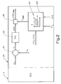
- FIG. 2 shows a schematic block diagram illustrating a lambda controller 20 according to the invention.
- the lambda controller is placed in the ECU 4.
- the term "control unit” will be used to denote the ECU 4 including the lambda controller 20.
- the lambda controller 20 comprises a difference amplifier or subtractor 21 in which a measured value of lambda ⁇ M is subtracted from a required value of lambda ⁇ R .
- the difference signal is transmitted to a PID controller 22 that calculates a nominal required adjustment in IVC timing for a subsequent combustion cycle and generates an adjustment signal ⁇ IVC.
- the adjustment signal ⁇ IVC may need to be corrected.
- control unit 4 comprises an IVC mode calculating section that is provided with an IVC mode selector.
- the mode selector determines if early intake valve closing IVC E or late intake valve closing IVC L timing is required for the subsequent combustion cycle based on the current IVC timing, output signals from a number of engine parameter sensors and the driver demand on the engine.
- the lambda controller 20 is provided with an IVC sensitivity determining section 23, arranged to determine intake valve closure sensitivity for the IVC timing for the subsequent cycle based on the calculated IVC mode and input signals representing measured values for engine speed n E and IVC timing. Based on the engine speed n E , current IVC timing and a possible change in early or late IVC timing, a sensitivity correction factor F CORR or sensitivity number is interpolated from a matrix 24 stored in the lambda controller 20. The start values for the vectors used in said matrix are calculated from differentiating the intake volume as a function of crank angle degree, as described in "Internal Combustion Engine Fundamentals" by John B. Heywood; McGraw-Hill, 1988; Chapter 2.2. By taking the engine speed into account, the accuracy of the calculations is improved.
- the engine combustion cycle may be switched at a point between early IVC (IVC E ) and late IVC (IVC L ) at any time, depending on the operating conditions.
- “early” generally means closing the intake valve before BDC and “late” means closing after BDC, i.e. pushing air back into the intake manifold.
- the switching point is the intake closure timing at which maximum filling of the combustion chamber is achieved. At low engine speeds the switching point between early and late occurs near BDC. However, at higher engine speeds said switching point will occur at 20 to 60 degrees after BDC. The position of the switching point in relation to the engine speed is determined by the matrix for the respective mode.
- This IVC mode signal is preferably, but not necessarily, a binary signal. If the IVC mode signal indicates that a mode switch between early and late IVC timing will occur between a current and a subsequent combustion cycle, then the polarity of the adjustment signal ⁇ IVC generated by the the PID controller must be changed. This is achieved by selecting a sensitivity correction factor F CORR or sensitivity number from different parts of the matrix 24 depending on the value of the mode signal. The said sensitivity correction factor or sensitivity number actually represents the inverted IVC sensitivity, but for control purposes a multiplication operation, as described below, is preferable.
- the lambda controller is provided with two separate matrices, whereby each matrix is associated with the IVC E or IVC L modes respectively.
- Figures 3A and 3B show schematic diagrams representing the variation of the sensitivity correction factor F CORR over crank angle ⁇ .
- Figure 3A shows the variation of the sensitivity correction factor F CORR from a relatively low to a relatively high positive value over a range of crank angles between 390 and 540 °, where BDC occurs at 540 °.
- Figure 3B shows the variation of the sensitivity correction factor F CORR from a relatively high to a relatively low negative value over a range of crank angles between 540 and 690 °, where BDC occurs at 540 °.
- the lambda controller 20 is further provided with a correcting section 25, arranged to calculate a corrected IVC adjustment signal ⁇ IVC CORR by multiplying said adjustment signal ⁇ IVC by a signal representing said correction factor F CORR .
- the corrected adjustment signal ⁇ IVC CORR output from the correcting section 25 is then transmitted to the section of the control unit 4 calculating IVC timing.
- the corrected adjustment signal ⁇ IVC CORR is added to the current demand for IVC timing and transmitted to the valve actuators.
Landscapes
- Engineering & Computer Science (AREA)
- Chemical & Material Sciences (AREA)
- Combustion & Propulsion (AREA)
- Mechanical Engineering (AREA)
- General Engineering & Computer Science (AREA)
- Output Control And Ontrol Of Special Type Engine (AREA)
- Electrical Control Of Air Or Fuel Supplied To Internal-Combustion Engine (AREA)
Abstract
- measuring a lambda value and determining a required change of the lambda value for a subsequent combustion cycle;
- generating an adjustment signal for adjusting IVC timing for a subsequent cycle based on the required change of the lambda value;
- determining if IVC timing will occur early or late with respect to a switching point at which maximum filling of the cylinder is achieved for said subsequent cycle, and
- changing the polarity of said signal if the signal causes a switch between early and late IVC timing.
Description
- The invention relates to a method and an arrangement for controlling an internal combustion engine provided with means for controlling the value of lambda by means of the intake valve timing, in particular the timing for intake valve closing.
- In previously proposed camless or other types of variable valve timing (WT) controlling apparatus, open-and-closure operation of engine valves, for example, an intake valve can arbitrarily be controlled using variably operated engine valve drive mechanisms and an intake air quantity induced into a corresponding engine cylinder is controlled by varying a valve closure timing of the intake valve. The intake valve closure may occur at a time before a piston reaches to an intake stroke bottom dead center as a latest valve closure timing, i.e. an early valve closure timing control. Similarly, an intake valve closure occurring at a time after a piston reaches to an intake stroke bottom dead center as a latest valve closure timing is termed a late valve closure timing control.
- Since such valve open-and-closure timing controlling apparatus as described above has an object of an improvement in a fuel consumption through a non-throttle dnve, the engine is basically operated with an air pressure within an intake air passage being equivalent to the atmospheric pressure. An air quantity to be induced into the cylinder is controlled by a cylinder volume at the time point of the closure of the intake valve. Such an arrangement is known from
EP 1 085 192. - The main problem to be solved by the invention is to improve the control of the amount of air inducted to the engine. The modern emission legislation requires high accuracy when it comes to controlling the exhaust lambda value (air/fuel ratio). There are two main methods of lambda control in an internal combustion engine. One is to vary the amount of injected fuel and the other is to vary the amount of induced air.
- The standard way of controlling the lambda value is by changing the injection time, or duty cycles, of the fuel injectors. One reason for selecting this variable is because it is in the fuel supply there are the biggest uncertainties, as the airflow through the intake conduit or manifold is normally measured quite accurately with a Hot Film Mass (HFM) sensor. To control the value of lambda by regulating the amount of induced air in a normal engine, provided with a camshaft, using the air intake throttle would require an electronic throttle, and even then the throttle response would be to slow.
- In an port injected camless engine on the other hand there is an uncertainty of fuel delivery of about ±5%, mainly depending on fuel viscosity and injector coil temperature for a given injection time. During transients there may be an additional influence from fuel condensed on the walls of the intake conduits. In this case the uncertainty of the amount of induced air is greater than that of the fuel delivery, depending on the relatively large effect of reflected pressure pulses and internal EGR. In this case, the amount of induced air is the actual amount of air delivered into the combustion chamber. One way to overcome this problem could be to control the amount of trapped air by adjusting the intake valve closing (IVC) from cycle to cycle. However, if the controller. parameters are tuned to function well in the area around 90 degrees after top dead centre (ATDC) the controller will be too slow around bottom dead centre (BDC).
- Hence, a problem to be solved in connection with the delivery of induced air is to provide a means for intake valve control that is sufficiently accurate and fast to allow control of the air fuel ratio. A further problem to be solved by the invention is to provide a control unit provided with a controller that may be used over the entire IVC timing range.
- The above problems are solved by a method, an arrangement and a computer readable storage device for controlling the value of lambda by adjusting closing timing of the inlet valve, according to
claims - The invention relates to a method for operating an internal combustion engine provided with at least one cylinder, said engine comprising a fuel injector, through which fuel is injected into a combustion chamber, for each cylinder and a piston in the engine cylinder whose action causes a mixture of air and fuel within the combustion chamber to be compressed. The invention can be implemented on spark ignited engines (SI) as well as engines with spark assisted compression ignition and autoignition, commonly known as homogenous charge compression ignition (HCCI) engines. The engine is preferably, but not necessarily, directed towards gasoline internal combustion engines.
- Each cylinder is provided with at least one inlet valve with variable valve timing per cylinder for admitting combustible gas and at least one exhaust valve preferably, but not necessarily, with variable valve timing per cylinder for exhausting combusted gases The intake and exhaust valves can be camless, controlled by a camshaft, or be operated by a combination of the two, e.g WT intake valves and camshaft driven exhaust valves A camshaft for WT can be of the cam profile switching (CPS) type. As the invention is mainly aimed at intake valve control, it is also possible to operate the exhaust valves by means of a conventional camshaft.
- A control unit is used for controlling fuel injection timing and quantity per combustion cycle injected through each fuel injector, as well as the valve timing of the inlet and outlet valves. A first sensor is provided for measuring a lambda value and at least one further sensor measures one or more engine operation parameters.
- When controlling the value of lambda by means of the intake valve timing, in particular the timing for intake valve closing (IVC), it is necessary to take the IVC sensitivity into consideration. The IVC sensitivity reaches a maximum for angles near 90 degrees after top dead centre (ATDC), when the piston speed is the highest. The definition of high IVC sensitivity is that for a small change in IVC, the amount of air trapped in the cylinder may vary significantly. The IVC sensitivity can be expressed as a function of the volume of inducted air and crank angle, in that:

V denotes volume and
θ denotes crank angle. - However, when choosing the IVC as the main parameter for lambda control, it may be necessary to correct the output of a conventional PID controller used to calculate the adjustment for the IVC timing, as the IVC sensitivity may vary significantly over the usable IVC range. A PID controller, where PID stands for Proportional-Integral-Derivative, is a conventional component in control units of this type, and will not be described in detail. The controller described in the embodiments below is a PID controller, but any type of conventional controller, such as a H-infinity controller or a pole-placement controller may be used. By determining a correction factor for the IVC timing, the effect of IVC sensitivity can be minimised. The correction factor is dependent on measured values of IVC and engine speed, but also on the IVC mode. If it is detected that a mode switch between early and late IVC timing will occur between a current and a subsequent combustion cycle, then the polarity of the adjustment signal must be changed. This will be described in further detail below and in connection with the attached figures.
- A preferred embodiment of the invention involves a method for adjusting the intake valve closing timing for air/fuel ratio (lambda) control. The control is preferably, but not necessarily, performed from cycle to cycle, by:
- measuring a lambda value and determining a required change of the lambda value for a subsequent combustion cycle;
- generating an adjustment signal for adjusting IVC timing for a subsequent cycle based on the required change of the lambda value;
- determining if IVC timing will occur early or late with respect to a switching point at which maximum filling of the cylinder is achieved for said subsequent cycle; and
- changing the polarity of said signal if it is determined that a switch will occur between early and late IVC timing.
- In the given examples, the expression "cycle-to-cycle" is defined as a subsequent cycle in the firing order of the engine. For instance, for a 5-cylinder engine with the firing order 1-2-4-5-3, the intake cycle of the first cylinder is followed by the intake cycle of the second cylinder, and so on. In this case the adjustment signal for adjusting IVC timing is generated for an immediately subsequent cycle. However, the invention can also be applied to the case when "cycle-to-cycle" refers to the subsequent intake cycle for the same cylinder, e.g. from
cylinder 1 tocylinder 1. - Note that although the intake valve closing can be adjusted from cycle-to-cycle, the measured value of lambda is dependent on the transport time of the exhaust gas from the cylinder to the sensor and subject to a time lag and response time inherent in the sensor. Hence, the value of lambda is not possible to control in real time, that is from cycle-to-cycle, but is adjusted in relation to a subsequent cycle, which may occur a number of cycles later Therefore difference should be made between the expression relating to a "subsequent cycle" in connection with lambda and IVC timing respectively.
- The signal for adjusting the IVC is generated by comparing a measured lambda value with a required value of lambda and processing the difference signal in a PID controller to calculate a nominal required adjustment in IVC timing (ΔIVC) for a subsequent cycle. The output from the PID controller is an adjustment signal representing the required change in IVC timing. The initial comparison is preferably done by subtracting a signal representing a required lambda value from a signal representing a measured lambda value.
- The polarity of the PID controller output will be changed when a switch between early and late IVC timing (IVCE, IVCL) is required for a subsequent combustion cycle. Determination of whether the said polarity of the IVC adjustment signal must be changed is achieved by:
- determining an IVC timing mode by acquiring a signal from a mode selector in the control unit , which selector determines said mode for the subsequent cycle depending on measured engine parameters;
- determining if the IVC timing for the subsequent cycle requires a switch between early and late IVC timing mode; and
- generating a correction signal indicative of a change in polarity if a switch is required.
- The signal acquired from the mode selector is preferably, but not necessarily, a binary signal.
- A corrected IVC adjustment signal may be achieved by multiplying said adjustment signal by said correction signal. The state of the signal from the mode selector determines the polarity of the correction signal.
- According to a further embodiment, the intake valve closure sensitivity for the IVC timing for a current cycle may be determined by selecting a sensitivity correction factor from a matrix, based on calculated IVC timing mode and measured valued for engine speed and IVC timing. The IVC timing mode is determined by acquiring a signal from a mode selector in the control unit, which selector determines said mode for the subsequent cycle depending on measured engine parameters. As stated above, the corrected IVC adjustment signal is obtained by multiplying said adjustment signal by said correction signal.
- The invention further relates to an internal combustion engine provided with at least one cylinder, as defined above. The engine is preferably, but not necessarily aspirated and port injected. According to a preferred embodiment, the engine control unit is arranged to adjust the closing timing of the inlet valve to control the air/fuel ratio (lambda), preferably, but not necessarily from cycle to cycle. The control unit is provided with:
- a lambda calculating section, arranged to calculate a required change of a lambda value for a subsequent combustion cycle;
- an IVC adjustment calculating section, arranged to calculate an adjustment signal for adjusting IVC timing for a subsequent cycle based on the required change of the lambda value;
- an IVC mode calculating section, arranged to calculate if the IVC timing for said subsequent cycle will occur early or late with respect to a switching point at which maximum filling of the cylinder is achieved for said subsequent cycle; and
- a polarity changing section, arranged to change the polarity of said signal if it is determined that a switch will occur between early and late IVC timing.
- The IVC adjustment calculating section may be arranged to calculate an adjustment signal for a subsequent cycle, which subsequent cycle can be either an immediately subsequent cycle or a subsequent cycle for the same cylinder.
- The IVC mode calculating section is provided with an IVC mode selector, which selector determines if early or late IVC timing is required for the subsequent cycle based on output signals from at least one further engine parameter sensor.
- The control unit is further provided with a IVC sensitivity determining section, arranged to determine intake valve closure sensitivity for the IVC timing for the subsequent cycle based on calculated IVC mode and measured values for engine speed and IVC timing by selecting a sensitivity correction factor from a matrix stored in the control unit.
- The lambda controller is also provided with a correcting section, arranged to calculate a corrected IVC adjustment signal by multiplying said adjustment signal by a signal representing said correction factor.
- The IVC adjustment calculating section may comprise a PID controller, arranged to process a difference signal from a lambda value comparator, or subtractor, and calculating said IVC adjustment signal.
- According to a further preferred embodiment, the invention relates to a computer readable storage device having stored therein data representing instructions executable by a computer to operate an internal combustion engine, the engine having a piston disposed in a cylinder to define a combustion chamber, intake valves for admitting fresh air into the cylinder, a fuel injector for injecting fuel into the combustion chamber, and exhaust valves for discharging exhaust gas resulting from combustion within the cylinder, wherein opening and closing timings of at least the intake valves are adjustable, the computer readable storage device comprising:
- instructions for adjusting opening and closing timings of at least the intake valves such that the piston reciprocates within the cylinder to perform an exhaust phase, an intake phase, a compression phase, and an expansion phase;
- instructions for measuring a lambda value and determining a required change of the lambda value for a subsequent combustion cycle;
- instructions for generating an adjustment signal for adjusting IVC timing for a subsequent cycle based on the required change of the lambda value;
- instructions for determining if IVC timing will occur early or late with respect to a switching point at which maximum filling of the cylinder is achieved for said subsequent cycle; and
- instructions for changing the polarity of said signal if it is determined that a switch will occur between early and late IVC timing.
- In the following text, the invention will be described in detail with reference to the attached drawings. These drawings are used for illustration only and do not in any way limit the scope of the invention. In the drawings:
- Figure 1
- shows a schematic internal combustion engine according to the invention;
- Figure 2
- shows a schematic block diagram illustrating a lambda controller according to the invention;
- Figure 3A
- shows a diagram illustrating IVC sensitivity over crank angle in early IVC;
- Figure 3B
- shows a diagram illustrating IVC sensitivity over crank angle in late IVC;
- Figure 1 shows a schematic illustration of an internal combustion engine according to the invention. The engine is provided with at least one
cylinder 1 and is provided with afuel injector 2 for port injection of fuel. Alternatively the cylinder is provided with a fuel injector 2', through which fuel is injected directly into acombustion chamber 3, for each cylinder. An electronic control unit 4 (ECU) controls fuel injection quantity per combustion cycle injected through each fuel injector. Apiston 5 in the engine cylinder has a compression action that causes a mixture of air and fuel within the combustion chamber to be compressed before ignition. The cylinder is provided with at least oneinlet valve 6 for admitting gas which includes fresh air into said cylinder and at least oneexhaust valve 7 for exhausting combusted gases from said cylinder. Air is supplied through anintake conduit 9 connected to an intake manifold, while exhaust gas is exhausted through anexhaust conduit 10. During spark ignition (SI) mode, the ignition of the fuel/air mixture is ignited by aspark plug 8. - The control unit receives signals from at least one sensor for measuring engine operation parameters, which sensors may include one or more of a combustion
chamber pressure sensor 11, an intakemanifold pressure sensor 12 and a λ-probe 13 for measuring the air-fuel ratio λ in theexhaust conduit 10, as well as sensors for intakeair mass flow 14,engine speed 15 and at least onefurther sensor 16, such as an intake air temperature sensor. Thecontrol unit 4 controls the intake andexhaust valves valve actuators - Figure 2 shows a schematic block diagram illustrating a
lambda controller 20 according to the invention. In this embodiment the lambda controller is placed in theECU 4. In the following text the term "control unit" will be used to denote theECU 4 including thelambda controller 20. Thelambda controller 20 comprises a difference amplifier orsubtractor 21 in which a measured value of lambda λM is subtracted from a required value of lambda λR. The difference signal is transmitted to aPID controller 22 that calculates a nominal required adjustment in IVC timing for a subsequent combustion cycle and generates an adjustment signal ΔIVC. - Depending on a possible change in operating mode for the subsequent combustion cycle with respect to the operating mode current combustion cycle, the adjustment signal ΔIVC may need to be corrected.
- For this purpose the
control unit 4 comprises an IVC mode calculating section that is provided with an IVC mode selector. The mode selector determines if early intake valve closing IVCE or late intake valve closing IVCL timing is required for the subsequent combustion cycle based on the current IVC timing, output signals from a number of engine parameter sensors and the driver demand on the engine. - In addition the
lambda controller 20 is provided with an IVCsensitivity determining section 23, arranged to determine intake valve closure sensitivity for the IVC timing for the subsequent cycle based on the calculated IVC mode and input signals representing measured values for engine speed nE and IVC timing. Based on the engine speed nE, current IVC timing and a possible change in early or late IVC timing, a sensitivity correction factor FCORR or sensitivity number is interpolated from amatrix 24 stored in thelambda controller 20. The start values for the vectors used in said matrix are calculated from differentiating the intake volume as a function of crank angle degree, as described in "Internal Combustion Engine Fundamentals" by John B. Heywood; McGraw-Hill, 1988; Chapter 2.2. By taking the engine speed into account, the accuracy of the calculations is improved. - In operation, the engine combustion cycle may be switched at a point between early IVC (IVCE) and late IVC (IVCL) at any time, depending on the operating conditions. In this context "early" generally means closing the intake valve before BDC and "late" means closing after BDC, i.e. pushing air back into the intake manifold. The switching point is the intake closure timing at which maximum filling of the combustion chamber is achieved. At low engine speeds the switching point between early and late occurs near BDC. However, at higher engine speeds said switching point will occur at 20 to 60 degrees after BDC. The position of the switching point in relation to the engine speed is determined by the matrix for the respective mode. A signal representing IVCE or IVCL mode, as selected by the
control unit 4 for the subsequent combustion cycle, is transmitted to the IVCsensitivity determining section 23 of thelambda controller 20. This IVC mode signal is preferably, but not necessarily, a binary signal. If the IVC mode signal indicates that a mode switch between early and late IVC timing will occur between a current and a subsequent combustion cycle, then the polarity of the adjustment signal ΔIVC generated by the the PID controller must be changed. This is achieved by selecting a sensitivity correction factor FCORR or sensitivity number from different parts of thematrix 24 depending on the value of the mode signal. The said sensitivity correction factor or sensitivity number actually represents the inverted IVC sensitivity, but for control purposes a multiplication operation, as described below, is preferable. - Alternatively, the lambda controller is provided with two separate matrices, whereby each matrix is associated with the IVCE or IVCL modes respectively.
- Figures 3A and 3B show schematic diagrams representing the variation of the sensitivity correction factor FCORR over crank angle θ. Figure 3A shows the variation of the sensitivity correction factor FCORR from a relatively low to a relatively high positive value over a range of crank angles between 390 and 540 °, where BDC occurs at 540 °. Figure 3B shows the variation of the sensitivity correction factor FCORR from a relatively high to a relatively low negative value over a range of crank angles between 540 and 690 °, where BDC occurs at 540 °.
- The
lambda controller 20 is further provided with a correctingsection 25, arranged to calculate a corrected IVC adjustment signal ΔIVCCORR by multiplying said adjustment signal ΔIVC by a signal representing said correction factor FCORR. The corrected adjustment signal ΔIVCCORR output from the correctingsection 25 is then transmitted to the section of thecontrol unit 4 calculating IVC timing. The corrected adjustment signal ΔIVCCORR is added to the current demand for IVC timing and transmitted to the valve actuators. - The invention is not limited to the embodiments described above, but may be varied freely within the scope of the appended claims.
Claims (17)
- A method for operating an internal combustion engine provided with at least one cylinder having at least one inlet valve with variable valve timing per cylinder for admitting combustible gas, at least one exhaust valve per cylinder for exhausting combusted gases, and a control unit that controls the valve timing of at least the inlet valves;
characterized by the method comprising adjusting closing timing of the inlet valve for air/fuel ratio control by:- measuring a lambda value and determining a required change of the lambda value for a subsequent combustion cycle;- generating an adjustment signal for adjusting inlet valve closing timing for a subsequent cycle based on the required change of the lambda value;- determining if inlet valve closing timing will occur early or late with respect to a switching point at which maximum filling of the cylinder is achieved for said subsequent cycle, andchanging the polarity of said signal if it is determined that a switch will occur between early and late inlet valve closing timing. - A method for operating an engine according to claim 1, characterized in that the signal for adjusting the inlet valve closing is generated by:- comparing a measured lambda value with a required value of lambda and passing the difference signal through a controller, and- calculating a nominal required change in inlet valve closing timing (ΔIVC) for a subsequent cycle.
- A method for operating an engine according to claim 2, characterized by changing the polarity of the controller output when a switch between early and late inlet valve closing timing (IVCE, IVCL) for a subsequent cycle is required.
- A method for operating an engine according to claim 2, characterized by generating an adjustment signal for adjusting inlet valve closing timing for an immediately subsequent cycle based on the required change of the lambda value.
- A method for operating an engine according to claim 1, characterized by generating an adjustment signal for adjusting inlet valve closing timing for a subsequent cycle for each cylinder based on the required change of the lambda value.
- A method for operating an engine according to claim 1, characterized by determining if the polarity of the inlet valve closing adjustment signal must be changed by:- determining an inlet valve closing timing mode by acquiring a signal from a mode selector in the control unit , which selector determines said mode for the subsequent cycle depending on measured engine parameters;- determining if the inlet valve closing timing for the subsequent cycle causes a switch between early and late inlet valve closing timing mode;- generating a correction signal indicative of a change in polarity if a switch is required.
- A method for operating an engine according to claim 1, characterized by determining if the polarity of the inlet valve closing adjustment signal must be changed by:- calculating the inlet valve closing timing for the subsequent cycle based on the current inlet valve closing timing and the adjustment signal (ΔIVC);- determining if the inlet valve closing timing for the subsequent cycle causes a switch between early and late inlet valve closing timing; and- generating a correction signal indicative of a change in polarity if a switch is required.
- A method for operating an engine according to claim 6 or 7, characterized by determining a corrected inlet valve closing adjustment signal by multiplying said adjustment signal by said correction signal.
- A method for operating an engine according to claim 1, characterized by determining intake valve closure sensitivity for the inlet valve closing timing for a current cycle by selecting a sensitivity correction factor from a matrix, based on measured valued for engine speed and inlet valve closing timing
- A method for operating an engine according to claim 9, characterized in determining an inlet valve closing timing mode by acquiring a signal from a mode selector in the control unit , which selector determines said mode for the subsequent cycle depending on measured engine parameters;
- A method for operating an engine according to claim 10, characterized in determining a corrected inlet valve closing adjustment signal by multiplying said adjustment signal by said correction signal.
- An internal combustion engine provided with at least one cylinder (1), comprising:- a fuel injector (2), through which fuel is injected into a combustion chamber, for each cylinder;- a piston (5) in the engine cylinder whose action causes a mixture of air and fuel within the combustion chamber to be compressed;- at least one inlet valve (6) with variable valve timing per cylinder for admitting combustible gas;- at least one exhaust valve (7) for exhausting combusted gases;- a control unit (4) that controls fuel injection quantity per combustion cycle injected through each fuel injector and the valve timing of at least the inlet valves;- a first sensor (13) is provided for measuring an air/fuel ratio; and- at least one further sensor for measuring an engine operation parameter;characterized in that the control unit is arranged to adjust the closing timing of the inlet valve to control the air/fuel ratio, whereby the control unit is provided with:- a lambda calculating section (21), arranged to calculate a required change of a lambda value (Δλ) for a subsequent combustion cycle;- an inlet valve closing adjustment calculating section (22), arranged to calculate an adjustment signal (ΔIVC) for adjusting inlet valve closing timing for a subsequent cycle based on the required change of the lambda value,- an inlet valve closing mode calculating section, arranged to calculate if the inlet valve closing timing for said subsequent cycle will occur early or late with respect to a switching point at which maximum filling of the cylinder is achieved for said subsequent cycle; and- a polarity changing section, arranged to change the polarity of said signal if it is determined that a switch will occur between early and late inlet valve closing timing.
- A combustion engine according to claim 12, characterized in the inlet valve closing mode calculating section is provided with an inlet valve closing mode selector, which selector determines if early or late inlet valve closing timing is required for the subsequent cycle.
- A combustion engine according to claim 12, characterized in the control unit is further provided with a inlet valve closing sensitivity determining section (23), arranged to determine intake valve closure sensitivity for the inlet valve closing timing for the subsequent cycle based on calculated inlet valve closing mode and measured values for engine speed and inlet valve closing timing by interpolating a sensitivity correction factor from at least one matrix stored in the control unit.
- A combustion engine according to claim 14, characterized in the control unit is further provided with a correcting section (25), arranged to calculate a corrected inlet valve closing adjustment signal (ΔIVCCORR) by multiplying said adjustment signal (ΔIVC) by a signal representing said correction factor (FCORR).
- A combustion engine according to claim 12, characterized in the inlet valve closing adjustment calculating section comprises a controller (22), arranged to process a difference signal (Δλ) from a lambda value comparator and calculating said inlet valve closing adjustment signal (ΔIVC).
- A computer readable storage device having stored therein data representing instructions executable by a computer to operate an internal combustion engine, the engine having a piston disposed in a cylinder to define a combustion chamber, intake valves for admitting fresh air into the cylinder, a fuel injector for injecting fuel into the combustion chamber, and exhaust valves for discharging exhaust gas resulting from combustion within the cylinder, wherein opening and closing timings of at least the intake valves are adjustable, the computer readable storage device comprising:- instructions for adjusting opening and closing timings of at least the intake valves such that the piston reciprocates within the cylinder to perform an exhaust phase, an intake phase, a compression phase, and an expansion phase;- instructions for measuring a lambda value and determining a required change of the lambda value for a subsequent combustion cycle;- instructions for generating an adjustment signal for adjusting inlet valve closing timing for a subsequent cycle based on the required change of the lambda value;- instructions for determining if inlet valve closing timing will occur early or late with respect to a switching point at which maximum filling of the cylinder is achieved for said subsequent cycle; and- instructions for changing the polarity of said signal if it is determined that a switch will occur between early and late inlet valve closing timing.
Priority Applications (2)
| Application Number | Priority Date | Filing Date | Title |
|---|---|---|---|
| DE60301052T DE60301052T2 (en) | 2003-03-21 | 2003-03-21 | Method and device for controlling the intake valve timing of an internal combustion engine |
| EP03006448A EP1460253B8 (en) | 2003-03-21 | 2003-03-21 | Method and arrangement for controlling the intake valve timing of an internal combustion engine |
Applications Claiming Priority (1)
| Application Number | Priority Date | Filing Date | Title |
|---|---|---|---|
| EP03006448A EP1460253B8 (en) | 2003-03-21 | 2003-03-21 | Method and arrangement for controlling the intake valve timing of an internal combustion engine |
Publications (3)
| Publication Number | Publication Date |
|---|---|
| EP1460253A1 true EP1460253A1 (en) | 2004-09-22 |
| EP1460253B1 EP1460253B1 (en) | 2005-07-20 |
| EP1460253B8 EP1460253B8 (en) | 2005-11-30 |
Family
ID=32798860
Family Applications (1)
| Application Number | Title | Priority Date | Filing Date |
|---|---|---|---|
| EP03006448A Expired - Lifetime EP1460253B8 (en) | 2003-03-21 | 2003-03-21 | Method and arrangement for controlling the intake valve timing of an internal combustion engine |
Country Status (2)
| Country | Link |
|---|---|
| EP (1) | EP1460253B8 (en) |
| DE (1) | DE60301052T2 (en) |
Cited By (2)
| Publication number | Priority date | Publication date | Assignee | Title |
|---|---|---|---|---|
| EP2031216A3 (en) * | 2007-08-31 | 2014-02-26 | Volkswagen Aktiengesellschaft | Method for operating a combustion engine |
| US9334818B2 (en) | 2013-03-22 | 2016-05-10 | Robert Bosch Gmbh | Mixed-mode combustion control |
Families Citing this family (1)
| Publication number | Priority date | Publication date | Assignee | Title |
|---|---|---|---|---|
| DE102010064344A1 (en) * | 2010-12-29 | 2012-07-05 | Volkswagen Ag | Method and device for controlling an internal combustion engine |
Citations (4)
| Publication number | Priority date | Publication date | Assignee | Title |
|---|---|---|---|---|
| DE3940752A1 (en) * | 1989-12-09 | 1991-06-13 | Bosch Gmbh Robert | METHOD FOR CONTROLLING AN OTTO ENGINE WITHOUT THROTTLE VALVE |
| US5377654A (en) * | 1992-11-12 | 1995-01-03 | Ford Motor Company | System using time resolved air/fuel sensor to equalize cylinder to cylinder air/fuel ratios with variable valve control |
| DE19530274A1 (en) * | 1995-08-17 | 1997-02-20 | Fev Motorentech Gmbh & Co Kg | Control system for IC engine |
| US6474323B1 (en) * | 1997-12-16 | 2002-11-05 | Servoject Products International | Optimized lambda and compression temperature control for compression ignition engines |
-
2003
- 2003-03-21 DE DE60301052T patent/DE60301052T2/en not_active Expired - Lifetime
- 2003-03-21 EP EP03006448A patent/EP1460253B8/en not_active Expired - Lifetime
Patent Citations (4)
| Publication number | Priority date | Publication date | Assignee | Title |
|---|---|---|---|---|
| DE3940752A1 (en) * | 1989-12-09 | 1991-06-13 | Bosch Gmbh Robert | METHOD FOR CONTROLLING AN OTTO ENGINE WITHOUT THROTTLE VALVE |
| US5377654A (en) * | 1992-11-12 | 1995-01-03 | Ford Motor Company | System using time resolved air/fuel sensor to equalize cylinder to cylinder air/fuel ratios with variable valve control |
| DE19530274A1 (en) * | 1995-08-17 | 1997-02-20 | Fev Motorentech Gmbh & Co Kg | Control system for IC engine |
| US6474323B1 (en) * | 1997-12-16 | 2002-11-05 | Servoject Products International | Optimized lambda and compression temperature control for compression ignition engines |
Cited By (2)
| Publication number | Priority date | Publication date | Assignee | Title |
|---|---|---|---|---|
| EP2031216A3 (en) * | 2007-08-31 | 2014-02-26 | Volkswagen Aktiengesellschaft | Method for operating a combustion engine |
| US9334818B2 (en) | 2013-03-22 | 2016-05-10 | Robert Bosch Gmbh | Mixed-mode combustion control |
Also Published As
| Publication number | Publication date |
|---|---|
| EP1460253B1 (en) | 2005-07-20 |
| EP1460253B8 (en) | 2005-11-30 |
| DE60301052D1 (en) | 2005-08-25 |
| DE60301052T2 (en) | 2006-06-01 |
Similar Documents
| Publication | Publication Date | Title |
|---|---|---|
| US7861690B2 (en) | Device and method for controlling internal combustion engine | |
| US7367318B2 (en) | Control system and control method of internal combustion engine | |
| US8046156B2 (en) | Control apparatus of internal combustion engine | |
| US6718957B2 (en) | Intelligent control to stabilize auto-ignition combustion without rapid pressure increase | |
| US5715794A (en) | Engine control system and method | |
| US7793637B2 (en) | Method for auto-ignition operation and computer readable storage device for use with an internal combustion engine | |
| US7004148B2 (en) | Control apparatus for internal combustion engine | |
| US20040159309A1 (en) | Knocking index value calculation device and calculation method thereof | |
| US6681729B2 (en) | Method and device for controlling a gas fill of cylinders of an internal combustion engine | |
| EP1437498B1 (en) | 4−STROKE ENGINE CONTROL DEVICE AND CONTROL METHOD | |
| EP1245811A2 (en) | Fuel metering method for an engine operating with controlled auto-ignition | |
| US8651088B2 (en) | Control apparatus for internal combustion engine | |
| JP2005248703A5 (en) | ||
| US6722342B2 (en) | Fuel injection control system and method for internal combustion engine as well as engine control unit | |
| CN1364216B (en) | Method for operating a multi-cylinder internal combustion engine | |
| EP1249593A2 (en) | Control system and method for a multi-cylinder internal combustion engine | |
| JP2007120392A (en) | Air-fuel ratio control device for internal combustion engine | |
| EP1435442B1 (en) | Internal combustion engine, method for auto-ignition operation and computer readable storage device | |
| EP1460253B1 (en) | Method and arrangement for controlling the intake valve timing of an internal combustion engine | |
| EP1211402A2 (en) | Internal EGR quantity estimation for controlling intake/exhaust valves and ignition timing | |
| JP2007231883A (en) | Air-fuel ratio control device for internal combustion engine | |
| US20070144481A1 (en) | Method for controlling the compression ignition mode of an internal combustion engine | |
| JP4338475B2 (en) | Method and apparatus for determining fuel wall membrane mass | |
| JP2004316545A (en) | Cylinder control device for compression ignition type internal combustion engine | |
| JP3800828B2 (en) | Cylinder residual gas amount detection device for variable valve engine |
Legal Events
| Date | Code | Title | Description |
|---|---|---|---|
| PUAI | Public reference made under article 153(3) epc to a published international application that has entered the european phase |
Free format text: ORIGINAL CODE: 0009012 |
|
| AK | Designated contracting states |
Kind code of ref document: A1 Designated state(s): AT BE BG CH CY CZ DE DK EE ES FI FR GB GR HU IE IT LI LU MC NL PT SE SI SK TR |
|
| AX | Request for extension of the european patent |
Extension state: AL LT LV MK RO |
|
| RIN1 | Information on inventor provided before grant (corrected) |
Inventor name: OESTBERG, CLAES |
|
| 17P | Request for examination filed |
Effective date: 20041022 |
|
| RIN1 | Information on inventor provided before grant (corrected) |
Inventor name: OESTBERG, CLAES |
|
| GRAP | Despatch of communication of intention to grant a patent |
Free format text: ORIGINAL CODE: EPIDOSNIGR1 |
|
| GRAS | Grant fee paid |
Free format text: ORIGINAL CODE: EPIDOSNIGR3 |
|
| GRAA | (expected) grant |
Free format text: ORIGINAL CODE: 0009210 |
|
| AKX | Designation fees paid |
Designated state(s): DE FR GB |
|
| AK | Designated contracting states |
Kind code of ref document: B1 Designated state(s): DE FR GB |
|
| REG | Reference to a national code |
Ref country code: GB Ref legal event code: FG4D |
|
| REF | Corresponds to: |
Ref document number: 60301052 Country of ref document: DE Date of ref document: 20050825 Kind code of ref document: P |
|
| REG | Reference to a national code |
Ref country code: SE Ref legal event code: TRGR |
|
| RBV | Designated contracting states (corrected) |
Designated state(s): DE GB SE |
|
| PLBE | No opposition filed within time limit |
Free format text: ORIGINAL CODE: 0009261 |
|
| STAA | Information on the status of an ep patent application or granted ep patent |
Free format text: STATUS: NO OPPOSITION FILED WITHIN TIME LIMIT |
|
| 26N | No opposition filed |
Effective date: 20060421 |
|
| EN | Fr: translation not filed | ||
| REG | Reference to a national code |
Ref country code: DE Ref legal event code: R082 Ref document number: 60301052 Country of ref document: DE Representative=s name: ISARPATENT, DE |
|
| REG | Reference to a national code |
Ref country code: DE Ref legal event code: R081 Ref document number: 60301052 Country of ref document: DE Owner name: VOLVO CAR CORPORATION, SE Free format text: FORMER OWNER: FORD GLOBAL TECHNOLOGIES, LLC (N.D.GES.D. STAATES DELAWARE), DEARBORN, MICH., US Effective date: 20120206 Ref country code: DE Ref legal event code: R082 Ref document number: 60301052 Country of ref document: DE Representative=s name: ISARPATENT PATENTANWAELTE BEHNISCH, BARTH, CHA, DE Effective date: 20120206 |
|
| REG | Reference to a national code |
Ref country code: GB Ref legal event code: 732E Free format text: REGISTERED BETWEEN 20120510 AND 20120516 |
|
| REG | Reference to a national code |
Ref country code: GB Ref legal event code: 732E Free format text: REGISTERED BETWEEN 20120517 AND 20120523 |
|
| PGFP | Annual fee paid to national office [announced via postgrant information from national office to epo] |
Ref country code: SE Payment date: 20130321 Year of fee payment: 11 Ref country code: DE Payment date: 20130320 Year of fee payment: 11 Ref country code: GB Payment date: 20130321 Year of fee payment: 11 |
|
| REG | Reference to a national code |
Ref country code: DE Ref legal event code: R119 Ref document number: 60301052 Country of ref document: DE |
|
| REG | Reference to a national code |
Ref country code: SE Ref legal event code: EUG |
|
| GBPC | Gb: european patent ceased through non-payment of renewal fee |
Effective date: 20140321 |
|
| PG25 | Lapsed in a contracting state [announced via postgrant information from national office to epo] |
Ref country code: SE Free format text: LAPSE BECAUSE OF NON-PAYMENT OF DUE FEES Effective date: 20140322 |
|
| REG | Reference to a national code |
Ref country code: DE Ref legal event code: R119 Ref document number: 60301052 Country of ref document: DE Effective date: 20141001 |
|
| PG25 | Lapsed in a contracting state [announced via postgrant information from national office to epo] |
Ref country code: GB Free format text: LAPSE BECAUSE OF NON-PAYMENT OF DUE FEES Effective date: 20140321 Ref country code: DE Free format text: LAPSE BECAUSE OF NON-PAYMENT OF DUE FEES Effective date: 20141001 |