EP1459914A1 - Securing of a bearing bracket of an axle assembly to a vehicle chassis - Google Patents
Securing of a bearing bracket of an axle assembly to a vehicle chassis Download PDFInfo
- Publication number
- EP1459914A1 EP1459914A1 EP04075822A EP04075822A EP1459914A1 EP 1459914 A1 EP1459914 A1 EP 1459914A1 EP 04075822 A EP04075822 A EP 04075822A EP 04075822 A EP04075822 A EP 04075822A EP 1459914 A1 EP1459914 A1 EP 1459914A1
- Authority
- EP
- European Patent Office
- Prior art keywords
- securing
- bearing bracket
- strip
- side plate
- chassis
- Prior art date
- Legal status (The legal status is an assumption and is not a legal conclusion. Google has not performed a legal analysis and makes no representation as to the accuracy of the status listed.)
- Granted
Links
- 239000006096 absorbing agent Substances 0.000 claims description 6
- 230000035939 shock Effects 0.000 claims description 6
- 239000000725 suspension Substances 0.000 description 9
- 239000011241 protective layer Substances 0.000 description 2
- 238000003466 welding Methods 0.000 description 2
- 238000005452 bending Methods 0.000 description 1
Images


Classifications
-
- B—PERFORMING OPERATIONS; TRANSPORTING
- B60—VEHICLES IN GENERAL
- B60G—VEHICLE SUSPENSION ARRANGEMENTS
- B60G7/00—Pivoted suspension arms; Accessories thereof
- B60G7/02—Attaching arms to sprung part of vehicle
-
- B—PERFORMING OPERATIONS; TRANSPORTING
- B60—VEHICLES IN GENERAL
- B60G—VEHICLE SUSPENSION ARRANGEMENTS
- B60G11/00—Resilient suspensions characterised by arrangement, location or kind of springs
- B60G11/02—Resilient suspensions characterised by arrangement, location or kind of springs having leaf springs only
- B60G11/10—Resilient suspensions characterised by arrangement, location or kind of springs having leaf springs only characterised by means specially adapted for attaching the spring to axle or sprung part of the vehicle
- B60G11/12—Links, pins, or bushes
-
- B—PERFORMING OPERATIONS; TRANSPORTING
- B60—VEHICLES IN GENERAL
- B60G—VEHICLE SUSPENSION ARRANGEMENTS
- B60G11/00—Resilient suspensions characterised by arrangement, location or kind of springs
- B60G11/32—Resilient suspensions characterised by arrangement, location or kind of springs having springs of different kinds
- B60G11/34—Resilient suspensions characterised by arrangement, location or kind of springs having springs of different kinds including leaf springs
- B60G11/46—Resilient suspensions characterised by arrangement, location or kind of springs having springs of different kinds including leaf springs and also fluid springs
- B60G11/465—Resilient suspensions characterised by arrangement, location or kind of springs having springs of different kinds including leaf springs and also fluid springs with a flexible wall
-
- B—PERFORMING OPERATIONS; TRANSPORTING
- B60—VEHICLES IN GENERAL
- B60G—VEHICLE SUSPENSION ARRANGEMENTS
- B60G2200/00—Indexing codes relating to suspension types
- B60G2200/30—Rigid axle suspensions
- B60G2200/31—Rigid axle suspensions with two trailing arms rigidly connected to the axle
-
- B—PERFORMING OPERATIONS; TRANSPORTING
- B60—VEHICLES IN GENERAL
- B60G—VEHICLE SUSPENSION ARRANGEMENTS
- B60G2204/00—Indexing codes related to suspensions per se or to auxiliary parts
- B60G2204/10—Mounting of suspension elements
- B60G2204/12—Mounting of springs or dampers
- B60G2204/121—Mounting of leaf springs
-
- B—PERFORMING OPERATIONS; TRANSPORTING
- B60—VEHICLES IN GENERAL
- B60G—VEHICLE SUSPENSION ARRANGEMENTS
- B60G2204/00—Indexing codes related to suspensions per se or to auxiliary parts
- B60G2204/10—Mounting of suspension elements
- B60G2204/14—Mounting of suspension arms
- B60G2204/143—Mounting of suspension arms on the vehicle body or chassis
-
- B—PERFORMING OPERATIONS; TRANSPORTING
- B60—VEHICLES IN GENERAL
- B60G—VEHICLE SUSPENSION ARRANGEMENTS
- B60G2204/00—Indexing codes related to suspensions per se or to auxiliary parts
- B60G2204/40—Auxiliary suspension parts; Adjustment of suspensions
- B60G2204/43—Fittings, brackets or knuckles
- B60G2204/4302—Fittings, brackets or knuckles for fixing suspension arm on the vehicle body or chassis
-
- B—PERFORMING OPERATIONS; TRANSPORTING
- B60—VEHICLES IN GENERAL
- B60G—VEHICLE SUSPENSION ARRANGEMENTS
- B60G2206/00—Indexing codes related to the manufacturing of suspensions: constructional features, the materials used, procedures or tools
- B60G2206/01—Constructional features of suspension elements, e.g. arms, dampers, springs
- B60G2206/60—Subframe construction
- B60G2206/601—Hanger bracket
Definitions
- the invention relates to a securing of a bearing bracket of an axle assembly to a vehicle chassis.
- bearing bracket of this type which is also known as a spring carrier arm
- the bearing bracket is often secured to the chassis by securing the side plates to one another and to the chassis beam with clamping force at the top side of the bearing bracket by means of ten or more bolted connections. This large number of bolted connections is undesirable.
- NL 1018772 shows a securing in which the securing regions of separate side plates of the bearing bracket are secured to one another and to a vertical surface of a chassis beam by means of bolts.
- the securing strip has a part which is clamped between the side plates of the securing bracket.
- One of the side plates is clamped between the vertical surface of the chassis beam and the securing strip.
- the securing strip has end regions which are connected to the vertical surface of the chassis beam.
- bearing brackets in which the side plates are not connected to one another at the top side are often also used. These bearing brackets generally involve direct welding to a chassis beam. It is desirable for this welding of the bearing bracket to be carried out while the chassis is being welded together, since a protective layer is then applied to the chassis, and this protective layer would otherwise be damaged by the bearing bracket subsequently being welded in place.
- One drawback of the welded brackets is that the chassis is less easy to stack for transport, since the bearing brackets project at the underside.
- One advantage is that the securing according to the invention can be used for bearing brackets with two side plates which do not have to be clamped together.
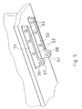
- Fig. 1 diagrammatically depicts a wheel axle suspension of an axle set of a vehicle.
- the wheel axle is denoted by reference numeral 1.
- the wheel axle 1, which has one or more wheels fitted to both its ends, is illustrated as a round hollow axle, but may also be an axle with a square or other shape of cross section.
- the wheel axle suspension comprises a bearing bracket 3 which is secured to a chassis component, in this case a chassis beam 2.
- the chassis beam 2 is in this example designed as an I profiled section with a bottom flange 2a and a top flange 2b, the bearing bracket 3 being fitted to the bottom surface 10 of the bottom flange 2a.
- the wheel axle suspension furthermore comprises a carrier arm 4, which is pivotably secured to the bearing bracket 3, for the wheel axle 1.
- the carrier arm 4 extends in the longitudinal direction of the vehicle.
- the wheel axle is secured to the carrier arm 4 in a known way by means of a clamp 5.
- the carrier arm 4 is secured to the bearing bracket 3 by a securing bolt 6.
- an end section 7 of the bearing arm 4 extends beyond the wheel axle 1.
- a gas spring 8 is arranged between the end section 7 and the chassis beam 2.
- Fig. 2 shows a perspective view, from below, of the chassis beam 2.
- the bottom flange 2a has a downwardly facing horizontal surface 10.
- Two separate securing strips 21 and 22 are welded to the horizontal surface 10. It is also possible for two securing strips, which are connected to one another by means of a connecting piece, to be welded to the horizontal surface 10. In this context, consideration may be given, for example, to a strip which is bent into a U shape from a single piece, in which case the limbs of the U form the securing strips.
- the securing strips 21, 22 are provided with securing holes 23.
- Fig. 3 shows how a bearing bracket comprising two separate side plates 11 and 12 bear, by means of respective securing regions 11a and 12a, against the securing strips 21 and 22, respectively.
- the securing regions 11a, 12a are provided with securing holes 13 (cf. also Fig. 1).
- the securing region 11a, 12a of the side plate 11, 12 is placed against the securing strip 21, 22 in such a manner that the securing holes 13 and the securing holes 23 are aligned with one another and a bolt can be fitted through them in order to connect the side plate and the securing strip to one another.
- the top edge of the side plates 11, 12 may bear completely or partially against the horizontal surface 10, but it is also possible for the side plates 11, 12 to be arranged in such a manner that the top edge is not in contact with the horizontal surface 10.
- Fig. 4 shows another embodiment of the wheel axle suspension.
- the components which correspond to the wheel axle suspension shown in Fig. 1 are denoted by identical reference numerals.
- the bearing bracket 3 also has two side plates 41, 42 (cf. Fig. 6), in which, in addition to the securing holes 13, there is also a securing hole for the bolt 40 which is used to secure the shock absorber 9 to the bearing bracket 3.
- the side plates 41 of the bearing bracket 3 are fitted onto securing strips, which in Fig. 5 are denoted by 51 and 52.
- the securing strips 51 and 52 have securing holes 53 which are similar to the securing holes 23 shown in Fig. 2.
- Lugs 57 which are higher than the remainder of the securing strips 51, 52 are arranged at one end of the securing strips 51, 52.
- a securing hole 56 In the lugs 57 there is a securing hole 56, through which the bolt 40 of the shock absorber 9 can be fitted.
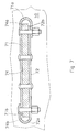
- Fig. 6 shows, partially in cross section, a bottom view of the embodiment shown in Fig. 4.
- Fig. 6 shows the securing strips 51 and 52 which are welded to the flange surface 10.
- the shock absorber 9 and the associated bolt 40 can also be seen.
- the side plate 41 is bent around the two end edges 51a and 51b of the securing strip 51 at the end regions 41a and 41b. As a result, the side plate 41 has parts 41c and 41d which engage on an inner side of the securing strip 51 and another part 41e which engages on the other side of the securing strip 51. At the end regions 42a and 42b, the side plate 42 is bent around the two end edges 52a and 52b of the securing strip 52. As a result, the side plate 42 has parts 42c and 42d which engage on an inner side of the securing strip 52 and another part 42e which engages on the other side of the securing strip 52.
- the bearing bracket 73 has two side plates 71 and 72.
- a single securing strip 74 is attached to the horizontal surface 10 of the chassis beam 2.
- the securing region of one side plate 71 bears against one side of the securing strip 74, and the securing region of the other side plate 72 bears against the other side of the securing strip 74.
- One end region 71a of the side plate 71 is bent around an end edge 74a of the strip 74 and partially laid over the plate 72.
- An end region 72a of the side plate 72 is bent over in the same way.
- an end region 72b of the side plate 72 is clamped between two parts of the side plate 71 and the securing strip 74.
- an end region 71b of the side plate 71 is clamped between two parts of the side plate 72 and the securing strip 74.
- This form of clamping gives rise to additional frictional surfaces, so that it is possible to provide better resistance to a moment of rotation acting on the bearing bracket 73.
Landscapes
- Engineering & Computer Science (AREA)
- Mechanical Engineering (AREA)
- Vehicle Body Suspensions (AREA)
- Body Structure For Vehicles (AREA)
Abstract
Description
- The invention relates to a securing of a bearing bracket of an axle assembly to a vehicle chassis.
- Numerous embodiments of a bearing bracket of this type, which is also known as a spring carrier arm, are known. The bearing bracket is often secured to the chassis by securing the side plates to one another and to the chassis beam with clamping force at the top side of the bearing bracket by means of ten or more bolted connections. This large number of bolted connections is undesirable.
- NL 1018772 shows a securing in which the securing regions of separate side plates of the bearing bracket are secured to one another and to a vertical surface of a chassis beam by means of bolts. The securing strip has a part which is clamped between the side plates of the securing bracket. One of the side plates is clamped between the vertical surface of the chassis beam and the securing strip. The securing strip has end regions which are connected to the vertical surface of the chassis beam.
- In practice, bearing brackets in which the side plates are not connected to one another at the top side are often also used. These bearing brackets generally involve direct welding to a chassis beam. It is desirable for this welding of the bearing bracket to be carried out while the chassis is being welded together, since a protective layer is then applied to the chassis, and this protective layer would otherwise be damaged by the bearing bracket subsequently being welded in place. One drawback of the welded brackets is that the chassis is less easy to stack for transport, since the bearing brackets project at the underside.
- Furthermore, there are numerous available designs of the bearing bracket. When the bearing bracket is being welded to the chassis, the drawback arises that the design of the bearing bracket which is welded to the chassis determines the specific design of the chassis. In principle, therefore, there is a specific chassis for each type of bearing bracket, with the result that there is less freedom of choice during subsequent assembly of the vehicle, and the vehicle manufacturer therefore has less flexibility.
- It is an object of the invention to provide an improved securing for a bearing bracket.
- This object is achieved by a securing in accordance with claim 1.
- One advantage is that the securing according to the invention can be used for bearing brackets with two side plates which do not have to be clamped together.
- Preferred embodiments of the securing according to the invention are given in the subclaims.
- The invention will be explained in more detail with reference to the drawing, in which:
- Fig. 1 diagrammatically depicts a wheel axle suspension of an axle set of a vehicle,
- Fig. 2 shows a perspective view, obliquely from below, of a chassis beam with securing strips of the wheel axle suspension shown in Fig. 1,
- Fig. 3 shows the chassis beam from Fig. 2 with a bearing bracket secured to it in accordance with the invention,
- Fig. 4 diagrammatically depicts a wheel axle suspension of an axle set of a vehicle provided with a shock absorber,
- Fig. 5 shows a perspective view, obliquely from below, of a chassis beam with securing strips of the wheel axle suspension shown in Fig. 4,
- Fig. 6 shows the chassis beam from Fig. 5 with a bearing bracket secured to it in accordance with the invention,
- Fig. 7 shows a sectional view from below of a chassis beam with a bearing bracket fitted to it in a different way in accordance with the invention.
- Fig. 1 diagrammatically depicts a wheel axle suspension of an axle set of a vehicle. The wheel axle is denoted by reference numeral 1. The wheel axle 1, which has one or more wheels fitted to both its ends, is illustrated as a round hollow axle, but may also be an axle with a square or other shape of cross section.
- The wheel axle suspension comprises a
bearing bracket 3 which is secured to a chassis component, in this case achassis beam 2. Thechassis beam 2 is in this example designed as an I profiled section with abottom flange 2a and atop flange 2b, thebearing bracket 3 being fitted to thebottom surface 10 of thebottom flange 2a. - The wheel axle suspension furthermore comprises a
carrier arm 4, which is pivotably secured to thebearing bracket 3, for the wheel axle 1. Thecarrier arm 4 extends in the longitudinal direction of the vehicle. The wheel axle is secured to thecarrier arm 4 in a known way by means of aclamp 5. - The
carrier arm 4 is secured to thebearing bracket 3 by a securingbolt 6. In the embodiment illustrated, anend section 7 of thebearing arm 4 extends beyond the wheel axle 1. Agas spring 8 is arranged between theend section 7 and thechassis beam 2. - The way in which the
bearing bracket 3 is secured to thechassis beam 2 will be explained in more detail with reference to Figs. 2 and 3. Fig. 2 shows a perspective view, from below, of thechassis beam 2. Thebottom flange 2a has a downwardly facinghorizontal surface 10. Twoseparate securing strips horizontal surface 10. It is also possible for two securing strips, which are connected to one another by means of a connecting piece, to be welded to thehorizontal surface 10. In this context, consideration may be given, for example, to a strip which is bent into a U shape from a single piece, in which case the limbs of the U form the securing strips. Thesecuring strips holes 23. - Fig. 3 shows how a bearing bracket comprising two
separate side plates regions securing strips securing regions securing region side plate securing strip holes 13 and the securingholes 23 are aligned with one another and a bolt can be fitted through them in order to connect the side plate and the securing strip to one another. The top edge of theside plates horizontal surface 10, but it is also possible for theside plates horizontal surface 10. - Fig. 4 shows another embodiment of the wheel axle suspension. The components which correspond to the wheel axle suspension shown in Fig. 1 are denoted by identical reference numerals. In this embodiment, there is a
shock absorber 9 arranged between thecarrier arm 4 and thebearing bracket 3. In this embodiment, thebearing bracket 3 also has twoside plates 41, 42 (cf. Fig. 6), in which, in addition to the securingholes 13, there is also a securing hole for thebolt 40 which is used to secure the shock absorber 9 to thebearing bracket 3. In this embodiment too, theside plates 41 of thebearing bracket 3 are fitted onto securing strips, which in Fig. 5 are denoted by 51 and 52. The securingstrips holes 53 which are similar to the securingholes 23 shown in Fig. 2.Lugs 57 which are higher than the remainder of the securingstrips strips lugs 57 there is asecuring hole 56, through which thebolt 40 of theshock absorber 9 can be fitted. - Fig. 6 shows, partially in cross section, a bottom view of the embodiment shown in Fig. 4. Fig. 6 shows the
securing strips flange surface 10. The shock absorber 9 and the associatedbolt 40 can also be seen. - The
side plate 41 is bent around the twoend edges securing strip 51 at theend regions side plate 41 hasparts securing strip 51 and anotherpart 41e which engages on the other side of thesecuring strip 51. At theend regions side plate 42 is bent around the twoend edges securing strip 52. As a result, theside plate 42 has parts 42c and 42d which engage on an inner side of thesecuring strip 52 and anotherpart 42e which engages on the other side of thesecuring strip 52. Bending theside plates side plates bearing bracket 3. - In another embodiment, a cross section through which at the level of the securing region is shown in Fig. 7, the bearing bracket 73 has two
side plates single securing strip 74 is attached to thehorizontal surface 10 of thechassis beam 2. The securing region of oneside plate 71 bears against one side of the securingstrip 74, and the securing region of theother side plate 72 bears against the other side of the securingstrip 74. - One
end region 71a of theside plate 71 is bent around anend edge 74a of thestrip 74 and partially laid over theplate 72. Anend region 72a of theside plate 72 is bent over in the same way. As a result, in the vicinity of theend edge 74a of the securingstrip 74, anend region 72b of theside plate 72 is clamped between two parts of theside plate 71 and the securingstrip 74. In the same way, in the vicinity of theother end edge 74b of the securingstrip 74, anend region 71b of theside plate 71 is clamped between two parts of theside plate 72 and the securingstrip 74. This form of clamping gives rise to additional frictional surfaces, so that it is possible to provide better resistance to a moment of rotation acting on the bearing bracket 73. - The above text has in each case described a bearing bracket with two separate side plates. It should be understood that the invention also relates to embodiments in which the bearing bracket has side plates which are connected to one another, for example by an intermediate plate.
Claims (8)
- Securing of a bearing bracket of an axle assembly to a chassis of a vehicle, which bearing bracket comprises two side plates which each have a securing region which is provided with holes through which bolts or other securing means fit in order to secure the side plates to a chassis component of the vehicle, wherein one or more securing strips with of a top side are fixed to a horizontal surface of the chassis component, and each side plate in each case being secured to a securing strip in such a manner that the securing region of the side plate is in each case arranged against a side face of the securing strip.
- Securing according to claim 1, characterized in that two separate securing strips or two securing strips which are connected to one another by means of a connecting piece are attached to the chassis component in order in each case to be secured to one of the side plates of the bearing bracket.
- Securing according to claim 1 or 2, characterized in that the securing region of each side plate has a part which engages on one side of the securing strip and another part which engages on the other side of the securing strip.
- Securing according to claim 3, characterized in that the side plate has a bent-over part which is bent around an end edge of the securing strip.
- Securing according to claim 3 or 4, characterized in that the side plate has two bent-over parts, which are respectively bent around two end edges of the securing strip.
- Securing according to one of the preceding claims, characterized in that in the securing strip there are cutouts which correspond to the holes in the side plates.
- Securing according to one of the preceding claims, characterized in that the securing strip is welded to the horizontal surface of the chassis component.
- Securing according to one of the preceding claims, characterized in that in the securing strip there is a securing hole for securing a shock absorber.
Applications Claiming Priority (2)
| Application Number | Priority Date | Filing Date | Title |
|---|---|---|---|
| NL1022948A NL1022948C2 (en) | 2003-03-17 | 2003-03-17 | Attaching a support bracket of an axle assembly to a vehicle chassis. |
| NL1022948 | 2003-03-17 |
Publications (2)
| Publication Number | Publication Date |
|---|---|
| EP1459914A1 true EP1459914A1 (en) | 2004-09-22 |
| EP1459914B1 EP1459914B1 (en) | 2011-06-08 |
Family
ID=32822944
Family Applications (1)
| Application Number | Title | Priority Date | Filing Date |
|---|---|---|---|
| EP04075822A Expired - Lifetime EP1459914B1 (en) | 2003-03-17 | 2004-03-12 | Securing of a bearing bracket of an axle assembly to a vehicle chassis |
Country Status (3)
| Country | Link |
|---|---|
| EP (1) | EP1459914B1 (en) |
| AT (1) | ATE512010T1 (en) |
| NL (1) | NL1022948C2 (en) |
Cited By (4)
| Publication number | Priority date | Publication date | Assignee | Title |
|---|---|---|---|---|
| EP2106934A1 (en) | 2008-03-31 | 2009-10-07 | Weweler Nederland N.V. | Hinging arrangement for a wheel axle suspension |
| WO2011119020A1 (en) | 2010-03-25 | 2011-09-29 | Weweler Nederland B.V. | Trailing arm mounting bracket |
| WO2017036875A1 (en) * | 2015-09-03 | 2017-03-09 | Saf-Holland Gmbh | Bearing block |
| WO2017178602A1 (en) * | 2016-04-15 | 2017-10-19 | Saf-Holland Gmbh | Bearing block unit |
Citations (6)
| Publication number | Priority date | Publication date | Assignee | Title |
|---|---|---|---|---|
| US2901240A (en) * | 1955-12-12 | 1959-08-25 | Tyman H Fikse | Vehicle suspension system |
| EP0325002A1 (en) * | 1988-01-07 | 1989-07-26 | Weweler N.V. | Connecting stucture for connecting a spring axle suspension to a vehicle chassis |
| JPH06270625A (en) * | 1993-03-22 | 1994-09-27 | Nissan Shatai Co Ltd | Structure of suspension link supporting part |
| EP0995664A1 (en) * | 1998-10-23 | 2000-04-26 | Weweler Nederland N.V. | Axle suspension for a vehicle with air spring system |
| US20020130480A1 (en) * | 2001-03-14 | 2002-09-19 | Vandenberg Ervin | Variable compliance pivot assembly and suspension system for use therewith |
| NL1018772C1 (en) * | 2001-08-16 | 2003-02-18 | Weweler Nv | Attaching a support bracket of an axle assembly to a vehicle chassis. |
-
2003
- 2003-03-17 NL NL1022948A patent/NL1022948C2/en not_active IP Right Cessation
-
2004
- 2004-03-12 EP EP04075822A patent/EP1459914B1/en not_active Expired - Lifetime
- 2004-03-12 AT AT04075822T patent/ATE512010T1/en not_active IP Right Cessation
Patent Citations (7)
| Publication number | Priority date | Publication date | Assignee | Title |
|---|---|---|---|---|
| US2901240A (en) * | 1955-12-12 | 1959-08-25 | Tyman H Fikse | Vehicle suspension system |
| EP0325002A1 (en) * | 1988-01-07 | 1989-07-26 | Weweler N.V. | Connecting stucture for connecting a spring axle suspension to a vehicle chassis |
| JPH06270625A (en) * | 1993-03-22 | 1994-09-27 | Nissan Shatai Co Ltd | Structure of suspension link supporting part |
| EP0995664A1 (en) * | 1998-10-23 | 2000-04-26 | Weweler Nederland N.V. | Axle suspension for a vehicle with air spring system |
| US20020130480A1 (en) * | 2001-03-14 | 2002-09-19 | Vandenberg Ervin | Variable compliance pivot assembly and suspension system for use therewith |
| NL1018772C1 (en) * | 2001-08-16 | 2003-02-18 | Weweler Nv | Attaching a support bracket of an axle assembly to a vehicle chassis. |
| EP1284208A2 (en) * | 2001-08-16 | 2003-02-19 | Weweler Nederland B.V. | Arrangement for attaching a bearing bracket of an axle assembly to a vehicle chassis |
Non-Patent Citations (1)
| Title |
|---|
| PATENT ABSTRACTS OF JAPAN vol. 018, no. 682 (M - 1729) 22 December 1994 (1994-12-22) * |
Cited By (7)
| Publication number | Priority date | Publication date | Assignee | Title |
|---|---|---|---|---|
| EP2106934A1 (en) | 2008-03-31 | 2009-10-07 | Weweler Nederland N.V. | Hinging arrangement for a wheel axle suspension |
| WO2009123437A1 (en) * | 2008-03-31 | 2009-10-08 | Weweler Nederland B.V. | Hinging arrangement for a wheel axle suspension |
| US8448964B2 (en) | 2008-03-31 | 2013-05-28 | Vdl Weweler B.V. | Hinging arrangement for a wheel axle suspension |
| WO2011119020A1 (en) | 2010-03-25 | 2011-09-29 | Weweler Nederland B.V. | Trailing arm mounting bracket |
| US8960694B2 (en) | 2010-03-25 | 2015-02-24 | Vdl Weweler B.V. | Trailing arm mounting bracket |
| WO2017036875A1 (en) * | 2015-09-03 | 2017-03-09 | Saf-Holland Gmbh | Bearing block |
| WO2017178602A1 (en) * | 2016-04-15 | 2017-10-19 | Saf-Holland Gmbh | Bearing block unit |
Also Published As
| Publication number | Publication date |
|---|---|
| NL1022948C2 (en) | 2004-09-20 |
| EP1459914B1 (en) | 2011-06-08 |
| ATE512010T1 (en) | 2011-06-15 |
Similar Documents
| Publication | Publication Date | Title |
|---|---|---|
| JP7172875B2 (en) | frame car body structure | |
| AU716460B2 (en) | Means for and method of mounting a suspension member to an axle housing | |
| EP2006129A1 (en) | Spring carrier arm | |
| JP2007186051A (en) | Vehicle under-run protector mounting structure | |
| US6866333B2 (en) | Vehicle front body structure | |
| EP1459914B1 (en) | Securing of a bearing bracket of an axle assembly to a vehicle chassis | |
| JP2005313829A (en) | Engine mount structure | |
| US8006990B1 (en) | Spring hanger and method for attachment | |
| US6941634B2 (en) | Method for attaching axles to a leaf springs on hydraulic disc brake vehicles | |
| EP1481824B1 (en) | Axle suspension | |
| US20060181047A1 (en) | Trailing arm for a vehicle suspension | |
| EP1284208B1 (en) | Arrangement for attaching a bearing bracket of an axle assembly to a vehicle chassis | |
| EP1086836A1 (en) | Bearing bracket for attaching an axle assembly to the chassis of a vehicle | |
| JP2002130360A (en) | Knuckle bracket structure of hydraulic shock absorber | |
| EP1508459A1 (en) | Connection between round vehicle axle and suspension arm | |
| EP1762405B1 (en) | Vehicle suspensions | |
| US6109632A (en) | Front wheel double suspension triangle frame for four-wheel drive automobile | |
| GB2446255A (en) | A cast crossmember centre section | |
| EP1580044A1 (en) | Connection between a wheel axle of a vehicle and a said wheel axle carrying trailing arm | |
| US20020074762A1 (en) | Attachment of a vehicle axle to an axle suspension | |
| JP2001072377A5 (en) | ||
| EP1380448A1 (en) | Device for securing a wheel axle to the chassis of a vehicle | |
| JP3165944B2 (en) | Independent suspension | |
| GB2528735A (en) | A control arm of a suspension | |
| US20150321513A1 (en) | Torque Rod Bracket for Mounting a Torque Rod on a Housing of a Tag Axle |
Legal Events
| Date | Code | Title | Description |
|---|---|---|---|
| PUAI | Public reference made under article 153(3) epc to a published international application that has entered the european phase |
Free format text: ORIGINAL CODE: 0009012 |
|
| AK | Designated contracting states |
Kind code of ref document: A1 Designated state(s): AT BE BG CH CY CZ DE DK EE ES FI FR GB GR HU IE IT LI LU MC NL PL PT RO SE SI SK TR |
|
| AX | Request for extension of the european patent |
Extension state: AL HR LT LV MK |
|
| 17P | Request for examination filed |
Effective date: 20050223 |
|
| AKX | Designation fees paid |
Designated state(s): AT BE BG CH CY CZ DE DK EE ES FI FR GB GR HU IE IT LI LU MC NL PL PT RO SE SI SK TR |
|
| 17Q | First examination report despatched |
Effective date: 20091217 |
|
| GRAP | Despatch of communication of intention to grant a patent |
Free format text: ORIGINAL CODE: EPIDOSNIGR1 |
|
| GRAS | Grant fee paid |
Free format text: ORIGINAL CODE: EPIDOSNIGR3 |
|
| RAP1 | Party data changed (applicant data changed or rights of an application transferred) |
Owner name: VDL WEWELER B.V. |
|
| GRAA | (expected) grant |
Free format text: ORIGINAL CODE: 0009210 |
|
| AK | Designated contracting states |
Kind code of ref document: B1 Designated state(s): AT BE BG CH CY CZ DE DK EE ES FI FR GB GR HU IE IT LI LU MC NL PL PT RO SE SI SK TR |
|
| REG | Reference to a national code |
Ref country code: GB Ref legal event code: FG4D |
|
| REG | Reference to a national code |
Ref country code: CH Ref legal event code: EP |
|
| REG | Reference to a national code |
Ref country code: IE Ref legal event code: FG4D |
|
| REG | Reference to a national code |
Ref country code: DE Ref legal event code: R096 Ref document number: 602004032936 Country of ref document: DE Effective date: 20110721 |
|
| REG | Reference to a national code |
Ref country code: NL Ref legal event code: VDEP Effective date: 20110608 |
|
| PG25 | Lapsed in a contracting state [announced via postgrant information from national office to epo] |
Ref country code: SE Free format text: LAPSE BECAUSE OF FAILURE TO SUBMIT A TRANSLATION OF THE DESCRIPTION OR TO PAY THE FEE WITHIN THE PRESCRIBED TIME-LIMIT Effective date: 20110608 |
|
| PG25 | Lapsed in a contracting state [announced via postgrant information from national office to epo] |
Ref country code: ES Free format text: LAPSE BECAUSE OF FAILURE TO SUBMIT A TRANSLATION OF THE DESCRIPTION OR TO PAY THE FEE WITHIN THE PRESCRIBED TIME-LIMIT Effective date: 20110919 Ref country code: GR Free format text: LAPSE BECAUSE OF FAILURE TO SUBMIT A TRANSLATION OF THE DESCRIPTION OR TO PAY THE FEE WITHIN THE PRESCRIBED TIME-LIMIT Effective date: 20110909 Ref country code: AT Free format text: LAPSE BECAUSE OF FAILURE TO SUBMIT A TRANSLATION OF THE DESCRIPTION OR TO PAY THE FEE WITHIN THE PRESCRIBED TIME-LIMIT Effective date: 20110608 Ref country code: SI Free format text: LAPSE BECAUSE OF FAILURE TO SUBMIT A TRANSLATION OF THE DESCRIPTION OR TO PAY THE FEE WITHIN THE PRESCRIBED TIME-LIMIT Effective date: 20110608 Ref country code: CY Free format text: LAPSE BECAUSE OF FAILURE TO SUBMIT A TRANSLATION OF THE DESCRIPTION OR TO PAY THE FEE WITHIN THE PRESCRIBED TIME-LIMIT Effective date: 20110608 Ref country code: FI Free format text: LAPSE BECAUSE OF FAILURE TO SUBMIT A TRANSLATION OF THE DESCRIPTION OR TO PAY THE FEE WITHIN THE PRESCRIBED TIME-LIMIT Effective date: 20110608 |
|
| PG25 | Lapsed in a contracting state [announced via postgrant information from national office to epo] |
Ref country code: NL Free format text: LAPSE BECAUSE OF FAILURE TO SUBMIT A TRANSLATION OF THE DESCRIPTION OR TO PAY THE FEE WITHIN THE PRESCRIBED TIME-LIMIT Effective date: 20110608 Ref country code: BE Free format text: LAPSE BECAUSE OF FAILURE TO SUBMIT A TRANSLATION OF THE DESCRIPTION OR TO PAY THE FEE WITHIN THE PRESCRIBED TIME-LIMIT Effective date: 20110608 |
|
| PG25 | Lapsed in a contracting state [announced via postgrant information from national office to epo] |
Ref country code: CZ Free format text: LAPSE BECAUSE OF FAILURE TO SUBMIT A TRANSLATION OF THE DESCRIPTION OR TO PAY THE FEE WITHIN THE PRESCRIBED TIME-LIMIT Effective date: 20110608 Ref country code: PT Free format text: LAPSE BECAUSE OF FAILURE TO SUBMIT A TRANSLATION OF THE DESCRIPTION OR TO PAY THE FEE WITHIN THE PRESCRIBED TIME-LIMIT Effective date: 20111010 Ref country code: EE Free format text: LAPSE BECAUSE OF FAILURE TO SUBMIT A TRANSLATION OF THE DESCRIPTION OR TO PAY THE FEE WITHIN THE PRESCRIBED TIME-LIMIT Effective date: 20110608 |
|
| PG25 | Lapsed in a contracting state [announced via postgrant information from national office to epo] |
Ref country code: RO Free format text: LAPSE BECAUSE OF FAILURE TO SUBMIT A TRANSLATION OF THE DESCRIPTION OR TO PAY THE FEE WITHIN THE PRESCRIBED TIME-LIMIT Effective date: 20110608 Ref country code: PL Free format text: LAPSE BECAUSE OF FAILURE TO SUBMIT A TRANSLATION OF THE DESCRIPTION OR TO PAY THE FEE WITHIN THE PRESCRIBED TIME-LIMIT Effective date: 20110608 Ref country code: SK Free format text: LAPSE BECAUSE OF FAILURE TO SUBMIT A TRANSLATION OF THE DESCRIPTION OR TO PAY THE FEE WITHIN THE PRESCRIBED TIME-LIMIT Effective date: 20110608 |
|
| PLBE | No opposition filed within time limit |
Free format text: ORIGINAL CODE: 0009261 |
|
| STAA | Information on the status of an ep patent application or granted ep patent |
Free format text: STATUS: NO OPPOSITION FILED WITHIN TIME LIMIT |
|
| 26N | No opposition filed |
Effective date: 20120309 |
|
| PG25 | Lapsed in a contracting state [announced via postgrant information from national office to epo] |
Ref country code: IT Free format text: LAPSE BECAUSE OF FAILURE TO SUBMIT A TRANSLATION OF THE DESCRIPTION OR TO PAY THE FEE WITHIN THE PRESCRIBED TIME-LIMIT Effective date: 20110608 |
|
| PG25 | Lapsed in a contracting state [announced via postgrant information from national office to epo] |
Ref country code: DK Free format text: LAPSE BECAUSE OF FAILURE TO SUBMIT A TRANSLATION OF THE DESCRIPTION OR TO PAY THE FEE WITHIN THE PRESCRIBED TIME-LIMIT Effective date: 20110608 |
|
| REG | Reference to a national code |
Ref country code: DE Ref legal event code: R097 Ref document number: 602004032936 Country of ref document: DE Effective date: 20120309 |
|
| PG25 | Lapsed in a contracting state [announced via postgrant information from national office to epo] |
Ref country code: MC Free format text: LAPSE BECAUSE OF NON-PAYMENT OF DUE FEES Effective date: 20120331 |
|
| REG | Reference to a national code |
Ref country code: CH Ref legal event code: PL |
|
| GBPC | Gb: european patent ceased through non-payment of renewal fee |
Effective date: 20120312 |
|
| REG | Reference to a national code |
Ref country code: FR Ref legal event code: ST Effective date: 20121130 |
|
| REG | Reference to a national code |
Ref country code: IE Ref legal event code: MM4A |
|
| PG25 | Lapsed in a contracting state [announced via postgrant information from national office to epo] |
Ref country code: LI Free format text: LAPSE BECAUSE OF NON-PAYMENT OF DUE FEES Effective date: 20120331 Ref country code: GB Free format text: LAPSE BECAUSE OF NON-PAYMENT OF DUE FEES Effective date: 20120312 Ref country code: FR Free format text: LAPSE BECAUSE OF NON-PAYMENT OF DUE FEES Effective date: 20120402 Ref country code: IE Free format text: LAPSE BECAUSE OF NON-PAYMENT OF DUE FEES Effective date: 20120312 Ref country code: CH Free format text: LAPSE BECAUSE OF NON-PAYMENT OF DUE FEES Effective date: 20120331 |
|
| PG25 | Lapsed in a contracting state [announced via postgrant information from national office to epo] |
Ref country code: BG Free format text: LAPSE BECAUSE OF FAILURE TO SUBMIT A TRANSLATION OF THE DESCRIPTION OR TO PAY THE FEE WITHIN THE PRESCRIBED TIME-LIMIT Effective date: 20110908 |
|
| PG25 | Lapsed in a contracting state [announced via postgrant information from national office to epo] |
Ref country code: TR Free format text: LAPSE BECAUSE OF FAILURE TO SUBMIT A TRANSLATION OF THE DESCRIPTION OR TO PAY THE FEE WITHIN THE PRESCRIBED TIME-LIMIT Effective date: 20110608 |
|
| PG25 | Lapsed in a contracting state [announced via postgrant information from national office to epo] |
Ref country code: LU Free format text: LAPSE BECAUSE OF NON-PAYMENT OF DUE FEES Effective date: 20120312 |
|
| PG25 | Lapsed in a contracting state [announced via postgrant information from national office to epo] |
Ref country code: HU Free format text: LAPSE BECAUSE OF FAILURE TO SUBMIT A TRANSLATION OF THE DESCRIPTION OR TO PAY THE FEE WITHIN THE PRESCRIBED TIME-LIMIT Effective date: 20040312 |
|
| PGFP | Annual fee paid to national office [announced via postgrant information from national office to epo] |
Ref country code: DE Payment date: 20190321 Year of fee payment: 16 |
|
| REG | Reference to a national code |
Ref country code: DE Ref legal event code: R119 Ref document number: 602004032936 Country of ref document: DE |
|
| PG25 | Lapsed in a contracting state [announced via postgrant information from national office to epo] |
Ref country code: DE Free format text: LAPSE BECAUSE OF NON-PAYMENT OF DUE FEES Effective date: 20201001 |