EP1459624A2 - Automatic system-based animal training device - Google Patents
Automatic system-based animal training device Download PDFInfo
- Publication number
- EP1459624A2 EP1459624A2 EP04013684A EP04013684A EP1459624A2 EP 1459624 A2 EP1459624 A2 EP 1459624A2 EP 04013684 A EP04013684 A EP 04013684A EP 04013684 A EP04013684 A EP 04013684A EP 1459624 A2 EP1459624 A2 EP 1459624A2
- Authority
- EP
- European Patent Office
- Prior art keywords
- automatic
- training system
- nimal
- animal
- hydraulic
- Prior art date
- Legal status (The legal status is an assumption and is not a legal conclusion. Google has not performed a legal analysis and makes no representation as to the accuracy of the status listed.)
- Granted
Links
Images




Classifications
-
- A—HUMAN NECESSITIES
- A01—AGRICULTURE; FORESTRY; ANIMAL HUSBANDRY; HUNTING; TRAPPING; FISHING
- A01K—ANIMAL HUSBANDRY; AVICULTURE; APICULTURE; PISCICULTURE; FISHING; REARING OR BREEDING ANIMALS, NOT OTHERWISE PROVIDED FOR; NEW BREEDS OF ANIMALS
- A01K15/00—Devices for taming animals, e.g. nose-rings or hobbles; Devices for overturning animals in general; Training or exercising equipment; Covering boxes
- A01K15/02—Training or exercising equipment, e.g. mazes or labyrinths for animals ; Electric shock devices; Toys specially adapted for animals
- A01K15/027—Exercising equipment, e.g. tread mills, carousels
Definitions
- This invention relates to an automatic animal training system serving a physical performance improvement and simulation means for the animals of particularly horse, camel or similar animals joining races throughout the world.
- the other above-mentioned factors can be exploited by various methods, programs and devices so enabling exclusive manner of approach to the animals. Since the present application is based upon training process for improving physical performances and simulation means by the automatic training program of animals with respect to real racing conditions, the other factors are excluded in the scope of the present application.
- Patent application WO 01/97606 disclosing complete automatic system-based training notion of animals, especially participating races, has been filed by an applicant the owner of which is the same as the present application.
- the previous application discloses a training device the lateral and rear sides of which are surrounded by a flexible material and the front side is covered by a locking mechanism and furthermore a tractor placed to front or rear side of the training device.
- the training device is guided by wheels embodied the lateral sides of the device such a way that the wheels are disposed in rails and then the device is moved accordingly, or alternatively the device is guided by some means attached to a line which is located upper side of the device.
- orientation pattern of the training devices namely these devices can be employed individually around racecourses or alternatively these devices can be employed multiply following each other.
- US 4 266 508 application discloses a frame in which animals are introduced. This frame is pulled by a tractor means (self-powered vehicle) only from the front side of the frame and wheels are placed at the rear side of the frame.
- a tractor means self-powered vehicle
- US 4 266 508 application is the first proposal serving an animal surrounded training device and bears some significant advantages. Nevertheless, pulling the frame from only the front side by a vehicle, which is non-integrated to the frame, put forwards considerable disadvantages. The most inappropriate effect is referred to placement of the vehicle to the front side of the frame, since animals become easily frightened by the existence of such a vehicle in front of running direction of the animals. This would lead insufficient training practice of the animals accordingly. Besides, since the tractor means (vehicle) is not connected to the frame directly, in other words the wheels are connected to the frame by virtue of supplementary axles, changing the direction of the frame would be delayed due to inaccurate direction control mechanism. These direction-changing delays would again lead insufficient training practice of the animals.
- PCT/ TR00/ 00048 acknowledges the deficiency i.e. pulling the training device by a tractor means or a vehicle like an automobile, jeep etc., since allocating such a tractor means cannot achieve an integrated training device.
- animal training facilities are those so-called manege, running bands or tracks. These facilities are actually utilized for tempering animals particularly horses, and including abstract embodiments i.e. real race conditions are not met due to lacking of concrete simulators in these facilities.
- the previous application aimed to minimize human intervention to animal training processes and achieved this aim by the suggested automatic embodiments.
- driving and control mechanism of the training device has not been clarified in the previous application.
- the object of the present invention is to provide an integrated animal training device, particularly integration of coverages surrounding the animal with tractor means.
- Another object of the present application is to provide means for moving automatic training devices.
- an animal training device of the kind comprising an embodiment for actuating the automatic training device and providing an integrated animal training device i.e. integration of coverages surrounding the animal and control unit comprising self-powered motor and device direction control means.
- wheels are placed at the lower side of the lateral coverages. Furthermore, control u nit integrated to the coverages a re carried by another group of wheels.
- Integrated animal training device is directed by virtue of the wheels placed lower side of the lateral coverages. These wheels are connected to transmission pivots which a re connected to further transmission means. These transmission means are actuated by hydraulic provided by self-powered motor placed in the control unit at the rear region of the integrated animal training device.
- a confinement means is embodied preferably to the lateral coverages of the training device from ends thereof.
- an alternative integrated animal training device is also proposed in the scope of the present invention.
- the mechanism providing directing the front wheels is based upon assembling the mechanical components alongside the lateral coverages but not alongside the convex structures.
- some covering means comprising air bags are placed to the training device so that the animal can be held a desired location in the device.
- connection means providing connection of the animal to the training device.
- a magnetic-based connection is proposed.
- a magnet preferably an electro-magnet, is disposed in the lateral coverages and a ring means connected from one end to the saddle and associated from other end with the electro-magnet is controlled through magnetic force originated by the electro-magnet.
- movable convex structures Particularly the legs i n association with the lateral coverages are capable of displacing in housings formed in the lateral coverages.
- Figure 1 illustrates the perspective view of the integrated animal training device.
- a rear unit (124) integrated to the coverages through an intermediary part (123).
- a self-powered motor (121) is placed onto the rear unit (124). Rotational movement originated from the self-powered motor (121) is transmitted to rear wheels (122) by differential mechanism.
- a nimal t raining d evice Guiding the integrated a nimal t raining d evice is provided by front wheels ( 113). Changing the direction of the front wheels (113) is achieved by hydraulic supplied from the self-powered motor (121). Hydraulic is pumped by the self-powered motor (121) and transported by a pipe (120) to a valve (118) located under the steering wheel (119).
- a pivot connected to the steering wheel (119) directs the hydraulic through valve channels and then the hydraulic is transmitted by primary hydraulic line (117) or secondary hydraulic line (125) to the appropriate piston (116) chamber.
- the piston (116) is preferably placed to substantially upper part of the convex structure (7) and on a piston-actuating pivot (126) for actuating this pivot.
- the primary and secondary hydraulic lines (117,125) are connected to two separate chambers in which cylinders are disposed of the piston (116). Once the valve (118) is directed through the steering wheel (119), hydraulic is accumulated into one of these chambers of the piston (116) whereby the piston (116) actuates the piston-actuating pivot (126) linearly in horizontal direction.
- an upper connecting rod (127) is actuated accordingly.
- an actuator pivot bearing (129) is placed between the piston-actuating pivot (126) and the upper connecting rod (127).
- the movement is further transmitted to a rotary pivot (114) connected from one side to the upper connecting rod (127) and placed in vertical direction.
- a beam (128) is embodied at the junction point of the upper connecting rods (127) and the rotary pivots (114) as parallel to the piston (116).
- Rotary motion of the rotary pivots (114) is transmitted to lower connecting rods (132) through lower connecting rod bearings (131) and the motion is further transmitted to direction arms (115) connected from one end to the front wheels (113) and connected from other end to lower connecting rods (132).
- a direction arm bearing (133) is placed between the direction arm (126) and the lower connecting rod (132). Since the direction arms (115) are placed relatively distant from the front wheel (113) centers, directing the front wheels (113) is achieved simply.
- Front wheels (113) directing mechanism is mounted preferably upper side i.e. alongside the convex structures (7), since the animal to be trained can introduce into and leave the training device.
- Figure 3 illustrates the perspective view of the confinement means or barrier part in conjunction with the present invention.
- the barrier part In case of the animal is frightened the barrier part (135) prevents the animal to go inside the training device.
- the barrier part is secured to the lateral coverages through holder pieces (134) which are preferably hydraulic-based pistons.
- the barrier part is in contact with the backside of the animal once introduced into the animal device. Since the barrier part is in contact with the animal directly, it is preferably made of flexible material and furthermore in order to enhance the flexibility thereof, spring means can be attached thereto.
- a harrow (136) is placed at the backside of the integrated animal training device for smoothing the ground as the training device moves on the ground.
- the harrow can be lifted up down by a harrow piston (137).
- Figure 4 illustrates the perspective view of the alternative integrated animal training device.
- the steering wheel (119) is turned, the steering beam (145) connected to the steering wheel (119) from one end and connected to the valve (118) from other end, lock or unlock the channels in the valve (118) so that the hydraulic is directed in the desired direction.
- the valve comprises four openings two of which are used to feed the hydraulic into the piston (116) ultimately providing direction change of the front wheels.
- the third opening is embodied for transmitting the hydraulic from hydraulic storage to the valve (118) by virtue of a feeding hydraulic line (143) and the fourth one is embodied for evacuating the excess hydraulic to the hydraulic storage by virtue of an evacuation hydraulic line (144).
- the piston is fed with hydraulic from a right hydraulic line (141) and a left hydraulic line (142).
- a piston arm (138) connected to the piston (116) is displaced in forward or backward directions.
- the piston arm (138) is rigidly attached to a directing beam (140), as the piston arm (138) is displaced accordingly the directing beam (140) is displaced in horizontal direction.
- the directing beam (140) is supported by an outer housing (146), whereby the directing beam (140) is movable in the outer housing (146). Since the form of the directing beam (140) comprises a horizontal and a vertical component i.e. "T" like shape, horizontal displacement extent of the directing beam (140) is determined by the vertical component movable through displacement opening (147) formed in the outer housing (146).
- the directing beam (140) movable in the horizontal direction by actuation of the piston ( 116) is attached to a curved bar ( 149) by virtue of a middle connection (148).
- This curved bar (149) is preferably disposed in the lateral coverages (15).
- FIG. 5 illustrates the front and rear covering means in conjunction with the present invention.
- the front and rear regions of the animal are closed by means of covering means (178).
- the mechanism driving these covering means (178) is seen in the figure.
- two pivots (156,157) are fixed vertically to the convex structure legs (155) through upper bearings (160) and lower bearings (161).
- One of the pivots, actuator pivot (156), is a screwed pivot and actuated by a motor (168) preferably at the bottom side.
- the motor (168) is preferably an electric-based motor, however it may be driven by energy provided from the self-powered motor.
- An actuation ring (158) is annually placed to the actuator pivot (156). As the actuator pivot (156) is rotated, the actuation ring (158) screwed the inner surface is displaced in upwards and downwards directions. Alongside the actuator pivot (156), a support pivot (157) is placed so that the gravity force of the covering means (178) is met by the support pivot (157). Similarly, a support ring (159) connected rigidly to the actuator ring (158) is annually placed to the support pivot (157) and capable of displacing in upwards and downwards directions.
- An actuator ring arm (165) is fixed from one end to the actuator ring and pined from the other end to a wheel arm (164).
- the wheel arm is further pined from the other end to the center of a wheel (163) moving on a follower (162) comprising an eccentric pivot combination.
- a support ring arm (166) is pined from one end to the center of the wheel (163) and connected from other end to a holder arm (167) that is pined to fixed arm (179) connected to support ring (159).
- the covering means (178) are driven as described below:
- the actuation ring (158) is displaced in vertical direction.
- the wheel (163) associated with the actuation ring (158) is moving on the follower (162) comprising eccentric pivot combination.
- the support ring arm (166) shifts its position and the covering means (178) connected to the support ring arm (166) shifts its position accordingly.
- the covering means (178) completely covers the front side of the animal.
- the above mentioned covering means (178) mechanism is assembled alongside the other leg of the convex structures so that the rear side of the animal are closed or opened.
- Air bags are provided to the covering means (178) so that the position of the animal can be controlled by a flexible embodiment. These air bags can be inflated as desired to confine the position of the animal.
- Figure 6 illustrates the mechanism providing displacing of the convex structures with respect to the lateral coverages in conjunction with the present invention.
- convex structure legs (155) are capable of moving in the lateral coverages (15) through the displacement opening (173).
- the convex structure legs (155) are connected to horizontal sledges (170) disposed in the lateral coverages (15).
- the horizontal sledges (170) are driven by a sledge motor (172) and a sledge spring (178) is provided between the sledge motor (172) and the horizontal sledge (170). As the sledges (170) are driven by the sledge motor (172), the convex structure legs (155) connected to the sledges (170) move accordingly.
- FIG. 7 illustrates the magnetic-based structure disposed in the lateral coverages in conjunction with the present invention.
- Housings (174) in which electro-magnets (175) are disposed are formed preferably bilateral inner sides of the lateral coverages (15).
- a rod (177) capable of moving in the housing (174) and holding a ring (176) is embodied in the housing (174).
- This ring (176) is connected to the saddle (16) on the animal. Adjustable magnetic force provided by the electro-magnet renders the ring (176) to displace any desired amount in the housing (174).
Landscapes
- Life Sciences & Earth Sciences (AREA)
- Environmental Sciences (AREA)
- Animal Behavior & Ethology (AREA)
- Physical Education & Sports Medicine (AREA)
- Health & Medical Sciences (AREA)
- Zoology (AREA)
- Animal Husbandry (AREA)
- Biodiversity & Conservation Biology (AREA)
- General Health & Medical Sciences (AREA)
- Control Of Position, Course, Altitude, Or Attitude Of Moving Bodies (AREA)
- Rehabilitation Tools (AREA)
- Catching Or Destruction (AREA)
- Instructional Devices (AREA)
- Toys (AREA)
- Measurement Of The Respiration, Hearing Ability, Form, And Blood Characteristics Of Living Organisms (AREA)
- Measuring And Recording Apparatus For Diagnosis (AREA)
Abstract
Description
- This invention relates to an automatic animal training system serving a physical performance improvement and simulation means for the animals of particularly horse, camel or similar animals joining races throughout the world.
- The present patent application can be considered as a complementary part of previous patent application, WO 01/97606 the applicant of which is the same as the instant application. Therefore, the subsequent attributions are mainly directed to this WO 01/97606 application.
- Once the features affecting the performances of racehorses, camels and similar animals throughout their active life are taken into consideration; it is scientifically accepted that origin, nutrition, caring, training factors have prior importance with respect to other factors. The origin of animals has a distinguished feature, since it comes in born of the animals by their nature.
- Unlike the origin feature, the other above-mentioned factors can be exploited by various methods, programs and devices so enabling exclusive manner of approach to the animals. Since the present application is based upon training process for improving physical performances and simulation means by the automatic training program of animals with respect to real racing conditions, the other factors are excluded in the scope of the present application.
- Patent application WO 01/97606 disclosing complete automatic system-based training notion of animals, especially participating races, has been filed by an applicant the owner of which is the same as the present application. The previous application discloses a training device the lateral and rear sides of which are surrounded by a flexible material and the front side is covered by a locking mechanism and furthermore a tractor placed to front or rear side of the training device.
- In this previous application, it has been stated that the training device is guided by wheels embodied the lateral sides of the device such a way that the wheels are disposed in rails and then the device is moved accordingly, or alternatively the device is guided by some means attached to a line which is located upper side of the device.
- In addition to these features, the previous application discloses orientation pattern of the training devices, namely these devices can be employed individually around racecourses or alternatively these devices can be employed multiply following each other.
- These previous application is the unique approach as to complete automatic-based animal training system and brings about many advantages with the proposing features thereof. As undoubtly known that the present animal training processes are based on human intervention, in other words animal training programs involve with human-controlled manner. This human-controlled or based training approach leads the animals become physically disabled during the training process. The annual rate leading the horses disabled so huge that approximately 90% colts which would potentially become a racehorse results a termination of race life of the colts even at the beginning.
- The reason leading a considerable disabling rate of the race animals, is mainly due to physiologically lack of harmony between the trainer and the animal. During the training the animal is forced to behave the manner of trainers demand and this lacking of harmony leads the animal physically disabled itself.
- Furthermore, taking into consideration of human intervention for the training of animals participating long-distance races particularly encountered in Arabic countries, many disadvantages are confronted. This is indeed the case, when long-distance and accordingly long-term races are of concern, animal physical disabling problem arises since the eccentrical position of the rider on the animal leads the loss of animal stability during the training or race time.
- Although some other training facilities are known from the state of the art, especially the patent US 4 266 508 and US 4 619 222, none of these patents suggests a complete automatic training system for facilitating concrete simulation with respect to the racing conditions as the present application suggests.
- For example, US 4 266 508 application discloses a frame in which animals are introduced. This frame is pulled by a tractor means (self-powered vehicle) only from the front side of the frame and wheels are placed at the rear side of the frame.
- US 4 266 508 application is the first proposal serving an animal surrounded training device and bears some significant advantages. Nevertheless, pulling the frame from only the front side by a vehicle, which is non-integrated to the frame, put forwards considerable disadvantages. The most inappropriate effect is referred to placement of the vehicle to the front side of the frame, since animals become easily frightened by the existence of such a vehicle in front of running direction of the animals. This would lead insufficient training practice of the animals accordingly. Besides, since the tractor means (vehicle) is not connected to the frame directly, in other words the wheels are connected to the frame by virtue of supplementary axles, changing the direction of the frame would be delayed due to inaccurate direction control mechanism. These direction-changing delays would again lead insufficient training practice of the animals.
- Even the inventor of the present and also former application, PCT/ TR00/ 00048, acknowledges the deficiency i.e. pulling the training device by a tractor means or a vehicle like an automobile, jeep etc., since allocating such a tractor means cannot achieve an integrated training device.
- As for the US 4 619 222, this application discloses mobile means connected from one end to the head of the animal and from other end to some guiding means by virtue of wheels. As it is seen from US 4 619 222, neither confining means surrounding the animal to be trained nor tractor means are employed in this application. In other words, in case of irritation, it is obvious that the animal can hurt itself due to lack of confining means.
- Other animal training facilities are those so-called manege, running bands or tracks. These facilities are actually utilized for tempering animals particularly horses, and including abstract embodiments i.e. real race conditions are not met due to lacking of concrete simulators in these facilities.
- With the suggested technical features, the previous application aimed to minimize human intervention to animal training processes and achieved this aim by the suggested automatic embodiments.
- However, the applicant is aware that the features suggested in the previous application have some deficiencies; therefore the instant application is drafted for overcoming these deficiencies.
- For example, driving and control mechanism of the training device has not been clarified in the previous application.
- Furthermore another deficiency that has not been disclosed by the previous application is that incapability of displacement of the lateral coverages. This deficiency would cause the inability of the position of the animal in the training device and resulting the incapacity of the animal for the real-time adaptation.
- The object of the present invention is to provide an integrated animal training device, particularly integration of coverages surrounding the animal with tractor means.
- Another object of the present application is to provide means for moving automatic training devices.
- The objects are met in an animal training device of the kind comprising an embodiment for actuating the automatic training device and providing an integrated animal training device i.e. integration of coverages surrounding the animal and control unit comprising self-powered motor and device direction control means.
- For the integrated animal training device comprising lateral and rear coverages surrounding the animal with control unit comprising self-powered motor and device direction control means, wheels are placed at the lower side of the lateral coverages. Furthermore, control u nit integrated to the coverages a re carried by another group of wheels.
- Integrated animal training device is directed by virtue of the wheels placed lower side of the lateral coverages. These wheels are connected to transmission pivots which a re connected to further transmission means. These transmission means are actuated by hydraulic provided by self-powered motor placed in the control unit at the rear region of the integrated animal training device.
- For securing the location of the animal being in the training device a confinement means is embodied preferably to the lateral coverages of the training device from ends thereof.
- An alternative integrated animal training device is also proposed in the scope of the present invention. In this alternative structure, the mechanism providing directing the front wheels is based upon assembling the mechanical components alongside the lateral coverages but not alongside the convex structures. Furthermore, some covering means comprising air bags are placed to the training device so that the animal can be held a desired location in the device.
- Another alternative embodiment is referred to connection means providing connection of the animal to the training device. In this alternative embodiment instead of complete mechanical-based connection means, a magnetic-based connection is proposed. A magnet, preferably an electro-magnet, is disposed in the lateral coverages and a ring means connected from one end to the saddle and associated from other end with the electro-magnet is controlled through magnetic force originated by the electro-magnet.
- Furthermore another proposal for the animal training device is referred to movable convex structures. Particularly the legs i n association with the lateral coverages are capable of displacing in housings formed in the lateral coverages.
- Further objects and advantages of the present invention will become apparent upon reading the following description taken in conjunction with the appended drawings wherein:
- Figure 1 illustrates the perspective view of the integrated animal training device in conjunction with the present invention.
- Figure 2 illustrates the directing wheels of the integrated animal training device in conjunction with the present invention.
- Figure 3 illustrates the perspective view of the confinement means in conjunction with the present invention.
- Figure 4 illustrates the perspective view of the alternative integrated animal training device in conjunction with the present invention.
- Figure 5 illustrates the front and rear covering means in conjunction with the present invention.
- Figure 6 illustrates the mechanism providing displacing of the convex structures with respect to the lateral coverages in conjunction with the present invention.
- Figure 7 illustrates the magnetic-based structure disposed in the lateral coverages in conjunction with the present invention.
-
7 Convex structure 113 Front wheels 9 Curve coverage 114 Rotary pivot 15 Lateral coverage 115 Direction arm 23 Chest band 116 Piston 45 Rear coverage 117 Primary hydraulic line 118 Valve 138 Piston arm 119 Steering wheel 140 Directing beam 120 Pipe 141 Right hydraulic line 121 Self-powered motor 142 Left hydraulic line 122 Rear wheels 143 Feeding hydraulic line 123 Intermediary part 144 Evacuation hydraulic line 124 Rear unit 145 Steering beam 125 Secondary hydraulic line 146 Outer housing 126 Piston- actuating pivot 147 Displacement opening 127 Upper connecting rod 148 Middle connection 128 Beam 149 Curved bar 129 Actuator pivot bearing 150 Straight bar 130 Upper connecting rod bearing 151 Connecting rod 131 Lower connecting rod bearing 152 Vertical beam 132 Lower connecting rod 153 Protective lid 133 Direction arm bearing 155 Convex structure legs 134 Holder pieces 156 Actuator pivot 135 Barrier part 157 Support pivot 136 Harrow 158 Actuation ring 137 Harrow piston 159 Support ring 160 Upper bearings 171 Sledge spring 161 Lower bearings 172 Sledge motor 162 Follower 173 Displacement opening 163 Wheel 174 Housing 164 Wheel arm 175 Electro- magnet 165 Actuator ring arm 176 Ring 166 Support ring arm 177 Rod 167 Holder arm 178 Covering means 168 Motor 179 Fixed arm 170 Horizontal sledge - Figure 1 illustrates the perspective view of the integrated animal training device. According to the figure, a rear unit (124) integrated to the coverages through an intermediary part (123). A self-powered motor (121) is placed onto the rear unit (124). Rotational movement originated from the self-powered motor (121) is transmitted to rear wheels (122) by differential mechanism.
- Guiding the integrated a nimal t raining d evice is provided by front wheels ( 113). Changing the direction of the front wheels (113) is achieved by hydraulic supplied from the self-powered motor (121). Hydraulic is pumped by the self-powered motor (121) and transported by a pipe (120) to a valve (118) located under the steering wheel (119).
- As the steering wheel is turned, a pivot connected to the steering wheel (119) directs the hydraulic through valve channels and then the hydraulic is transmitted by primary hydraulic line (117) or secondary hydraulic line (125) to the appropriate piston (116) chamber. The piston (116) is preferably placed to substantially upper part of the convex structure (7) and on a piston-actuating pivot (126) for actuating this pivot.
- As seen in the Figure 1, the primary and secondary hydraulic lines (117,125) are connected to two separate chambers in which cylinders are disposed of the piston (116). Once the valve (118) is directed through the steering wheel (119), hydraulic is accumulated into one of these chambers of the piston (116) whereby the piston (116) actuates the piston-actuating pivot (126) linearly in horizontal direction.
- As illustrated in Figure 2, as the piston-actuating pivot (126) is moved, an upper connecting rod (127) is actuated accordingly. For structural integrity, an actuator pivot bearing (129) is placed between the piston-actuating pivot (126) and the upper connecting rod (127). The movement is further transmitted to a rotary pivot (114) connected from one side to the upper connecting rod (127) and placed in vertical direction. For supporting the structure, a beam (128) is embodied at the junction point of the upper connecting rods (127) and the rotary pivots (114) as parallel to the piston (116). Rotary motion of the rotary pivots (114) is transmitted to lower connecting rods (132) through lower connecting rod bearings (131) and the motion is further transmitted to direction arms (115) connected from one end to the front wheels (113) and connected from other end to lower connecting rods (132). Similarly, for structural integrity, a direction arm bearing (133) is placed between the direction arm (126) and the lower connecting rod (132). Since the direction arms (115) are placed relatively distant from the front wheel (113) centers, directing the front wheels (113) is achieved simply.
- Front wheels (113) directing mechanism is mounted preferably upper side i.e. alongside the convex structures (7), since the animal to be trained can introduce into and leave the training device.
- Figure 3 illustrates the perspective view of the confinement means or barrier part in conjunction with the present invention. In case of the animal is frightened the barrier part (135) prevents the animal to go inside the training device. The barrier part is secured to the lateral coverages through holder pieces (134) which are preferably hydraulic-based pistons.
- The barrier part is in contact with the backside of the animal once introduced into the animal device. Since the barrier part is in contact with the animal directly, it is preferably made of flexible material and furthermore in order to enhance the flexibility thereof, spring means can be attached thereto.
- A harrow (136) is placed at the backside of the integrated animal training device for smoothing the ground as the training device moves on the ground. The harrow can be lifted up down by a harrow piston (137).
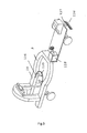
- Figure 4 illustrates the perspective view of the alternative integrated animal training device. According to the figure, as the steering wheel (119) is turned, the steering beam (145) connected to the steering wheel (119) from one end and connected to the valve (118) from other end, lock or unlock the channels in the valve (118) so that the hydraulic is directed in the desired direction. Preferably, the valve comprises four openings two of which are used to feed the hydraulic into the piston (116) ultimately providing direction change of the front wheels. The third opening is embodied for transmitting the hydraulic from hydraulic storage to the valve (118) by virtue of a feeding hydraulic line (143) and the fourth one is embodied for evacuating the excess hydraulic to the hydraulic storage by virtue of an evacuation hydraulic line (144).
- As seen in the Figure 4, the piston is fed with hydraulic from a right hydraulic line (141) and a left hydraulic line (142). Depending on the coming hydraulic, i.e. from right or left line, a piston arm (138) connected to the piston (116) is displaced in forward or backward directions. Since the piston arm (138) is rigidly attached to a directing beam (140), as the piston arm (138) is displaced accordingly the directing beam (140) is displaced in horizontal direction. For structural integrity, the directing beam (140) is supported by an outer housing (146), whereby the directing beam (140) is movable in the outer housing (146). Since the form of the directing beam (140) comprises a horizontal and a vertical component i.e. "T" like shape, horizontal displacement extent of the directing beam (140) is determined by the vertical component movable through displacement opening (147) formed in the outer housing (146).
- The directing beam (140) movable in the horizontal direction by actuation of the piston ( 116) is attached to a curved bar ( 149) by virtue of a middle connection (148). This curved bar (149) is preferably disposed in the lateral coverages (15). Once the piston (116) actuates the directing beam (140), the curved bar (149) is moved and transfers its motion to a straight bar (150). Accordingly, the straight bar (150) transfers the motion to a connecting rod (151) further connected to a vertical beam (152) from the other end. Consequently, a direction arm (115) connected from one end to the vertical beam (152) and connected from other end to the front wheel (113) transfers the motion to the front wheel (113).
- The above-mentioned components including piston (116), valve (118), directing beam (140), outer housing (146) etc. is covered by a protective lid (153) for preventing external effects thereof.
- Figure 5 illustrates the front and rear covering means in conjunction with the present invention. Once the animal is placed in the training device, the front and rear regions of the animal are closed by means of covering means (178). The mechanism driving these covering means (178) is seen in the figure. Preferably, two pivots (156,157) are fixed vertically to the convex structure legs (155) through upper bearings (160) and lower bearings (161). One of the pivots, actuator pivot (156), is a screwed pivot and actuated by a motor (168) preferably at the bottom side. The motor (168) is preferably an electric-based motor, however it may be driven by energy provided from the self-powered motor.
- An actuation ring (158) is annually placed to the actuator pivot (156). As the actuator pivot (156) is rotated, the actuation ring (158) screwed the inner surface is displaced in upwards and downwards directions. Alongside the actuator pivot (156), a support pivot (157) is placed so that the gravity force of the covering means (178) is met by the support pivot (157). Similarly, a support ring (159) connected rigidly to the actuator ring (158) is annually placed to the support pivot (157) and capable of displacing in upwards and downwards directions.
- An actuator ring arm (165) is fixed from one end to the actuator ring and pined from the other end to a wheel arm (164). The wheel arm is further pined from the other end to the center of a wheel (163) moving on a follower (162) comprising an eccentric pivot combination. A support ring arm (166) is pined from one end to the center of the wheel (163) and connected from other end to a holder arm (167) that is pined to fixed arm (179) connected to support ring (159).
- Once the actuator pivot (156) is rotated by the motor (168), the actuation ring (158) is displaced in vertical direction. In the mean time, the wheel (163) associated with the actuation ring (158) is moving on the follower (162) comprising eccentric pivot combination. As the wheel (163) is moving on the lower pivot of the eccentric pivot combination, the support ring arm (166) shifts its position and the covering means (178) connected to the support ring arm (166) shifts its position accordingly. Once the actuation ring (158) displaces to a certain point, the covering means (178) completely covers the front side of the animal.
- Similar covering movement applies to when the actuation ring (158) moves on the upper pivot of the eccentric pivot combination. Once the actuation ring (158) displaces to a certain point, the covering means (178) is completely lifted and the front side of the animal is opened.
- In the preferred embodiment of the invention, the above mentioned covering means (178) mechanism is assembled alongside the other leg of the convex structures so that the rear side of the animal are closed or opened.
- Air bags are provided to the covering means (178) so that the position of the animal can be controlled by a flexible embodiment. These air bags can be inflated as desired to confine the position of the animal.
- Figure 6 illustrates the mechanism providing displacing of the convex structures with respect to the lateral coverages in conjunction with the present invention. As seen from the figure, convex structure legs (155) are capable of moving in the lateral coverages (15) through the displacement opening (173). The convex structure legs (155) are connected to horizontal sledges (170) disposed in the lateral coverages (15).
- The horizontal sledges (170) are driven by a sledge motor (172) and a sledge spring (178) is provided between the sledge motor (172) and the horizontal sledge (170). As the sledges (170) are driven by the sledge motor (172), the convex structure legs (155) connected to the sledges (170) move accordingly.
- Figure 7 illustrates the magnetic-based structure disposed in the lateral coverages in conjunction with the present invention. Housings (174) in which electro-magnets (175) are disposed are formed preferably bilateral inner sides of the lateral coverages (15). A rod (177) capable of moving in the housing (174) and holding a ring (176) is embodied in the housing (174). This ring (176) is connected to the saddle (16) on the animal. Adjustable magnetic force provided by the electro-magnet renders the ring (176) to displace any desired amount in the housing (174).
Claims (21)
- An automatic animal training system comprising a horse training device driven by a tractor positioned front or rear region thereof and the lateral and rear sides (coverages) are covered by flexible material and at least one convex structure (7) surrounding the upper side of the training device and the legs thereof are positioned on the lateral sides of the training device characterized in that a valve (118) controlled by a steering wheel (119) positioned to the tractor at the rear region of the training device is provided and said valve (118) having preferably four openings for hydraulic flow through thereof, a piston (116) directed by hydraulic flow is provided and said piston (116) comprises a piston arm (138) connected to a directing beam (140), and curved bars (149) symmetrically connected to the directing beam (140), straight bars (150) connected from one end to the curved bar (149) and connected from the other end to connecting rods (151) are provided, and vertical beams (152) connected to the connecting rods (151) is provided and direction arms (115) connected from one end to the vertical beams (152) and from the other end to front wheels (113) are provided.
- An automatic animal training system according to claim 1, characterized in that a hydraulic feeding line (143) for the association of a hydraulic storage and the valve (118), a hydraulic evacuation line (144) for the association of a hydraulic storage and the valve (118), a right hydraulic line (141) and a left hydraulic line (142) for directing the hydraulic from the valve (118) to the piston (116) are provided.
- An automatic animal training system according to any one of the claims 1 to 2, characterized in that said directing beam (140) comprises a "T" like shape and the piston arm (138) is connected to vertical part of "T" like shaped directing beam (140).
- An automatic animal training system according to any one of the claims 1 to 3, characterized in that an outer housing (146) for supporting the directing beam (140) is provided and the vertical part of "T" like shaped directing beam (140) is displaceable in a displacement opening (147) of the outer housing (146).
- An automatic animal training system according to any one of the claims 1 to 4, characterized in that said directing beam (140) is disposed in the rear coverage and said curved bars (149) and straight bars (150) are disposed in the said lateral coverages.
- An automatic animal training system according to any one of the claims 1 to 5, characterized in that a protective lid (153) movable in upward and downward directions for covering said piston (116) and said directing beam (140) is provided.
- An automatic a nimal training system according to any one of the preceding claims, characterized in that at least one screwed actuator pivot (156) and at least one support pivot (157) are located alongside the convex structure legs (155) by virtue of upper bearings (160) and lower bearings (161).
- An automatic a nimal training system according to any one of the preceding claims, characterized in that an actuation ring (158) inner surface screwed thereof and movable through the axis of the actuator pivot (156), and a support ring (159) connected to the actuation ring and movable through the axis of the support pivot (157) are provided.
- An automatic a nimal training system according to any one of the preceding claims, characterized in that a motor (168) preferably positioned at the bottom side of the actuator pivot (156) for rotating thereof is provided.
- An automatic a nimal training system according to any one of the preceding claims, characterized in that a wheel (163) connected to the actuation ring (158) through an actuator ring arm (165) and a wheel arm (164) is provided.
- An automatic a nimal training system according to any one of the preceding claims, characterized in that a follower (162) comprising an eccentric pivot combination and the wheel (163) is movable thereon is provided.
- An automatic a nimal training system according to any one of the preceding claims, characterized in that a support ring arm (166) pined from one end to the wheel (163) center and connected from other end to a holder arm (167) pined to a fixed arm (179) connected to support ring (159) is provided.
- An automatic a nimal training system according to any one of the preceding claims, characterized in that covering means (178) connected to the holder arm (167) is provided.
- An automatic a nimal training system according to any one of the preceding claims, characterized in that mechanical components holding and actuating the covering means (178) are disposed both convex structure legs (155) for covering front and rear side of the animal in the training device.
- An automatic a nimal training system according to any one of the preceding claims, characterized in that air bags are provided in the covering means (178).
- An automatic a nimal training system according to any one of the preceding claims, characterized in that horizontal sledges (170) associated with the convex structure legs (155) are disposed in the lateral coverages (15).
- An automatic a nimal training system according to any one of the preceding claims, characterized in that a sledge spring (178) connected from one end to the horizontal sledge (170) and connected from other end to a sledge motor (172) is provided.
- An automatic a nimal training system according to any one of the preceding claims, characterized in that a displacement opening (173) is formed in the lateral coverages for displacing the convex structure legs (155) therein.
- An automatic a nimal training system according to any one of the preceding claims, characterized in that a housing (45) is provided bilateral sides of the lateral coverages (15) and a magnet (175), preferably an electro-magnet, is disposed therein.
- An automatic a nimal training system according to any one of the preceding claims, characterized in that a rod (177) movable in the housing (45) and a ring (176) connected to the rod (177) and connected to the saddle are provided.
- An automatic a nimal training system according to any one of the preceding claims, characterized in that said ring (176) is capable of moving through a magnetic force provided by the electro-magnet (175).
Priority Applications (1)
| Application Number | Priority Date | Filing Date | Title |
|---|---|---|---|
| SI200230498T SI1459624T1 (en) | 2001-04-17 | 2002-04-17 | Automatic system-based animal training device |
Applications Claiming Priority (9)
| Application Number | Priority Date | Filing Date | Title |
|---|---|---|---|
| TR200101003 | 2001-04-17 | ||
| TR200101003 | 2001-04-17 | ||
| TR2001/01994A TR200101994A2 (en) | 2001-07-11 | 2001-07-11 | Automatic animal training tool |
| TR200101994 | 2001-07-11 | ||
| TR200103372 | 2001-11-26 | ||
| TR2001/03372A TR200103372A2 (en) | 2001-11-26 | 2001-11-26 | Automatic animal training tool. |
| TR200200639 | 2002-03-11 | ||
| TR2002/00639A TR200200639A2 (en) | 2002-03-11 | 2002-03-11 | Automatic animal training tool. |
| EP02733773A EP1381271B1 (en) | 2001-04-17 | 2002-04-17 | Automatic system-based animal training device |
Related Parent Applications (2)
| Application Number | Title | Priority Date | Filing Date |
|---|---|---|---|
| EP02733773.2 Division | 2002-04-17 | ||
| EP02733773A Division EP1381271B1 (en) | 2001-04-17 | 2002-04-17 | Automatic system-based animal training device |
Publications (3)
| Publication Number | Publication Date |
|---|---|
| EP1459624A2 true EP1459624A2 (en) | 2004-09-22 |
| EP1459624A3 EP1459624A3 (en) | 2005-06-01 |
| EP1459624B1 EP1459624B1 (en) | 2006-12-13 |
Family
ID=27484942
Family Applications (2)
| Application Number | Title | Priority Date | Filing Date |
|---|---|---|---|
| EP04013684A Expired - Lifetime EP1459624B1 (en) | 2001-04-17 | 2002-04-17 | Automatic system-based animal training device |
| EP02733773A Expired - Lifetime EP1381271B1 (en) | 2001-04-17 | 2002-04-17 | Automatic system-based animal training device |
Family Applications After (1)
| Application Number | Title | Priority Date | Filing Date |
|---|---|---|---|
| EP02733773A Expired - Lifetime EP1381271B1 (en) | 2001-04-17 | 2002-04-17 | Automatic system-based animal training device |
Country Status (12)
| Country | Link |
|---|---|
| US (2) | US7089720B2 (en) |
| EP (2) | EP1459624B1 (en) |
| JP (1) | JP2004529641A (en) |
| CN (1) | CN100542400C (en) |
| AT (2) | ATE347800T1 (en) |
| AU (1) | AU2002305967B2 (en) |
| DE (2) | DE60209118T2 (en) |
| DK (2) | DK1459624T3 (en) |
| ES (2) | ES2280865T3 (en) |
| PT (2) | PT1459624E (en) |
| SI (2) | SI1381271T1 (en) |
| WO (1) | WO2002082892A2 (en) |
Cited By (1)
| Publication number | Priority date | Publication date | Assignee | Title |
|---|---|---|---|---|
| CN104085851A (en) * | 2014-07-16 | 2014-10-08 | 林宝江 | Lasso device |
Families Citing this family (21)
| Publication number | Priority date | Publication date | Assignee | Title |
|---|---|---|---|---|
| US7685970B1 (en) * | 2007-02-01 | 2010-03-30 | Rains Clayton D | Aerial capture-and-carry of cattle by land vehicle, and apparatus |
| US7770541B2 (en) * | 2008-03-28 | 2010-08-10 | Radio Systems Corporation | Animal training device responsive to an audible signal |
| US8151734B1 (en) * | 2009-05-15 | 2012-04-10 | S&S Enterprises, LLC | Training device and method of using |
| JP2013503641A (en) | 2009-09-02 | 2013-02-04 | ソマーク イノベイションズ, インコーポレイテッド | Animal marking devices, transfer assemblies and useful restraints |
| USD643162S1 (en) * | 2010-12-21 | 2011-08-09 | Larry Gardner | Rider simulation apparatus |
| USD670456S1 (en) | 2011-07-25 | 2012-11-06 | Larry Gardner | Rider simulation apparatus |
| US10117419B2 (en) | 2012-03-05 | 2018-11-06 | Ifetch, Llc | Pet exercise and entertainment device |
| USD797385S1 (en) | 2014-06-10 | 2017-09-12 | Ifetch, Llc | Fetching device for pets |
| US9345946B2 (en) | 2012-03-05 | 2016-05-24 | Ifetch, Llc | Pet exercise and entertainment device |
| US9700016B2 (en) | 2012-04-24 | 2017-07-11 | Somark Innovations, Inc. | Animal marking devices, transfer assemblies, and useful restraints |
| USD719706S1 (en) * | 2013-03-04 | 2014-12-16 | Ifetch, Llc | Dog exercising device |
| SG10201707223RA (en) | 2013-03-15 | 2017-10-30 | Somark Innovations Inc | Microelectronic animal identification |
| US9795819B2 (en) * | 2013-11-01 | 2017-10-24 | Michael A. Wehrell | Self-locomotion training systems and methods |
| WO2017136898A1 (en) | 2016-02-11 | 2017-08-17 | Somark Group Limited | A radio device for implantation in an animal, a method for making a radio device for implantation in an animal, a method for providing electrical power to a radio device attached to an animal, a method for implanting a radio device into an animal, an animal having implanted therein a radio device, and a radio device implanted in an animal |
| CN106718992B (en) * | 2017-01-07 | 2019-11-08 | 林勇翔 | A pigsty for promoting weight loss of pigs and enhancing the taste of pork |
| DE102017101879B4 (en) | 2017-01-31 | 2020-03-26 | Franz Gleinser | Guide system for riderless training of horses, camels and other animals |
| US11330798B2 (en) | 2017-10-12 | 2022-05-17 | Somark Group Limited | RFID tag insertion cartridge and an RFID tag insertion tool |
| CN112470988B (en) * | 2020-11-13 | 2022-02-15 | 武汉商学院 | A multifunctional monitoring bridle |
| CN112425544B (en) * | 2020-11-27 | 2022-07-15 | 东至县华仁家庭农场 | A feed delivery mechanism for aquaculture that can evenly expand the delivery range |
| IL285830A (en) | 2021-08-24 | 2022-07-01 | Early O M Ltd | Volatile organic compounds (voc’s) diagnosis system |
| GB2615542A (en) | 2022-02-09 | 2023-08-16 | Kurt Systems Uk Ltd | Equine fitness monitor system |
Citations (3)
| Publication number | Priority date | Publication date | Assignee | Title |
|---|---|---|---|---|
| US4266508A (en) | 1979-11-13 | 1981-05-12 | Mcnulty Robert A | Apparatus for simultaneously exercising a plurality of horses |
| US4619222A (en) | 1983-06-07 | 1986-10-28 | Hb Autonom | Animal training course, especially for race horses |
| WO2001097606A1 (en) | 2000-06-22 | 2001-12-27 | Mehmet Kurt | Automatic horse training system |
Family Cites Families (10)
| Publication number | Priority date | Publication date | Assignee | Title |
|---|---|---|---|---|
| US877504A (en) * | 1907-04-26 | 1908-01-28 | Loren Hoover | Apparatus for breaking or training animals. |
| US3099248A (en) * | 1962-01-25 | 1963-07-30 | Robert A Nash | Methods of training horses |
| US3349751A (en) * | 1966-02-14 | 1967-10-31 | Frostad George Carmon | Apparatus for exercising and training animals, particularly horses |
| FR2347955A1 (en) * | 1976-04-14 | 1977-11-10 | Bouvry Ets | RACING HORSE TRACK TRAINING INSTALLATION |
| US4130091A (en) * | 1976-12-23 | 1978-12-19 | Knudson M Theresa | Animal walker |
| US4708592A (en) * | 1985-04-15 | 1987-11-24 | Wind Production Company | Helicoidal structures, useful as wind turbines |
| FR2642325B1 (en) * | 1989-01-31 | 1991-05-17 | Ingenierie | DEVICE FOR MONITORING THE APPEARANCE IN PARTICULAR OF A HORSE AND MONITORING SYSTEM COMPRISING SAME |
| US5070816A (en) * | 1990-03-07 | 1991-12-10 | Wehrell Michael A | Sprint training exercise system and method |
| CA2077262C (en) * | 1992-08-31 | 1995-01-17 | Warren P. Halyung | Mobile capture and restraint device |
| DE19834257C2 (en) * | 1998-07-30 | 2002-08-08 | Frank Mauch | Method for monitoring an animal, in particular a horse |
-
2002
- 2002-04-17 AT AT04013684T patent/ATE347800T1/en active
- 2002-04-17 EP EP04013684A patent/EP1459624B1/en not_active Expired - Lifetime
- 2002-04-17 PT PT04013684T patent/PT1459624E/en unknown
- 2002-04-17 AT AT02733773T patent/ATE317219T1/en not_active IP Right Cessation
- 2002-04-17 ES ES04013684T patent/ES2280865T3/en not_active Expired - Lifetime
- 2002-04-17 DE DE60209118T patent/DE60209118T2/en not_active Expired - Fee Related
- 2002-04-17 CN CNB028083954A patent/CN100542400C/en not_active Expired - Fee Related
- 2002-04-17 SI SI200230309T patent/SI1381271T1/en unknown
- 2002-04-17 ES ES02733773T patent/ES2259083T3/en not_active Expired - Lifetime
- 2002-04-17 JP JP2002580712A patent/JP2004529641A/en active Pending
- 2002-04-17 US US10/475,046 patent/US7089720B2/en not_active Expired - Lifetime
- 2002-04-17 DK DK04013684T patent/DK1459624T3/en active
- 2002-04-17 PT PT02733773T patent/PT1381271E/en unknown
- 2002-04-17 AU AU2002305967A patent/AU2002305967B2/en not_active Expired
- 2002-04-17 EP EP02733773A patent/EP1381271B1/en not_active Expired - Lifetime
- 2002-04-17 DK DK02733773T patent/DK1381271T3/en active
- 2002-04-17 SI SI200230498T patent/SI1459624T1/en unknown
- 2002-04-17 DE DE602004003605T patent/DE602004003605T2/en not_active Expired - Lifetime
- 2002-04-17 WO PCT/TR2002/000016 patent/WO2002082892A2/en not_active Ceased
-
2006
- 2006-06-22 US US11/473,539 patent/US7287490B2/en not_active Expired - Lifetime
Patent Citations (3)
| Publication number | Priority date | Publication date | Assignee | Title |
|---|---|---|---|---|
| US4266508A (en) | 1979-11-13 | 1981-05-12 | Mcnulty Robert A | Apparatus for simultaneously exercising a plurality of horses |
| US4619222A (en) | 1983-06-07 | 1986-10-28 | Hb Autonom | Animal training course, especially for race horses |
| WO2001097606A1 (en) | 2000-06-22 | 2001-12-27 | Mehmet Kurt | Automatic horse training system |
Cited By (1)
| Publication number | Priority date | Publication date | Assignee | Title |
|---|---|---|---|---|
| CN104085851A (en) * | 2014-07-16 | 2014-10-08 | 林宝江 | Lasso device |
Also Published As
| Publication number | Publication date |
|---|---|
| DE60209118T2 (en) | 2006-10-05 |
| PT1459624E (en) | 2007-03-30 |
| WO2002082892A3 (en) | 2003-03-27 |
| EP1381271B1 (en) | 2006-02-08 |
| SI1381271T1 (en) | 2006-08-31 |
| DK1459624T3 (en) | 2007-04-16 |
| US7089720B2 (en) | 2006-08-15 |
| ES2259083T3 (en) | 2006-09-16 |
| CN1547430A (en) | 2004-11-17 |
| DE602004003605T2 (en) | 2007-09-27 |
| ES2280865T3 (en) | 2007-09-16 |
| DE602004003605D1 (en) | 2007-01-25 |
| EP1459624A3 (en) | 2005-06-01 |
| WO2002082892A2 (en) | 2002-10-24 |
| DK1381271T3 (en) | 2006-06-12 |
| PT1381271E (en) | 2006-06-30 |
| US20040244341A1 (en) | 2004-12-09 |
| US7287490B2 (en) | 2007-10-30 |
| US20060236661A1 (en) | 2006-10-26 |
| ATE347800T1 (en) | 2007-01-15 |
| EP1459624B1 (en) | 2006-12-13 |
| AU2002305967B2 (en) | 2008-12-11 |
| ATE317219T1 (en) | 2006-02-15 |
| DE60209118D1 (en) | 2006-04-20 |
| CN100542400C (en) | 2009-09-23 |
| SI1459624T1 (en) | 2007-06-30 |
| JP2004529641A (en) | 2004-09-30 |
| EP1381271A2 (en) | 2004-01-21 |
Similar Documents
| Publication | Publication Date | Title |
|---|---|---|
| EP1459624B1 (en) | Automatic system-based animal training device | |
| DE69319155T3 (en) | Device for automatic milking of animals | |
| US4451045A (en) | Steer or calf legs practice roping device | |
| AU2002305967A1 (en) | Automatic system-based animal training device | |
| US20060170163A1 (en) | Roping training device speed roper | |
| US4602687A (en) | Drive mechanism for turf aerating apparatus | |
| EP3914061B1 (en) | A method for ploughing farmland and an autonomous tractor for employing the method | |
| CA1267561A (en) | Turf aerating apparatus | |
| TNSN95073A1 (en) | FUNGICIDE COMPOSITION AND METHOD FOR CONTROLLING FUNGI INFESTATION | |
| KR100729829B1 (en) | Assembling machine | |
| US3783953A (en) | Post driving apparatus | |
| US4362127A (en) | Milking barn system and apparatus | |
| DE69333988T2 (en) | Device for milking animals | |
| US20080011494A1 (en) | Grooming Apparatus for Artificial Racetrack Surface | |
| JP4934518B2 (en) | Traveling seedling transplanter | |
| WO1999028008A1 (en) | Steerable animal statue for a carriage | |
| US20110111379A1 (en) | Livestock training aid | |
| DE69527859T2 (en) | Method of milking animals | |
| JPS6415Y2 (en) | ||
| KR20200077502A (en) | Eating season | |
| JPH0649178Y2 (en) | Film strut driving device | |
| JP2000253712A (en) | Working device lifting mechanism of paddy field machine | |
| CN115176779A (en) | Tea tree pest control device and control method thereof | |
| DE19737300A1 (en) | Mechanical horse for use as horse riding trainer | |
| EP0913080A3 (en) | Vehicle for supporting operating devices for pruning and/or other treatments of plants |
Legal Events
| Date | Code | Title | Description |
|---|---|---|---|
| PUAI | Public reference made under article 153(3) epc to a published international application that has entered the european phase |
Free format text: ORIGINAL CODE: 0009012 |
|
| 17P | Request for examination filed |
Effective date: 20040609 |
|
| AC | Divisional application: reference to earlier application |
Ref document number: 1381271 Country of ref document: EP Kind code of ref document: P |
|
| AK | Designated contracting states |
Kind code of ref document: A2 Designated state(s): AT BE CH CY DE DK ES FI FR GB GR IE IT LI LU MC NL PT SE TR |
|
| AX | Request for extension of the european patent |
Extension state: AL LT LV MK SI |
|
| D17P | Request for examination filed (deleted) | ||
| PUAL | Search report despatched |
Free format text: ORIGINAL CODE: 0009013 |
|
| AK | Designated contracting states |
Kind code of ref document: A3 Designated state(s): AT BE CH CY DE DK ES FI FR GB GR IE IT LI LU MC NL PT SE TR |
|
| AX | Request for extension of the european patent |
Extension state: AL LT LV MK RO SI |
|
| R17P | Request for examination filed (corrected) |
Effective date: 20050429 |
|
| AKX | Designation fees paid |
Designated state(s): AT BE CH CY DE DK ES FI FR GB GR IE IT LI LU MC NL PT SE TR |
|
| AXX | Extension fees paid |
Extension state: MK Payment date: 20040608 Extension state: AL Payment date: 20040608 Extension state: RO Payment date: 20041108 Extension state: SI Payment date: 20040608 Extension state: LT Payment date: 20040608 Extension state: LV Payment date: 20040608 |
|
| GRAP | Despatch of communication of intention to grant a patent |
Free format text: ORIGINAL CODE: EPIDOSNIGR1 |
|
| GRAS | Grant fee paid |
Free format text: ORIGINAL CODE: EPIDOSNIGR3 |
|
| GRAA | (expected) grant |
Free format text: ORIGINAL CODE: 0009210 |
|
| AC | Divisional application: reference to earlier application |
Ref document number: 1381271 Country of ref document: EP Kind code of ref document: P |
|
| AK | Designated contracting states |
Kind code of ref document: B1 Designated state(s): AT BE CH CY DE DK ES FI FR GB GR IE IT LI LU MC NL PT SE TR |
|
| AX | Request for extension of the european patent |
Extension state: AL LT LV MK RO SI |
|
| REG | Reference to a national code |
Ref country code: GB Ref legal event code: FG4D |
|
| REG | Reference to a national code |
Ref country code: CH Ref legal event code: EP |
|
| REG | Reference to a national code |
Ref country code: IE Ref legal event code: FG4D |
|
| REF | Corresponds to: |
Ref document number: 602004003605 Country of ref document: DE Date of ref document: 20070125 Kind code of ref document: P |
|
| REG | Reference to a national code |
Ref country code: PT Ref legal event code: SC4A Free format text: AVAILABILITY OF NATIONAL TRANSLATION Effective date: 20070313 |
|
| REG | Reference to a national code |
Ref country code: SE Ref legal event code: TRGR |
|
| REG | Reference to a national code |
Ref country code: DK Ref legal event code: T3 |
|
| REG | Reference to a national code |
Ref country code: GR Ref legal event code: EP Ref document number: 20070400840 Country of ref document: GR |
|
| REG | Reference to a national code |
Ref country code: CH Ref legal event code: NV Representative=s name: MICHELI & CIE SA |
|
| ET | Fr: translation filed | ||
| REG | Reference to a national code |
Ref country code: ES Ref legal event code: FG2A Ref document number: 2280865 Country of ref document: ES Kind code of ref document: T3 |
|
| PLBE | No opposition filed within time limit |
Free format text: ORIGINAL CODE: 0009261 |
|
| STAA | Information on the status of an ep patent application or granted ep patent |
Free format text: STATUS: NO OPPOSITION FILED WITHIN TIME LIMIT |
|
| 26N | No opposition filed |
Effective date: 20070914 |
|
| PG25 | Lapsed in a contracting state [announced via postgrant information from national office to epo] |
Ref country code: LU Free format text: LAPSE BECAUSE OF NON-PAYMENT OF DUE FEES Effective date: 20070417 Ref country code: CY Free format text: LAPSE BECAUSE OF FAILURE TO SUBMIT A TRANSLATION OF THE DESCRIPTION OR TO PAY THE FEE WITHIN THE PRESCRIBED TIME-LIMIT Effective date: 20061213 |
|
| PGFP | Annual fee paid to national office [announced via postgrant information from national office to epo] |
Ref country code: DK Payment date: 20110817 Year of fee payment: 10 Ref country code: MC Payment date: 20110816 Year of fee payment: 10 Ref country code: CH Payment date: 20110915 Year of fee payment: 10 |
|
| PGFP | Annual fee paid to national office [announced via postgrant information from national office to epo] |
Ref country code: PT Payment date: 20110816 Year of fee payment: 10 Ref country code: ES Payment date: 20110829 Year of fee payment: 10 Ref country code: FI Payment date: 20110822 Year of fee payment: 10 Ref country code: FR Payment date: 20110908 Year of fee payment: 10 Ref country code: GR Payment date: 20110823 Year of fee payment: 10 Ref country code: AT Payment date: 20110819 Year of fee payment: 10 Ref country code: SE Payment date: 20110829 Year of fee payment: 10 |
|
| PGFP | Annual fee paid to national office [announced via postgrant information from national office to epo] |
Ref country code: NL Payment date: 20110822 Year of fee payment: 10 Ref country code: IT Payment date: 20110822 Year of fee payment: 10 |
|
| PGFP | Annual fee paid to national office [announced via postgrant information from national office to epo] |
Ref country code: BE Payment date: 20110923 Year of fee payment: 10 |
|
| REG | Reference to a national code |
Ref country code: PT Ref legal event code: MM4A Free format text: LAPSE DUE TO NON-PAYMENT OF FEES Effective date: 20121017 |
|
| BERE | Be: lapsed |
Owner name: KURT, MEHMET Effective date: 20120430 |
|
| REG | Reference to a national code |
Ref country code: NL Ref legal event code: V1 Effective date: 20121101 |
|
| REG | Reference to a national code |
Ref country code: DK Ref legal event code: EBP |
|
| REG | Reference to a national code |
Ref country code: LT Ref legal event code: MM9D Effective date: 20120417 |
|
| PG25 | Lapsed in a contracting state [announced via postgrant information from national office to epo] |
Ref country code: MC Free format text: LAPSE BECAUSE OF NON-PAYMENT OF DUE FEES Effective date: 20120430 |
|
| REG | Reference to a national code |
Ref country code: CH Ref legal event code: PL |
|
| REG | Reference to a national code |
Ref country code: SE Ref legal event code: EUG |
|
| REG | Reference to a national code |
Ref country code: AT Ref legal event code: MM01 Ref document number: 347800 Country of ref document: AT Kind code of ref document: T Effective date: 20120417 |
|
| GBPC | Gb: european patent ceased through non-payment of renewal fee |
Effective date: 20120417 |
|
| REG | Reference to a national code |
Ref country code: SI Ref legal event code: KO00 Effective date: 20121123 |
|
| REG | Reference to a national code |
Ref country code: IE Ref legal event code: MM4A |
|
| REG | Reference to a national code |
Ref country code: FR Ref legal event code: ST Effective date: 20121228 |
|
| REG | Reference to a national code |
Ref country code: GR Ref legal event code: ML Ref document number: 20070400840 Country of ref document: GR Effective date: 20121102 |
|
| PG25 | Lapsed in a contracting state [announced via postgrant information from national office to epo] |
Ref country code: CH Free format text: LAPSE BECAUSE OF NON-PAYMENT OF DUE FEES Effective date: 20120430 Ref country code: FI Free format text: LAPSE BECAUSE OF NON-PAYMENT OF DUE FEES Effective date: 20120417 Ref country code: AT Free format text: LAPSE BECAUSE OF NON-PAYMENT OF DUE FEES Effective date: 20120417 Ref country code: IE Free format text: LAPSE BECAUSE OF NON-PAYMENT OF DUE FEES Effective date: 20120417 Ref country code: BE Free format text: LAPSE BECAUSE OF NON-PAYMENT OF DUE FEES Effective date: 20120430 Ref country code: LI Free format text: LAPSE BECAUSE OF NON-PAYMENT OF DUE FEES Effective date: 20120430 |
|
| PG25 | Lapsed in a contracting state [announced via postgrant information from national office to epo] |
Ref country code: IT Free format text: LAPSE BECAUSE OF NON-PAYMENT OF DUE FEES Effective date: 20120417 Ref country code: FR Free format text: LAPSE BECAUSE OF NON-PAYMENT OF DUE FEES Effective date: 20120430 Ref country code: SE Free format text: LAPSE BECAUSE OF NON-PAYMENT OF DUE FEES Effective date: 20120418 Ref country code: GR Free format text: LAPSE BECAUSE OF NON-PAYMENT OF DUE FEES Effective date: 20121102 Ref country code: PT Free format text: LAPSE BECAUSE OF NON-PAYMENT OF DUE FEES Effective date: 20121017 |
|
| PG25 | Lapsed in a contracting state [announced via postgrant information from national office to epo] |
Ref country code: NL Free format text: LAPSE BECAUSE OF NON-PAYMENT OF DUE FEES Effective date: 20121101 |
|
| REG | Reference to a national code |
Ref country code: GB Ref legal event code: S28 Free format text: APPLICATION FILED |
|
| REG | Reference to a national code |
Ref country code: GB Ref legal event code: S28 Free format text: RESTORATION ALLOWED Effective date: 20130612 |
|
| REG | Reference to a national code |
Ref country code: ES Ref legal event code: FD2A Effective date: 20130716 |
|
| PG25 | Lapsed in a contracting state [announced via postgrant information from national office to epo] |
Ref country code: ES Free format text: LAPSE BECAUSE OF NON-PAYMENT OF DUE FEES Effective date: 20120418 |
|
| REG | Reference to a national code |
Ref country code: FR Ref legal event code: RN Effective date: 20130723 |
|
| REG | Reference to a national code |
Ref country code: IE Ref legal event code: NE4A |
|
| PG25 | Lapsed in a contracting state [announced via postgrant information from national office to epo] |
Ref country code: DK Free format text: LAPSE BECAUSE OF NON-PAYMENT OF DUE FEES Effective date: 20120430 |
|
| REG | Reference to a national code |
Ref country code: FR Ref legal event code: IC Effective date: 20131220 |
|
| PGRI | Patent reinstated in contracting state [announced from national office to epo] |
Ref country code: IE Effective date: 20140131 |
|
| PGFP | Annual fee paid to national office [announced via postgrant information from national office to epo] |
Ref country code: DE Payment date: 20140430 Year of fee payment: 13 |
|
| REG | Reference to a national code |
Ref country code: DE Ref legal event code: R119 Ref document number: 602004003605 Country of ref document: DE |
|
| PG25 | Lapsed in a contracting state [announced via postgrant information from national office to epo] |
Ref country code: DE Free format text: LAPSE BECAUSE OF NON-PAYMENT OF DUE FEES Effective date: 20151103 |
|
| PG25 | Lapsed in a contracting state [announced via postgrant information from national office to epo] |
Ref country code: GB Free format text: THE PATENT HAS BEEN ANNULLED BY A DECISION OF A NATIONAL AUTHORITY Effective date: 20120417 |
|
| PGFP | Annual fee paid to national office [announced via postgrant information from national office to epo] |
Ref country code: TR Payment date: 20190411 Year of fee payment: 18 |
|
| PGFP | Annual fee paid to national office [announced via postgrant information from national office to epo] |
Ref country code: GB Payment date: 20210427 Year of fee payment: 20 Ref country code: IE Payment date: 20210423 Year of fee payment: 20 |
|
| REG | Reference to a national code |
Ref country code: GB Ref legal event code: PE20 Expiry date: 20220416 |
|
| REG | Reference to a national code |
Ref country code: IE Ref legal event code: MK9A |
|
| PG25 | Lapsed in a contracting state [announced via postgrant information from national office to epo] |
Ref country code: TR Free format text: LAPSE BECAUSE OF NON-PAYMENT OF DUE FEES Effective date: 20200417 |
|
| PG25 | Lapsed in a contracting state [announced via postgrant information from national office to epo] |
Ref country code: IE Free format text: LAPSE BECAUSE OF EXPIRATION OF PROTECTION Effective date: 20220417 Ref country code: GB Free format text: LAPSE BECAUSE OF EXPIRATION OF PROTECTION Effective date: 20220416 |