EP1458614B1 - Multiple cavity valve plate with floating shoe for container labeling apparatus - Google Patents
Multiple cavity valve plate with floating shoe for container labeling apparatus Download PDFInfo
- Publication number
- EP1458614B1 EP1458614B1 EP02739661A EP02739661A EP1458614B1 EP 1458614 B1 EP1458614 B1 EP 1458614B1 EP 02739661 A EP02739661 A EP 02739661A EP 02739661 A EP02739661 A EP 02739661A EP 1458614 B1 EP1458614 B1 EP 1458614B1
- Authority
- EP
- European Patent Office
- Prior art keywords
- vacuum
- cavity
- valve body
- floating shoe
- label
- Prior art date
- Legal status (The legal status is an assumption and is not a legal conclusion. Google has not performed a legal analysis and makes no representation as to the accuracy of the status listed.)
- Expired - Lifetime
Links
Images



Classifications
-
- B—PERFORMING OPERATIONS; TRANSPORTING
- B65—CONVEYING; PACKING; STORING; HANDLING THIN OR FILAMENTARY MATERIAL
- B65C—LABELLING OR TAGGING MACHINES, APPARATUS, OR PROCESSES
- B65C9/00—Details of labelling machines or apparatus
- B65C9/08—Label feeding
- B65C9/18—Label feeding from strips, e.g. from rolls
- B65C9/1803—Label feeding from strips, e.g. from rolls the labels being cut from a strip
- B65C9/1815—Label feeding from strips, e.g. from rolls the labels being cut from a strip and transferred by suction means
- B65C9/1819—Label feeding from strips, e.g. from rolls the labels being cut from a strip and transferred by suction means the suction means being a vacuum drum
-
- Y—GENERAL TAGGING OF NEW TECHNOLOGICAL DEVELOPMENTS; GENERAL TAGGING OF CROSS-SECTIONAL TECHNOLOGIES SPANNING OVER SEVERAL SECTIONS OF THE IPC; TECHNICAL SUBJECTS COVERED BY FORMER USPC CROSS-REFERENCE ART COLLECTIONS [XRACs] AND DIGESTS
- Y10—TECHNICAL SUBJECTS COVERED BY FORMER USPC
- Y10S—TECHNICAL SUBJECTS COVERED BY FORMER USPC CROSS-REFERENCE ART COLLECTIONS [XRACs] AND DIGESTS
- Y10S137/00—Fluid handling
- Y10S137/907—Vacuum-actuated valves
-
- Y—GENERAL TAGGING OF NEW TECHNOLOGICAL DEVELOPMENTS; GENERAL TAGGING OF CROSS-SECTIONAL TECHNOLOGIES SPANNING OVER SEVERAL SECTIONS OF THE IPC; TECHNICAL SUBJECTS COVERED BY FORMER USPC CROSS-REFERENCE ART COLLECTIONS [XRACs] AND DIGESTS
- Y10—TECHNICAL SUBJECTS COVERED BY FORMER USPC
- Y10T—TECHNICAL SUBJECTS COVERED BY FORMER US CLASSIFICATION
- Y10T137/00—Fluid handling
- Y10T137/8593—Systems
- Y10T137/87249—Multiple inlet with multiple outlet
-
- Y—GENERAL TAGGING OF NEW TECHNOLOGICAL DEVELOPMENTS; GENERAL TAGGING OF CROSS-SECTIONAL TECHNOLOGIES SPANNING OVER SEVERAL SECTIONS OF THE IPC; TECHNICAL SUBJECTS COVERED BY FORMER USPC CROSS-REFERENCE ART COLLECTIONS [XRACs] AND DIGESTS
- Y10—TECHNICAL SUBJECTS COVERED BY FORMER USPC
- Y10T—TECHNICAL SUBJECTS COVERED BY FORMER US CLASSIFICATION
- Y10T156/00—Adhesive bonding and miscellaneous chemical manufacture
- Y10T156/10—Methods of surface bonding and/or assembly therefor
- Y10T156/1002—Methods of surface bonding and/or assembly therefor with permanent bending or reshaping or surface deformation of self sustaining lamina
- Y10T156/1028—Methods of surface bonding and/or assembly therefor with permanent bending or reshaping or surface deformation of self sustaining lamina by bending, drawing or stretch forming sheet to assume shape of configured lamina while in contact therewith
- Y10T156/1033—Flexible sheet to cylinder lamina
Definitions
- the present invention pertains generally to the field of labeling containers wherein a stationary vacuum plate assembly provides different levels of vacuum to a rotating vacuum drum used to support segments of label material.
- Labeling containers by applying preprinted film labels is a popular alternative to conventional lithography.
- Plastic containers, metal cans and glass bottles can be labeled effectively with film labels.
- Labeling speed is an important consideration in high production canning and bottling plants, since it is unacceptable for labeling processes to impede productivity of a bottling or canning line. Labeling speed is of paramount importance with labeling speeds in excess of ten containers per second being possible to achieve with some labeling materials. Generally, thicker materials that are resistant to stretching are easier to handle by conventional labeling machines.
- Some labeling materials include coatings or treatments that result in higher coefficients of friction that can interfere with the labeling process. Labels having a higher coefficient of friction tend to become over tensioned more easily which aggravates problems associated with over tensioning.
- Another problem encountered when labels are supported by a vacuum drum during the labeling process is that glue applicators for applying glue to the label segments can become jammed by labels if insufficient vacuum is provided to prevent the labels from following the glue applicator.
- the present invention satisfies that need, as well as others, and overcomes deficiencies found in current label handling techniques.
- the present invention is defined by claim 1 and pertains to a multiple port valve plate assembly for use with a rotating vacuum drum in a label apparatus of the type described in U.S. Patent No. 5,486,253.
- the apparatus generally comprises a disk-shaped valve body, having first and second arcuate-shaped stationary vacuum cavities, and a floating shoe positioned in a receptacle in the valve body intermediate to the position of the first and second stationary vacuum cavities.
- the floating shoe which moves within the receptacle, has a third arcuate-shaped vacuum cavity that also moves, or "floats,” in the valve body with the floating shoe.
- a spring material such as sponge rubber, is positioned between the floating shoe and the inner wall of the receptacle so as to hold the floating shoe against the wear plate in system.
- One of the stationary vacuum cavities is divided into two spaced-apart, arcuate-shaped segments that are interconnected by a channel in the valve body, and a vacuum control valve is provided for controlling the amount of vacuum supplied by the interconnecting channel to one of the segments.
- a pressure port for blow-off is also provided in the valve body.
- Each of the stationary vacuum cavities and the floating shoe include a vacuum fittings configured for coupling the cavities to separate sources of vacuum.
- the first stationary vacuum cavity is configured to be supplied with a level of vacuum suitable for the vacuum drum picking up a label segment from a cutter with limited tension.
- the intermediate floating cavity is configured to be supplied with another, higher level of vacuum suitable for the vacuum drum firmly griping the cut label segment as an adhesive is applied to the label segment.
- the second stationary vacuum cavity is configured to be supplied with a lower level of vacuum suitable for the vacuum drum holding the label while the label is being transferred to a container.
- the pressure port is configured to be provided with a high pressure for facilitating release of the label from the vacuum drum as it contacts the container.
- the present invention improves the seal between the fixed valve plate and the rotating vacuum drum at the point of high vacuum so that vacuum loss is reduced.
- This reduced vacuum loss has the advantage of allowing a smaller vacuum source to be used to maintain the high vacuum level, thus reducing the cost of the vacuum pump or generator, and by reducing the operation cost to produce the vacuum. It also provides a more precise control of the vacuum at the point of adhesive application and eliminates the spread of high vacuum to adjacent ports that can negatively affect the label cutting and application by changing the vacuum level in these adjacent ports and chambers on a random basis.
- the vacuum seal can be affected by warping and/or wear of the plate caused by heat and general use.
- the floating shoe reduces the effect of warping or wear by reducing the contact surface area at the critical high vacuum point.
- An object of the invention is to provide a vacuum plate assembly with a plurality of cavities for providing different levels of vacuum to a vacuum drum in a container labeling apparatus, wherein thin films can be swiftly and accurately applied with minimum scrap or wastage.
- Another object of the invention is to provide a vacuum plate assembly with a plurality of cavities for providing different levels of vacuum to a vacuum drum in a container labeling apparatus, wherein ultra-thin stretchable film can be applied without reducing labeling speeds or over tensioning label material during the labeling process.
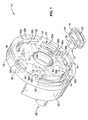
- FIG. 1 a bottom perspective view of a multiple port vacuum plate assembly according to the present invention with the floating shoe shown exploded from the assembly.
- FIG. 2 is a bottom plan view of the valve body portion of the assembly shown in FIG. 1 showing the internal cavities and interconnections.
- FIG. 3 is a cross-sectional view of the valve body shown in FIG. 2 taken through line 3-3.
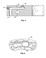
- FIG. 4 is a cross-sectional view of valve body shown in FIG. 2 taken through line 4-4.
- FIG. 5 is a bottom plan view of the floating shoe shown in FIG. 1.
- FIG. 6 is a top plan schematic view of the assembly shown in FIG. 1 connected to vacuum and pressure supplies.
- FIG. 1 through FIG. 6 the apparatus generally shown in FIG. 1 through FIG. 6. It will be appreciated that the apparatus may vary as to configuration and as to details of the parts, and that the method may vary as to the specific steps and sequence, without departing from the basic concepts as disclosed herein.
- FIG. 1 a multiple cavity vacuum valve plate assembly 10 according to the present invention is shown.
- the assembly shown is used as a component of a vacuum drum in a labeling apparatus and method as described in U.S. Patent No. 5,486,253. Accordingly, the details of the vacuum drum and operation of the labeling apparatus and method will not be repeated herein.
- valve plate assembly 10 includes a disk-shaped valve body 12 with a stationary arcuate-shaped low vacuum cavity 14, an arcuate-shaped receptacle 16 for receiving a floating shoe 18, a stationary low vacuum cavity 20 having arcuate-shaped first and second segments 22a, 22b, a stationary circular-shaped high pressure blow-off port 24, and a stationary arcuate-shaped high pressure blow-off port 26.
- Vacuum cavity 14 is configured to receive a vacuum supply through an inlet port 28 in a vacuum fitting 30 which is mounted to the upper surface of valve body 12 with standard fasteners, such as screws, extending from the vacuum fitting into receptacles 32a through 32d.
- Vacuum cavity 20 is configured to be connected to a low vacuum supply through an inlet port 34 in a vacuum fitting 36, which is mounted to the upper surface of valve body 12 with standard fasteners extending from the vacuum fitting into receptacles 38a through 38d. It will be appreciated that the vacuum level in these arcuate vacuum cavities will decrease with the distance away from the inlet ports.
- Blow-off port 24 is configured to be connected to a high a pressure supply through an inlet pressure port 52 (FIG. 2).
- Blow-off port 26 is configured to be connected to a high pressure supply through an inlet pressure port 40.
- cavity 14 opens into an inlet port 42 in the upper surface of valve body 12 that mates with a corresponding port in vacuum fitting 30 and connects to inlet port 28.
- cavity segment 22a opens into an inlet port 44 in the upper surface of valve body 12 that mates with a corresponding port (not shown) in vacuum fitting 36.
- cavities 22a, 22b are interconnected internally to valve body 12 by means of a cross-connecting channel 46 that is cross-drilled in valve body 12. It will be appreciated that the vacuum level to cavity 22b will be lower than that in cavity 22a due to the distance from inlet port 34.
- a control port 48 through the upper surface of valve body 12 is provided in channel 46 that can be used with a plug, screw valve or the like to adjust the vacuum level to cavity 22b.
- a plug 50 is provided to seal off the end of channel 46 in the sidewall of valve body 12 where the channel was drilled.
- blow-off port 24 is connected to inlet port 52 in the upper surface of valve body 12 though a channel 54 that is cross-drilled in valve body 12.
- a plug 56 is provided to seal off the end of channel 54 in the sidewall of valve body 12 where the channel was drilled.
- floating shoe 18 fits within receptacle 16 in valve body 12.
- Receptacle 16 opens into a hole 58 through which a vacuum fitting 60 attached to floating shoe 18 extends.
- vacuum fitting 60 opens into an arcuate cavity 62 within floating shoe 18.
- cavity 62 is not stationary within valve body 12 as is the case with the other cavities. Instead, cavity 62 moves or "floats" within receptacle 16.
- a spring material 64 such as foam rubber or sponge, is attached to floating shoe 18 and positioned between floating shoe 18 and inner wall 66 of receptacle 16 to hold floating shoe 18 against the wear plate in the system.
- one or more separate or nested coil springs could be used.
- Vacuum fitting 60 is screwed into a threaded hole 68 in floating shoe 18 or otherwise attached to floating shoe 18 in such a way as to create flow communication between port 70 in vacuum fitting 60 and cavity 62.
- Port 70 is configured to be connected to a high vacuum supply.
- valve plate assembly 10 remains fixed in a stationary position while a rotating vacuum drum rotates around the circumference of valve plate assembly 10.
- cavity 14 is a low vacuum cavity to facilitate transfer of cut label segments from the cutter to the vacuum drum
- floating shoe 18 provides a higher vacuum level to facilitate retention of cut label segments on the vacuum drum
- cavity 20 is a lower vacuum cavity to facilitate transfer of label segments from the vacuum drum to the container (e.g., label roll-on)
- blow-off ports 24 and 26 are high pressure ports for blow off to further facilitate transfer of label segments from the vacuum drum to the container being labeled. Note that it is important that a low vacuum level be provided to cavity 14 to minimize tension on the label as it is being transferred from the cutter to the vacuum drum.
- Splitting or misalignment of the label can occur if excessive tension is exerted by the vacuum drum on the label segment as it pulls the leading edge of the label segment off of the cutter drum and onto and around the vacuum drum.
- the high vacuum provided by floating shoe 18 retains the label segment in place as it moves into position for glue application.
- the high level of vacuum retention prevents slippage and misalignment of the label segment as the vacuum drum rotates the label into position for glue application.
- the high level of vacuum also prevents the label segment from following the glue roller that can lead to the label segment becoming caught in the glue application.
- Blow-off port 24 aids in separating the label from the vacuum drum as it is applied to the container. Note that blow-off port 24 is positioned to release the label segments at a point where the vacuum drum will initially contact the containers being labeled.
- the lower vacuum cavity segment 22b after blow-off port 24 is provided for holding the label in place during transfer to the container to prevent misalignment thereon and to prevent mismatch of the leading and trailing edges.
- Blow-off port 26 aids in the final separation and transfer of the label to the container.
- a vacuum source or multiple vacuum sources provide the same or different low vacuum levels to cavities 14 and 20 through first 28 and second 34 low pressure vacuum inlets in vacuum 30, 36, respectively.
- a separate vacuum source provides the high vacuum level to cavity 62 in floating shoe 18 through inlet port 70.
- a high pressure source provides the blow-off pressure supply to blow-off port 24 through inlet port 52.
- the same or a separate high pressure source provides the blow-off pressure supply to blow-off port 26 through inlet port 40.
- this invention provides multiple vacuum and pressure supplies to facilitate cut label segments being picked up by a vacuum drum, holding the label segments on the vacuum drum while adhesive is applied to the label segments, and applying the label segments to containers.
- the floating shoe changes position based on the presence or absence of vacuum, and functions as a continuously variable valve to equalize vacuum variations due to, for example, changes in rotational speed of the valve body or changes in label porosity.
- the present invention finds industrial applicability in the field of labeling equipment used to label plastic containers, metal cans and glass bottles with film labels.
- the present invention satisfies the need for a method of selectively controlling the amount of vacuum supplied to a vacuum drum during various stages of the labeling process and overcomes deficiencies found in current labeling techniques.
Landscapes
- Labeling Devices (AREA)
- Check Valves (AREA)
- Valve Housings (AREA)
- Details Of Valves (AREA)
Description
- The present invention pertains generally to the field of labeling containers wherein a stationary vacuum plate assembly provides different levels of vacuum to a rotating vacuum drum used to support segments of label material.
- Labeling containers by applying preprinted film labels is a popular alternative to conventional lithography. Various environmental problems, including air pollution and recycling concerns, strongly favor adoption of preprinted films for labeling containers. Plastic containers, metal cans and glass bottles can be labeled effectively with film labels.
- Cost considerations have led to the development of thin films which have the advantage of reducing the cost of materials used but require increasingly more stringent process controls to allow high-speed labeling equipment to handle thin, stretchable, and relatively flimsy labeling materials.
- Labeling speed is an important consideration in high production canning and bottling plants, since it is unacceptable for labeling processes to impede productivity of a bottling or canning line. Labeling speed is of paramount importance with labeling speeds in excess of ten containers per second being possible to achieve with some labeling materials. Generally, thicker materials that are resistant to stretching are easier to handle by conventional labeling machines.
- When thin labeling materials are run at high speeds, problems, such as label splitting, stretching labels and misalignment of labels, are encountered. With roll-fed labels, when the labels are cut from the web of label material, excessive tension on the label can cause the labels to split instead of being cut. Similarly, over tensioning thin labels can cause the labels to stretch as they are applied to the vacuum drum. As the labels are transferred to a vacuum drum, excessive vacuum can cause the label segment to shift or snap leading to misaligned labels on the containers.
- Some labeling materials include coatings or treatments that result in higher coefficients of friction that can interfere with the labeling process. Labels having a higher coefficient of friction tend to become over tensioned more easily which aggravates problems associated with over tensioning.
- Another problem encountered when labels are supported by a vacuum drum during the labeling process is that glue applicators for applying glue to the label segments can become jammed by labels if insufficient vacuum is provided to prevent the labels from following the glue applicator.
- Therefore, there is a need for a method of selectively controlling the amount of vacuum supplied to a vacuum drum during different stages of the labeling process. The present invention satisfies that need, as well as others, and overcomes deficiencies found in current label handling techniques.
- The present invention is defined by claim 1 and pertains to a multiple port valve plate assembly for use with a rotating vacuum drum in a label apparatus of the type described in U.S. Patent No. 5,486,253. By way of example, and not of limitation, the apparatus generally comprises a disk-shaped valve body, having first and second arcuate-shaped stationary vacuum cavities, and a floating shoe positioned in a receptacle in the valve body intermediate to the position of the first and second stationary vacuum cavities. The floating shoe, which moves within the receptacle, has a third arcuate-shaped vacuum cavity that also moves, or "floats," in the valve body with the floating shoe. A spring material, such as sponge rubber, is positioned between the floating shoe and the inner wall of the receptacle so as to hold the floating shoe against the wear plate in system. One of the stationary vacuum cavities is divided into two spaced-apart, arcuate-shaped segments that are interconnected by a channel in the valve body, and a vacuum control valve is provided for controlling the amount of vacuum supplied by the interconnecting channel to one of the segments. In addition, a pressure port for blow-off is also provided in the valve body. Each of the stationary vacuum cavities and the floating shoe include a vacuum fittings configured for coupling the cavities to separate sources of vacuum.
- The first stationary vacuum cavity is configured to be supplied with a level of vacuum suitable for the vacuum drum picking up a label segment from a cutter with limited tension. The intermediate floating cavity is configured to be supplied with another, higher level of vacuum suitable for the vacuum drum firmly griping the cut label segment as an adhesive is applied to the label segment. The second stationary vacuum cavity is configured to be supplied with a lower level of vacuum suitable for the vacuum drum holding the label while the label is being transferred to a container. The pressure port is configured to be provided with a high pressure for facilitating release of the label from the vacuum drum as it contacts the container.
- The present invention improves the seal between the fixed valve plate and the rotating vacuum drum at the point of high vacuum so that vacuum loss is reduced. This reduced vacuum loss has the advantage of allowing a smaller vacuum source to be used to maintain the high vacuum level, thus reducing the cost of the vacuum pump or generator, and by reducing the operation cost to produce the vacuum. It also provides a more precise control of the vacuum at the point of adhesive application and eliminates the spread of high vacuum to adjacent ports that can negatively affect the label cutting and application by changing the vacuum level in these adjacent ports and chambers on a random basis. On a standard valve plate, the vacuum seal can be affected by warping and/or wear of the plate caused by heat and general use. The floating shoe reduces the effect of warping or wear by reducing the contact surface area at the critical high vacuum point. It also reduces the amount of heat generated because the force between the valve plate and the vacuum drum required to maintain a good vacuum seal is concentrated over a small surface area. By reducing the heat, the potential for warping and general wear of the valve plate is reduced, which is particularly important during high speed labeling.
- An object of the invention is to provide a vacuum plate assembly with a plurality of cavities for providing different levels of vacuum to a vacuum drum in a container labeling apparatus, wherein thin films can be swiftly and accurately applied with minimum scrap or wastage.
- Another object of the invention is to provide a vacuum plate assembly with a plurality of cavities for providing different levels of vacuum to a vacuum drum in a container labeling apparatus, wherein ultra-thin stretchable film can be applied without reducing labeling speeds or over tensioning label material during the labeling process.
- Further objects and advantages of the invention will be brought out in the following portions of the specification, wherein the detailed description is for the purpose of fully disclosing preferred embodiments of the invention without placing limitations thereon.
- The invention will be more fully understood by reference to the following drawings which are for illustrative purposes only:
- FIG. 1 a bottom perspective view of a multiple port vacuum plate assembly according to the present invention with the floating shoe shown exploded from the assembly.
- FIG. 2 is a bottom plan view of the valve body portion of the assembly shown in FIG. 1 showing the internal cavities and interconnections.
- FIG. 3 is a cross-sectional view of the valve body shown in FIG. 2 taken through line 3-3.
- FIG. 4 is a cross-sectional view of valve body shown in FIG. 2 taken through line 4-4.
- FIG. 5 is a bottom plan view of the floating shoe shown in FIG. 1.
- FIG. 6 is a top plan schematic view of the assembly shown in FIG. 1 connected to vacuum and pressure supplies.
- Referring more specifically to the drawings, for illustrative purposes the present invention is embodied in the apparatus generally shown in FIG. 1 through FIG. 6. It will be appreciated that the apparatus may vary as to configuration and as to details of the parts, and that the method may vary as to the specific steps and sequence, without departing from the basic concepts as disclosed herein.
- Referring first to FIG. 1, a multiple cavity vacuum
valve plate assembly 10 according to the present invention is shown. The assembly shown is used as a component of a vacuum drum in a labeling apparatus and method as described in U.S. Patent No. 5,486,253. Accordingly, the details of the vacuum drum and operation of the labeling apparatus and method will not be repeated herein. - As can be seen in FIG. I,
valve plate assembly 10 includes a disk-shaped valve body 12 with a stationary arcuate-shapedlow vacuum cavity 14, an arcuate-shaped receptacle 16 for receiving afloating shoe 18, a stationarylow vacuum cavity 20 having arcuate-shaped first andsecond segments port 24, and a stationary arcuate-shaped high pressure blow-offport 26.Vacuum cavity 14 is configured to receive a vacuum supply through aninlet port 28 in avacuum fitting 30 which is mounted to the upper surface ofvalve body 12 with standard fasteners, such as screws, extending from the vacuum fitting intoreceptacles 32a through 32d.Vacuum cavity 20 is configured to be connected to a low vacuum supply through aninlet port 34 in avacuum fitting 36, which is mounted to the upper surface ofvalve body 12 with standard fasteners extending from the vacuum fitting intoreceptacles 38a through 38d. It will be appreciated that the vacuum level in these arcuate vacuum cavities will decrease with the distance away from the inlet ports. Blow-offport 24 is configured to be connected to a high a pressure supply through an inlet pressure port 52 (FIG. 2). Blow-offport 26 is configured to be connected to a high pressure supply through aninlet pressure port 40. - Referring now to FIG. 2 through FIG. 4, the position and relationship of the cavities and ports are shown in more detail. First, it can be seen that
cavity 14 opens into aninlet port 42 in the upper surface ofvalve body 12 that mates with a corresponding port in vacuum fitting 30 and connects toinlet port 28. Similarly,cavity segment 22a opens into aninlet port 44 in the upper surface ofvalve body 12 that mates with a corresponding port (not shown) invacuum fitting 36. Note thatcavities valve body 12 by means of across-connecting channel 46 that is cross-drilled invalve body 12. It will be appreciated that the vacuum level tocavity 22b will be lower than that incavity 22a due to the distance frominlet port 34. For even greater control, acontrol port 48 through the upper surface ofvalve body 12 is provided inchannel 46 that can be used with a plug, screw valve or the like to adjust the vacuum level tocavity 22b. Aplug 50 is provided to seal off the end ofchannel 46 in the sidewall ofvalve body 12 where the channel was drilled. It can also be seen that blow-off port 24 is connected toinlet port 52 in the upper surface ofvalve body 12 though achannel 54 that is cross-drilled invalve body 12. Aplug 56 is provided to seal off the end ofchannel 54 in the sidewall ofvalve body 12 where the channel was drilled. - Referring to FIG. 1, FIG. 2 and FIG. 5, floating
shoe 18 fits withinreceptacle 16 invalve body 12.Receptacle 16 opens into ahole 58 through which a vacuum fitting 60 attached to floatingshoe 18 extends. In turn, vacuum fitting 60 opens into anarcuate cavity 62 within floatingshoe 18. It will be appreciated, therefore, thatcavity 62 is not stationary withinvalve body 12 as is the case with the other cavities. Instead,cavity 62 moves or "floats" withinreceptacle 16. Aspring material 64, such as foam rubber or sponge, is attached to floatingshoe 18 and positioned between floatingshoe 18 andinner wall 66 ofreceptacle 16 to hold floatingshoe 18 against the wear plate in the system. Alternatively, one or more separate or nested coil springs could be used. Vacuum fitting 60 is screwed into a threadedhole 68 in floatingshoe 18 or otherwise attached to floatingshoe 18 in such a way as to create flow communication betweenport 70 in vacuum fitting 60 andcavity 62.Port 70 is configured to be connected to a high vacuum supply. - An
opening 72 is provided through which a drive shaft (not shown) for the rotating vacuum drum (not shown) can extend. As described in U.S. Patent No. 5,486,253,valve plate assembly 10 remains fixed in a stationary position while a rotating vacuum drum rotates around the circumference ofvalve plate assembly 10. - Operationally,
cavity 14 is a low vacuum cavity to facilitate transfer of cut label segments from the cutter to the vacuum drum, floatingshoe 18 provides a higher vacuum level to facilitate retention of cut label segments on the vacuum drum,cavity 20 is a lower vacuum cavity to facilitate transfer of label segments from the vacuum drum to the container (e.g., label roll-on), and blow-offports cavity 14 to minimize tension on the label as it is being transferred from the cutter to the vacuum drum. Splitting or misalignment of the label can occur if excessive tension is exerted by the vacuum drum on the label segment as it pulls the leading edge of the label segment off of the cutter drum and onto and around the vacuum drum. Once the cut label segment is picked up by the vacuum drum, the high vacuum provided by floatingshoe 18 retains the label segment in place as it moves into position for glue application. The high level of vacuum retention prevents slippage and misalignment of the label segment as the vacuum drum rotates the label into position for glue application. The high level of vacuum also prevents the label segment from following the glue roller that can lead to the label segment becoming caught in the glue application. - After the glue application stage, the vacuum level is reduced as the label segment is applied to the container. Blow-
off port 24 aids in separating the label from the vacuum drum as it is applied to the container. Note that blow-off port 24 is positioned to release the label segments at a point where the vacuum drum will initially contact the containers being labeled. The lowervacuum cavity segment 22b after blow-off port 24 is provided for holding the label in place during transfer to the container to prevent misalignment thereon and to prevent mismatch of the leading and trailing edges. Blow-off port 26 aids in the final separation and transfer of the label to the container. - Referring also to FIG. 6, a vacuum source or multiple vacuum sources provide the same or different low vacuum levels to
cavities vacuum cavity 62 in floatingshoe 18 throughinlet port 70. A high pressure source provides the blow-off pressure supply to blow-off port 24 throughinlet port 52. Lastly, the same or a separate high pressure source provides the blow-off pressure supply to blow-off port 26 throughinlet port 40. - Accordingly, it will be seen that this invention provides multiple vacuum and pressure supplies to facilitate cut label segments being picked up by a vacuum drum, holding the label segments on the vacuum drum while adhesive is applied to the label segments, and applying the label segments to containers. The floating shoe changes position based on the presence or absence of vacuum, and functions as a continuously variable valve to equalize vacuum variations due to, for example, changes in rotational speed of the valve body or changes in label porosity.
- The present invention finds industrial applicability in the field of labeling equipment used to label plastic containers, metal cans and glass bottles with film labels. In particular, the present invention satisfies the need for a method of selectively controlling the amount of vacuum supplied to a vacuum drum during various stages of the labeling process and overcomes deficiencies found in current labeling techniques.
- Although the description above contains many specificities, these should not be construed as limiting the scope of the invention but as merely providing illustrations of some of the presently preferred embodiments of this invention. Therefore, it will be appreciated that the scope of the present invention fully encompasses other embodiments which may become obvious to those skilled in the art, and that the scope of the present invention is accordingly to be limited by nothing other than the appended claims, in which reference to an element in the singular is not intended to mean "one and only one" unless explicitly so stated, but rather "one or more." All structural, chemical, and functional equivalents to the elements of the above-described preferred embodiment that are known to those of ordinary skill in the art are intended to be encompassed by the present claims. Moreover, it is not necessary for a device or method to address each and every problem sought to be solved by the present invention, for it to be encompassed by the present claims.
Claims (10)
- A multiple cavity valve plate (10) for a vacuum drum container labeling apparatus, comprising
a valve body (12);
a first stationary vacuum cavity (14) in said valve body;
a second stationary vacuum cavity (20) in said valve body;
characterized by:a floating shoe (18) positioned in a receptacle (16) in said valve body, said floating shoe having a thirdvacuum cavity (62) positioned intermediate to said first vacuum cavity and said second vacuum cavity. - A multiple cavity plate as claimed in claim 1 further comprising a spring bracket (64) disposed between said floating shoe and said receptacle.
- A multiple cavity plate as claimed in claim 1 or 2, wherein the said floating shoe includes a vacuum fitting (60) in flow communication with said third vacuum cavity.
- A multiple cavity plate as claimed in claim 1, 2 or three, wherein one of the said first and second stationary vacuum cavities includes first (22a) and second (22b) cavity segments interconnected by a channel (46) that is formed in said valve body.
- A multiple cavity plate as claimed in claim 4, further comprising a vacuum control valve (48) fluidically coupled to said interconnecting channel
- A multiple cavity plate as claimed in any of the preceding claims, wherein the valve body is disk shaped.
- A multiple cavity plate as claimed in claim 6, wherein said stationary vacuum cavities are arcuate-shaped.
- A multiple cavity plate as claimed in claim 7, wherein said receptacle is arcuate-shaped
- A multiple cavity plate as claimed in any of the preceding claims, wherein said first stationary vacuum cavity is configured for connection to a first vacuum source (28), said second stationary vacuum cavity is configured for connection to a second vacuum source (34) and wherein said third vacuum cavity is configured for connection to a third vacuum source (58, 60) and wherein said third vacuum source is supplied by a vacuum at a greater vacuum level than said first and second vacuum sources.
- A multiple cavity plate as claimed in any of the preceding claims, further comprising a pressure port (26) in said valve body.
Applications Claiming Priority (3)
| Application Number | Priority Date | Filing Date | Title |
|---|---|---|---|
| US10032 | 2001-11-30 | ||
| US10/010,032 US6546958B1 (en) | 2001-11-30 | 2001-11-30 | Multiple cavity valve plate with floating shoe for container labeling apparatus |
| PCT/US2002/017627 WO2003047980A1 (en) | 2001-11-30 | 2002-06-03 | Multiple cavity valve plate with floating shoe for container labeling apparatus |
Publications (3)
| Publication Number | Publication Date |
|---|---|
| EP1458614A1 EP1458614A1 (en) | 2004-09-22 |
| EP1458614A4 EP1458614A4 (en) | 2005-03-30 |
| EP1458614B1 true EP1458614B1 (en) | 2007-01-24 |
Family
ID=21743445
Family Applications (1)
| Application Number | Title | Priority Date | Filing Date |
|---|---|---|---|
| EP02739661A Expired - Lifetime EP1458614B1 (en) | 2001-11-30 | 2002-06-03 | Multiple cavity valve plate with floating shoe for container labeling apparatus |
Country Status (11)
| Country | Link |
|---|---|
| US (1) | US6546958B1 (en) |
| EP (1) | EP1458614B1 (en) |
| AR (1) | AR034601A1 (en) |
| AT (1) | ATE352492T1 (en) |
| AU (1) | AU2002312300A1 (en) |
| BR (1) | BR0214544A (en) |
| DE (2) | DE02739661T1 (en) |
| ES (1) | ES2238201T1 (en) |
| TW (1) | TW544431B (en) |
| WO (1) | WO2003047980A1 (en) |
| ZA (1) | ZA200404178B (en) |
Families Citing this family (11)
| Publication number | Priority date | Publication date | Assignee | Title |
|---|---|---|---|---|
| JP2004315002A (en) * | 2003-04-14 | 2004-11-11 | Three M Innovative Properties Co | Adhesive tape attaching device |
| US7694843B2 (en) | 2005-05-27 | 2010-04-13 | Prairie Packaging, Inc. | Reinforced plastic foam cup, method of and apparatus for manufacturing same |
| US7818866B2 (en) | 2005-05-27 | 2010-10-26 | Prairie Packaging, Inc. | Method of reinforcing a plastic foam cup |
| US7814647B2 (en) | 2005-05-27 | 2010-10-19 | Prairie Packaging, Inc. | Reinforced plastic foam cup, method of and apparatus for manufacturing same |
| US7552841B2 (en) | 2005-05-27 | 2009-06-30 | Prairie Packaging, Inc. | Reinforced plastic foam cup, method of and apparatus for manufacturing same |
| US7704347B2 (en) | 2005-05-27 | 2010-04-27 | Prairie Packaging, Inc. | Reinforced plastic foam cup, method of and apparatus for manufacturing same |
| US7536767B2 (en) | 2005-05-27 | 2009-05-26 | Prairie Packaging, Inc. | Method of manufacturing a reinforced plastic foam cup |
| US8828170B2 (en) | 2010-03-04 | 2014-09-09 | Pactiv LLC | Apparatus and method for manufacturing reinforced containers |
| EP2598402B1 (en) | 2010-07-30 | 2014-07-23 | Sidel S.p.A. Con Socio Unico | Container processing machine |
| EP3135594A1 (en) * | 2015-08-25 | 2017-03-01 | Sidel Participations | A label transfer device for a labeling apparatus |
| CN119568549B (en) * | 2024-12-04 | 2025-07-11 | 广州市瑞扬机械设备有限公司 | Adjustable label sucking drum |
Family Cites Families (10)
| Publication number | Priority date | Publication date | Assignee | Title |
|---|---|---|---|---|
| US4589945A (en) * | 1985-07-05 | 1986-05-20 | Xerox Corporation | Vacuum supply control for a three pad labelling head machine |
| US4724036A (en) * | 1986-02-21 | 1988-02-09 | Owens-Illinois Plastic Products Inc. | Progressively ported vacuum drum for labeling machines |
| US5104306A (en) * | 1991-01-10 | 1992-04-14 | Graham Engineering Corporation | In-mold labeling apparatus with rotary label transfer |
| US5344519A (en) * | 1992-06-30 | 1994-09-06 | Cms Gilbreth Packaging Systems | Apparatus for applying labels onto small cylindrical articles having improved vacuum and air pressure porting for label transport drum |
| US5538575A (en) * | 1994-10-21 | 1996-07-23 | Cms Gilbreth Packaging Systems | Labelling machine and method for applying adhesive to labels for attachment to containers and article therefore |
| US5486253A (en) * | 1995-05-17 | 1996-01-23 | B&H Manufacturing Company | Method of labeling containers |
| US6066223A (en) * | 1996-07-02 | 2000-05-23 | B & H Manufacturing Company, Inc. | Labeling machine and method |
| US5855710A (en) * | 1996-11-12 | 1999-01-05 | Trine Labeling Systems | Method and apparatus for labeling containers |
| AU8483898A (en) * | 1997-07-16 | 1999-02-10 | New Jersey Machine Inc. | Transfer cylinder for transporting labels in a labelling machine |
| CA2253018A1 (en) * | 1998-11-05 | 2000-05-05 | Associpak International Inc. | Labeling machine |
-
2001
- 2001-11-30 US US10/010,032 patent/US6546958B1/en not_active Expired - Lifetime
-
2002
- 2002-06-03 WO PCT/US2002/017627 patent/WO2003047980A1/en not_active Ceased
- 2002-06-03 AU AU2002312300A patent/AU2002312300A1/en not_active Abandoned
- 2002-06-03 ES ES02739661T patent/ES2238201T1/en active Pending
- 2002-06-03 EP EP02739661A patent/EP1458614B1/en not_active Expired - Lifetime
- 2002-06-03 DE DE2002739661 patent/DE02739661T1/en active Pending
- 2002-06-03 AT AT02739661T patent/ATE352492T1/en not_active IP Right Cessation
- 2002-06-03 BR BR0214544A patent/BR0214544A/en not_active IP Right Cessation
- 2002-06-03 DE DE2002617914 patent/DE60217914T2/en not_active Expired - Lifetime
- 2002-06-13 TW TW91112893A patent/TW544431B/en not_active IP Right Cessation
- 2002-06-20 AR ARP020102329 patent/AR034601A1/en not_active Application Discontinuation
-
2004
- 2004-05-27 ZA ZA200404178A patent/ZA200404178B/en unknown
Also Published As
| Publication number | Publication date |
|---|---|
| DE02739661T1 (en) | 2005-08-18 |
| ATE352492T1 (en) | 2007-02-15 |
| ES2238201T1 (en) | 2005-09-01 |
| BR0214544A (en) | 2005-04-05 |
| DE60217914T2 (en) | 2007-11-15 |
| TW544431B (en) | 2003-08-01 |
| AU2002312300A1 (en) | 2003-06-17 |
| AR034601A1 (en) | 2004-03-03 |
| WO2003047980A1 (en) | 2003-06-12 |
| DE60217914D1 (en) | 2007-03-15 |
| US6546958B1 (en) | 2003-04-15 |
| ZA200404178B (en) | 2005-08-29 |
| EP1458614A4 (en) | 2005-03-30 |
| EP1458614A1 (en) | 2004-09-22 |
Similar Documents
| Publication | Publication Date | Title |
|---|---|---|
| RU2168448C2 (en) | Container labeling method (versions) | |
| US6546958B1 (en) | Multiple cavity valve plate with floating shoe for container labeling apparatus | |
| CN101605697B (en) | Stretch film sleeve label applicator | |
| US3984277A (en) | Label applicator | |
| US5964975A (en) | Method and apparatus of labeling cylindrical articles with label having formed curl | |
| US6551439B1 (en) | Ultraviolet labeling apparatus and method | |
| US6235345B1 (en) | Label adhesive application assembly | |
| EP0877708B1 (en) | Method and apparatus for labeling containers | |
| US6045616A (en) | Adhesive station and labeling machine | |
| EP1015325B1 (en) | Method and apparatus for labelling containers with air-blow supported label transfer | |
| EP2598402B1 (en) | Container processing machine | |
| US5957655A (en) | Lid infeed system using a vacuum | |
| CN111994403B (en) | Adhesive protective layer pre-stripping device suitable for small-stiffness adhesive label | |
| US5849142A (en) | Three-dimensional seal applicator | |
| JPH09500856A (en) | Labeling method for packaging container and labeling device | |
| CN1321037C (en) | Labelling tube inlaid device | |
| US20240416531A1 (en) | Packing systems and methods, and grippers for the same | |
| JPH0769332A (en) | Labeling equipment | |
| JPH03133732A (en) | Sticker for adhesive sheet | |
| JPH0811581B2 (en) | Labeling machine | |
| EP1502888A3 (en) | Method and apparatus for automatic adhesive transfer | |
| JPH0532241A (en) | Labeling machine |
Legal Events
| Date | Code | Title | Description |
|---|---|---|---|
| PUAI | Public reference made under article 153(3) epc to a published international application that has entered the european phase |
Free format text: ORIGINAL CODE: 0009012 |
|
| 17P | Request for examination filed |
Effective date: 20040527 |
|
| AK | Designated contracting states |
Kind code of ref document: A1 Designated state(s): AT BE CH CY DE DK ES FI FR GB GR IE IT LI LU MC NL PT SE TR |
|
| AX | Request for extension of the european patent |
Extension state: AL LT LV MK RO SI |
|
| A4 | Supplementary search report drawn up and despatched |
Effective date: 20050215 |
|
| RIC1 | Information provided on ipc code assigned before grant |
Ipc: 7B 65C 9/14 A Ipc: 7B 65C 9/18 B |
|
| REG | Reference to a national code |
Ref country code: SE Ref legal event code: TRCL |
|
| TCNL | Nl: translation of patent claims filed | ||
| DET | De: translation of patent claims | ||
| GRAP | Despatch of communication of intention to grant a patent |
Free format text: ORIGINAL CODE: EPIDOSNIGR1 |
|
| GRAS | Grant fee paid |
Free format text: ORIGINAL CODE: EPIDOSNIGR3 |
|
| GRAA | (expected) grant |
Free format text: ORIGINAL CODE: 0009210 |
|
| AK | Designated contracting states |
Kind code of ref document: B1 Designated state(s): AT BE CH CY DE DK ES FI FR GB GR IE IT LI LU MC NL PT SE TR |
|
| PG25 | Lapsed in a contracting state [announced via postgrant information from national office to epo] |
Ref country code: AT Free format text: LAPSE BECAUSE OF FAILURE TO SUBMIT A TRANSLATION OF THE DESCRIPTION OR TO PAY THE FEE WITHIN THE PRESCRIBED TIME-LIMIT Effective date: 20070124 Ref country code: DK Free format text: LAPSE BECAUSE OF FAILURE TO SUBMIT A TRANSLATION OF THE DESCRIPTION OR TO PAY THE FEE WITHIN THE PRESCRIBED TIME-LIMIT Effective date: 20070124 Ref country code: NL Free format text: LAPSE BECAUSE OF FAILURE TO SUBMIT A TRANSLATION OF THE DESCRIPTION OR TO PAY THE FEE WITHIN THE PRESCRIBED TIME-LIMIT Effective date: 20070124 Ref country code: FI Free format text: LAPSE BECAUSE OF FAILURE TO SUBMIT A TRANSLATION OF THE DESCRIPTION OR TO PAY THE FEE WITHIN THE PRESCRIBED TIME-LIMIT Effective date: 20070124 |
|
| REG | Reference to a national code |
Ref country code: GB Ref legal event code: FG4D |
|
| REG | Reference to a national code |
Ref country code: CH Ref legal event code: EP Ref country code: CH Ref legal event code: NV Representative=s name: NOVAGRAAF INTERNATIONAL SA |
|
| REG | Reference to a national code |
Ref country code: IE Ref legal event code: FG4D |
|
| REF | Corresponds to: |
Ref document number: 60217914 Country of ref document: DE Date of ref document: 20070315 Kind code of ref document: P |
|
| REG | Reference to a national code |
Ref country code: SE Ref legal event code: TRGR |
|
| PG25 | Lapsed in a contracting state [announced via postgrant information from national office to epo] |
Ref country code: ES Free format text: LAPSE BECAUSE OF FAILURE TO SUBMIT A TRANSLATION OF THE DESCRIPTION OR TO PAY THE FEE WITHIN THE PRESCRIBED TIME-LIMIT Effective date: 20070505 |
|
| PG25 | Lapsed in a contracting state [announced via postgrant information from national office to epo] |
Ref country code: PT Free format text: LAPSE BECAUSE OF FAILURE TO SUBMIT A TRANSLATION OF THE DESCRIPTION OR TO PAY THE FEE WITHIN THE PRESCRIBED TIME-LIMIT Effective date: 20070625 |
|
| ET | Fr: translation filed | ||
| NLV1 | Nl: lapsed or annulled due to failure to fulfill the requirements of art. 29p and 29m of the patents act | ||
| PLBE | No opposition filed within time limit |
Free format text: ORIGINAL CODE: 0009261 |
|
| STAA | Information on the status of an ep patent application or granted ep patent |
Free format text: STATUS: NO OPPOSITION FILED WITHIN TIME LIMIT |
|
| 26N | No opposition filed |
Effective date: 20071025 |
|
| PG25 | Lapsed in a contracting state [announced via postgrant information from national office to epo] |
Ref country code: BE Free format text: LAPSE BECAUSE OF FAILURE TO SUBMIT A TRANSLATION OF THE DESCRIPTION OR TO PAY THE FEE WITHIN THE PRESCRIBED TIME-LIMIT Effective date: 20070124 |
|
| PG25 | Lapsed in a contracting state [announced via postgrant information from national office to epo] |
Ref country code: MC Free format text: LAPSE BECAUSE OF NON-PAYMENT OF DUE FEES Effective date: 20070630 |
|
| PG25 | Lapsed in a contracting state [announced via postgrant information from national office to epo] |
Ref country code: GR Free format text: LAPSE BECAUSE OF FAILURE TO SUBMIT A TRANSLATION OF THE DESCRIPTION OR TO PAY THE FEE WITHIN THE PRESCRIBED TIME-LIMIT Effective date: 20070425 |
|
| PG25 | Lapsed in a contracting state [announced via postgrant information from national office to epo] |
Ref country code: IE Free format text: LAPSE BECAUSE OF NON-PAYMENT OF DUE FEES Effective date: 20070605 |
|
| PG25 | Lapsed in a contracting state [announced via postgrant information from national office to epo] |
Ref country code: CY Free format text: LAPSE BECAUSE OF FAILURE TO SUBMIT A TRANSLATION OF THE DESCRIPTION OR TO PAY THE FEE WITHIN THE PRESCRIBED TIME-LIMIT Effective date: 20070124 |
|
| PG25 | Lapsed in a contracting state [announced via postgrant information from national office to epo] |
Ref country code: TR Free format text: LAPSE BECAUSE OF FAILURE TO SUBMIT A TRANSLATION OF THE DESCRIPTION OR TO PAY THE FEE WITHIN THE PRESCRIBED TIME-LIMIT Effective date: 20070124 |
|
| PG25 | Lapsed in a contracting state [announced via postgrant information from national office to epo] |
Ref country code: LU Free format text: LAPSE BECAUSE OF NON-PAYMENT OF DUE FEES Effective date: 20070603 |
|
| REG | Reference to a national code |
Ref country code: CH Ref legal event code: PFA Owner name: B & H MANUFACTURING COMPANY, INC. Free format text: B & H MANUFACTURING COMPANY, INC.#P.O. BOX 247, 3461 ROEDING ROAD#CERES, CA 95307-9442 (US) -TRANSFER TO- B & H MANUFACTURING COMPANY, INC.#P.O. BOX 247, 3461 ROEDING ROAD#CERES, CA 95307-9442 (US) |
|
| REG | Reference to a national code |
Ref country code: FR Ref legal event code: PLFP Year of fee payment: 15 |
|
| REG | Reference to a national code |
Ref country code: FR Ref legal event code: PLFP Year of fee payment: 16 |
|
| PGFP | Annual fee paid to national office [announced via postgrant information from national office to epo] |
Ref country code: FR Payment date: 20170627 Year of fee payment: 16 Ref country code: CH Payment date: 20170627 Year of fee payment: 16 Ref country code: GB Payment date: 20170627 Year of fee payment: 16 |
|
| PGFP | Annual fee paid to national office [announced via postgrant information from national office to epo] |
Ref country code: NL Payment date: 20170621 Year of fee payment: 17 |
|
| REG | Reference to a national code |
Ref country code: SE Ref legal event code: EUG |
|
| PG25 | Lapsed in a contracting state [announced via postgrant information from national office to epo] |
Ref country code: SE Free format text: LAPSE BECAUSE OF NON-PAYMENT OF DUE FEES Effective date: 20180604 |
|
| REG | Reference to a national code |
Ref country code: CH Ref legal event code: PL |
|
| GBPC | Gb: european patent ceased through non-payment of renewal fee |
Effective date: 20180603 |
|
| PG25 | Lapsed in a contracting state [announced via postgrant information from national office to epo] |
Ref country code: FR Free format text: LAPSE BECAUSE OF NON-PAYMENT OF DUE FEES Effective date: 20180630 Ref country code: CH Free format text: LAPSE BECAUSE OF NON-PAYMENT OF DUE FEES Effective date: 20180630 Ref country code: LI Free format text: LAPSE BECAUSE OF NON-PAYMENT OF DUE FEES Effective date: 20180630 Ref country code: GB Free format text: LAPSE BECAUSE OF NON-PAYMENT OF DUE FEES Effective date: 20180603 |
|
| PGFP | Annual fee paid to national office [announced via postgrant information from national office to epo] |
Ref country code: IT Payment date: 20210621 Year of fee payment: 20 Ref country code: DE Payment date: 20210629 Year of fee payment: 20 |
|
| REG | Reference to a national code |
Ref country code: DE Ref legal event code: R071 Ref document number: 60217914 Country of ref document: DE |