EP1458280B1 - Aberrometer - Google Patents
Aberrometer Download PDFInfo
- Publication number
- EP1458280B1 EP1458280B1 EP02805942A EP02805942A EP1458280B1 EP 1458280 B1 EP1458280 B1 EP 1458280B1 EP 02805942 A EP02805942 A EP 02805942A EP 02805942 A EP02805942 A EP 02805942A EP 1458280 B1 EP1458280 B1 EP 1458280B1
- Authority
- EP
- European Patent Office
- Prior art keywords
- eye
- patient
- wavefront
- illumination
- optical
- Prior art date
- Legal status (The legal status is an assumption and is not a legal conclusion. Google has not performed a legal analysis and makes no representation as to the accuracy of the status listed.)
- Expired - Lifetime
Links
- 238000005286 illumination Methods 0.000 claims description 48
- 230000003287 optical effect Effects 0.000 claims description 34
- 230000002207 retinal effect Effects 0.000 claims description 22
- 238000005259 measurement Methods 0.000 claims description 14
- 230000004075 alteration Effects 0.000 claims description 13
- 238000003384 imaging method Methods 0.000 claims description 10
- 238000006073 displacement reaction Methods 0.000 claims description 3
- 238000012545 processing Methods 0.000 claims description 2
- 210000001508 eye Anatomy 0.000 description 43
- 210000001525 retina Anatomy 0.000 description 28
- 210000004087 cornea Anatomy 0.000 description 12
- 208000014733 refractive error Diseases 0.000 description 7
- 238000000034 method Methods 0.000 description 5
- 208000001491 myopia Diseases 0.000 description 4
- 239000000243 solution Substances 0.000 description 4
- 206010020675 Hypermetropia Diseases 0.000 description 3
- 201000006318 hyperopia Diseases 0.000 description 3
- 230000004305 hyperopia Effects 0.000 description 3
- 230000004379 myopia Effects 0.000 description 3
- 238000004458 analytical method Methods 0.000 description 2
- 238000013459 approach Methods 0.000 description 2
- 230000001427 coherent effect Effects 0.000 description 2
- 238000012937 correction Methods 0.000 description 2
- 230000007547 defect Effects 0.000 description 2
- 238000013461 design Methods 0.000 description 2
- 230000000694 effects Effects 0.000 description 2
- 238000005516 engineering process Methods 0.000 description 2
- 238000012986 modification Methods 0.000 description 2
- 230000004048 modification Effects 0.000 description 2
- 238000012876 topography Methods 0.000 description 2
- 206010027646 Miosis Diseases 0.000 description 1
- 238000002679 ablation Methods 0.000 description 1
- 230000000903 blocking effect Effects 0.000 description 1
- 210000005252 bulbus oculi Anatomy 0.000 description 1
- 238000006880 cross-coupling reaction Methods 0.000 description 1
- 238000010586 diagram Methods 0.000 description 1
- 230000004438 eyesight Effects 0.000 description 1
- 238000002347 injection Methods 0.000 description 1
- 239000007924 injection Substances 0.000 description 1
- 230000004807 localization Effects 0.000 description 1
- 238000013507 mapping Methods 0.000 description 1
- 230000010287 polarization Effects 0.000 description 1
- 210000001747 pupil Anatomy 0.000 description 1
- 230000005855 radiation Effects 0.000 description 1
- 238000011160 research Methods 0.000 description 1
- 238000004454 trace mineral analysis Methods 0.000 description 1
- 230000000007 visual effect Effects 0.000 description 1
Images

Classifications
-
- A—HUMAN NECESSITIES
- A61—MEDICAL OR VETERINARY SCIENCE; HYGIENE
- A61B—DIAGNOSIS; SURGERY; IDENTIFICATION
- A61B3/00—Apparatus for testing the eyes; Instruments for examining the eyes
- A61B3/10—Objective types, i.e. instruments for examining the eyes independent of the patients' perceptions or reactions
-
- A—HUMAN NECESSITIES
- A61—MEDICAL OR VETERINARY SCIENCE; HYGIENE
- A61B—DIAGNOSIS; SURGERY; IDENTIFICATION
- A61B3/00—Apparatus for testing the eyes; Instruments for examining the eyes
- A61B3/10—Objective types, i.e. instruments for examining the eyes independent of the patients' perceptions or reactions
- A61B3/14—Arrangements specially adapted for eye photography
- A61B3/15—Arrangements specially adapted for eye photography with means for aligning, spacing or blocking spurious reflection ; with means for relaxing
- A61B3/156—Arrangements specially adapted for eye photography with means for aligning, spacing or blocking spurious reflection ; with means for relaxing for blocking
-
- A—HUMAN NECESSITIES
- A61—MEDICAL OR VETERINARY SCIENCE; HYGIENE
- A61B—DIAGNOSIS; SURGERY; IDENTIFICATION
- A61B3/00—Apparatus for testing the eyes; Instruments for examining the eyes
- A61B3/10—Objective types, i.e. instruments for examining the eyes independent of the patients' perceptions or reactions
- A61B3/103—Objective types, i.e. instruments for examining the eyes independent of the patients' perceptions or reactions for determining refraction, e.g. refractometers, skiascopes
Definitions
- the present invention pertains to the field of wave front sensing and, particularly, to an improved ophthalmic aberrometer for retinal illumination.
- a wavefront sensor often referred to as an aberrometer (which terms will be used interchangeably herein), is a device that measures a difference in the optical path of light between a deformed wavefront and an ideal or reference wavefront.
- a properly processed measurement yields values for various aberrations in the optical system that the light propagates through.
- Recent attention has focused on the design and use of wavefront sensors for measuring the aberrations of the eye with the goal of improving visual quality.
- Williams" U.S. patent 5,777,719 describes a Shaek-Hartmann type wavefront sensor that can be used to measure, among other parameters, higher-order ocular aberrations.
- Shack-Hartmann wavefront sensors are characterized by a microlens (lenslet) array for imagining the light reflection from the retina into an array of spots on a detector.
- the resulting spot image array is displaced from the regular array resulting from an unaberrated optical system.
- These displacements of the spots are used to determine the wavefront slope at each spot location and this information is typically used to determine the coefficients of Zernike polynomials which represent different orders and modes of the wavefront aberrations.
- Other types of aberrometers include the spatially resolved refractometer based on the Scheiner optometer, those based on the Tscherning principle, skiascopic systems, scanning systems of the Tracey technology type, raytracing devices, and others.
- DE 199 26 274 discloses a method and apparatus for the simultaneous determination of surface topometry and biometry of the eye. According to the reference, a device and method are disclosed for measuring characteristics of both the anterior corneal surface and an inner surface of the eye utilizing optical coherence topography or wavefront analysis as performed with a Hartmann-Shack detector.
- a retinal illumination source typically a light emitting diode, a superluminescent diode (SLD), a diode laser (typically operated below threshold) or, another, preferably partially-cohereut source that produces a point source on the patient's retina.
- SLD superluminescent diode
- diode laser typically operated below threshold
- another, preferably partially-cohereut source that produces a point source on the patient's retina.
- the eye illumination focus on the eye's fovea so that the ultimate wavefront measurement represents aberrations at the fovea, the highest resolution portion of the retina. Illumination that covers an area larger than the fovea will produce less accurate aberration values.
- patient refractive error is the largest optical defect to contend with in aberrometer wavefront measurement. Such error limits the measurement range of the aberrometer.
- the typical ophthalmic patient will have an uncorrected defocus in a wide range between ⁇ 15 diopters (D). This means that the eye will focus light some distance either in front of or behind the retinal plane; producing blurry images on the retina when this value is different from zero.
- D diopters
- De 100 14 480 entitled Customized Corneal Profiling, relates to a system for combining ophthalmic wavefront aberration data and ophthalmic corneal topography data to create a customized ablation correction profile.
- a portion of the apparatus comprises a wavefront analyser that incorporates a laser diode as the retinal illumination source.
- the input light is sent through a polarizing beam splitter to ultimately improve the signal to noise ratio of light back-scattered from the retina of the eye that is eventually detected by the lenslet camera of a Hartmann-Shack wavefront detector.
- a trombone type optical system is used to adjust the focus of the light from the laser diode onto the retina of the eye to correct defocus errors of the eye.
- Various polarizing optics and phase compensating components are present in the optical path to adjust the beam for optimal performance at the detector.
- Lasers used herein throughout to refer to the retinal illumination source
- the retinal illumination source typically have beam diameters of about 1.5mm, Since the fovea of the eye is also about 1.5mm in diameter, any defocus power in the eye will inhibit a tight match between the illuminating beam and the retinal target.
- Aberrometers are generally constructed such that their optical systems include refocusing means to account for the patient's refractive power, and also, so that the wavefront image spots are in focus on the wavefront detector. The refocus of the laser beam can be accomplished by injecting it in a position in the aberrometer optical system so that the refocus occurs with the correction of the patient's defocus.
- Williams et al US 6 264 328 discloses a Hartmann-Shack wavefront sensor in which the optical axis of the retinal illumination beam is moved off-axis from the optical axis of the eye being measured. This displacement of the illumination beam path provides separate optical paths for light reflected from the cornea and from the retina of the subject's eye. The corneal reflection can be blocked such that only light reflected and scattered from the subject's retina is directed into the wavefront sensor.
- the reference also discloses a trombone optical system that is used to adjust the focus of the illumination light input to and exiting from the subject's eye. By adjusting the focus of the light as disclosed therein, defocus errors in the measurement beam introduced by a subject's myopia or hyperopia are eliminated, thus producing a cleaner, stronger signals.
- Another concern for accurate wavefront measurement is the compensation of refractive errors on the input side of aberration measurement.
- One approach for providing a small illumination spot on the fovea was to create a best focus by geometrically correcting the input light by either adding or subtracting optical power from a plane wave. Hence, the input light would diverge or converge to compensate for myopia or hyperopia, respectively.
- the input beam In a myopic eye with a small pupil diameter, however, the input beam is diverging before intercepting the cornea, and the input light profile can take on a significant aberration signature prior to striking the retina. This can seriously degrade the intensity profile distribution which can interject error in localizing (centroiding) the imaged spot on the fovea and, in turn, in the wavefront reconstruction.
- a very small input beam will suffer from diffraction effects and reduce measurement range.
- the invention is defined by the features of claim 1.
- the invention is generally directed to illuminating a patient's retina for making a wavefront measurement with an illumination beam having a beam characteristic, e.g., diameter.or profile, that a) eliminates the need to refocus between the source and the patient's cornea, and b) which maintains a beam spot area on the fovea that is smaller than the diffraction limit of a wavefront imaging component over a defocus range typically encountered in the patient population; i.e., between about -12D to +10D and, preferably, between-12D ( ⁇ 0.25D) to+6D ( ⁇ 0.25D).
- a beam characteristic e.g., diameter.or profile
- the improvement is characterized by the aberrometer having an optical path between a retinal illumination source and a patient's eye containing no refractive, diffractive, or other phase altering components.
- the effective use of Gaussian wave propagation will provide a tight beam waist and a Rayleigh range that extends over a specified refractive error range.
- the beam diameter of the illumination beam at the patient's anterior cornea is less than 1mm.
- the retinal illumination source is preferably a 780nm diode laser assembly including an integrated collimating lens; alternatively, a SLD or other source producing coherent or semi-coherent light of a suitable wavelength, plus fixed lens component, may provide the appropriate illumination size and profile.
- the wavefront imaging component for imaging at least a portion of the unknown wavefront on a detector is preferably a lenslet of o microlens array of a Shack-Hartmann sensor.
- a more accurate wavefront measurement of a patient's eye comprises illuminating the patient's retina with an illumination beam over an optical path between the source and the patient's eye that is free of any refracting, diffracting or phase altering components.
- An aspect of this embodiment involves providing foveal illumination with a beam diameter that is less than a diffraction limit value of an imaging component that images a portion of the wavefront on a detector over a refractive focus range of the patient's eye between about -12D to +6D.
- the embodiment further entails providing a Gaussian illumination beam having a Rayleigh range that is greater than the refractive focus range of the patient's eye between about -12D to +6D.
- FIG 1 is an illustration of an improved wavefront sensor in the form of a Shack-Hartmann aberrometer 10 according to an embodiment of the invention. It will be appreciated that the invention is not limited to a Shack-Hartmann aberrometer, but in fact applies to all aberrometers and wavefront sensing methods that require point source retinal illumination and wavefront imaging for aberration analysis.
- an aberrometer 10 requires an optical head, a data acquisition, storage and processing system for detecting, measuring and displaying wavefront aberration data, and interlinking electronics and software.
- the illumination component 12 consists of laser diode 70 and collimating lens 72 that is fixed in position with respect to the laser 70.
- the laser is a 785nm Blue Sky Research CiruLaser Diode (PS108-00) that provides a circularized beam with a total divergence of 10 degrees.
- the collimating lens 72 is a Geltech molded asphere 350200 that was chosen due to its short focal length and reasonable cost (available from Thorlabs already coated and mounted).
- the focal lengh- is chosen so that the laser beam diameter incident on the cornea is very small, 1mm or less, to avoid effects of wavefront error of the eye on the input pass.
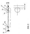
- a ZEMAX ® optical raytrace eye model was created in correspondence with FIG. 2 to assess the predicted spot sizes on the cornea 74 and the retina 76.
- the model contains the laser source 70, the collimating lens 72, and a model (Gullstrand) of a normal eye 75.
- the axial distance from the second surface 72b of the collimating lens 72 to the anterior cornea 74 is 104.92mm.
- the distance from the laser 70 to the collimating lens 72 is 0.735mm.
- Gaussian beam propagation is used to simulate the behavior of the laser beam with a Gaussian cross sectional intensity distribution. A 2 micron input beam waist was assumed.
- Ray trace analysis shows the beam diameter at the cornea at roughly 0.46mm, well within the goal of 1mm or less.
- the size of the spot on the retina, 64 microns, corresponds to an angular range of+/-0.11 degrees exiting the eye.
- h F tan( ⁇ ), where h is the object height, F is the lens focal length (for the eye, this is roughly 17mm), and ⁇ is the field angle.
- the beam approaching the trombone now has an angular subtent of+/-0.11 degrees. Upon exiting the trombone, this is increased to +/-0.12 degrees due to the angular magnification of the trombone.
- the trombone for the specific design at hand is made up of two lenses with focal length ratio of 1.075, thus increasing the angle by that factor.
- the beam now exits the trombone heading toward the lenslet array with an angular spread of ⁇ 0.12 degrees.
- the distance from the back of the eye lens 77 to the retina 76 was lengthened to simulate nearsightedness and shortened to simulate farsightedness.
- the spot size on the retina is even smaller, meaning that for this length eyeball, the retina is closer to the minimum beam waist position.
- the spot on the retina could be as large as 94 microns diameter. This corresponds to 37 micron spots at the wavefront sensor.
- the distance from the laser 70 to the collimating lens 72 can be varied to place the minimum beam waist on the retina 76 for a different case. The solution described above minimizes the spot size for the OD case.
- the spot for the12D patient can get as small as 10 microns, but not without the spot for the +6 diopter patient growing to 95 microns.
- magnification is an important aspect to this approach.
- the lenslet array is an optical system, it will always magnify (or de-magnify) from object to image; in this case, the spot projected onto the retina to the camera sensor.
- the angular spread of the blur spot (Airy spot or the diffraction limited spot) of the lenslet must always be greater than the subtended angle of the, object (the retinal spot).
- the laser injection optics and the wavefront camera imaging optics the lenslet, and to a much lesser degree, the trombone optics
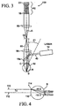
- the illumination component 12 is positioned off-axis relative to the patient's eye 32 as shown schematically in Figure 3.
- Figure 3 shows an overview of a basic Shack-Hartmann aberrometer system 100 for off-axis illumination of the retina R.
- the laser component 12 emits beam 40 towards beamsplitter 16a.
- the illumination component 12 and beamsplitter 16a are positioned such that the light beam 40 impinges the eye 32 off of the optical axis A of the eye.
- a tight beam 41 reflected from the cornea 42 of the eye is reflected off of the optical axis A.
- the remaining light forms a laser beacon B on the retina R of the eye 32.
- the eye's optics propagate a light beam 50 out of the eye that passes through the beamsplitter 16a. Beam 50 then passes through a lens 56, a stop 58 which passes the beam 50 while blocking the beam 41 reflected from the cornea, and a lens 60 to a Hartmann-Shack detector 62.
- the detector 62 comprises the lenslet array 18 to focus the beam 50 as an array of light spots onto a CCD or other suitable two-dimensional detector 22.
- the beam 40 will exhibit the Gaussian characteristics described above for maintaining a retinal spot diameter that remains less than the diffraction limited spot size from the lenslets of the array 18.
- the collimated laser beam 110 is offset laterally from the eye optical axis 112 to direct corneal back reflections 114 out of the wavefront-sensing path.
- an offset, Y of between about 0.5mm to 1mm is suitable with a preferable offset being between about 0.7mm to 1mm.
- the lateral offset, Y. be in the vertical direction (up or down in FIG. 4) due to the fact that the lateral position of the corneal vertex with respect to the geometric center of the pupil will vary from patient to patient. These differences can vary from 0.1mm up to 0.6mm; however, this difference is usually smaller in the vertical direction.
- the position of the spot on the retina, R. will vary as a function of refractive error. As shown in FIG. 4, for a 1mm offset the variation could be up to 0.1mm for far-sighted patients, and 0.21mm for the most near-sighted patient. Angularly, these correspond to 0.34 degrees, and 0.7 degrees, respectively. Therefore, for patients with -4.7 to +4.0 diopters, the spot will be within the foveola (0.5 degree diameter), and all cases will be well within the fovea (5 degree diameter).
- the presence of corneal back reflections at the detector can be detected and the operator can be alerted, accordingly, to make adjustment. This can be done by moving the laser in the instrument, or the entire instrument relative to the patient if it can be moved in sub-millimeter increments. As long as this difference is recorded, it should not upset the mapping of the measured wavefront to the patient's eye.
- An embodiment according to the invention is directed to obtaining a more accurate ocular wavefront aberration measurement with a wavefront-sensing device.
- a retinal illumination source is provided having beam characteristics that eliminate any need to refocus the beam along a propagation path between the illumination source and a patient's eye.
- the beam characteristics are a Gaussian profile with a beam waist that is effectively of constant diameter over the refractive range of the eye, over a refractive range between about +6D to - 12D.
- a retinal illumination beam having a diameter on the eye's retina that is less than a diffraction limit value of an imaging component used to image a portion of the wavefront on a detector over a refractive focus range of the patient's eye between about -12D to +6D.
Landscapes
- Life Sciences & Earth Sciences (AREA)
- Health & Medical Sciences (AREA)
- Medical Informatics (AREA)
- Biophysics (AREA)
- Ophthalmology & Optometry (AREA)
- Engineering & Computer Science (AREA)
- Biomedical Technology (AREA)
- Heart & Thoracic Surgery (AREA)
- Physics & Mathematics (AREA)
- Molecular Biology (AREA)
- Surgery (AREA)
- Animal Behavior & Ethology (AREA)
- General Health & Medical Sciences (AREA)
- Public Health (AREA)
- Veterinary Medicine (AREA)
- Eye Examination Apparatus (AREA)
Description
- The present invention pertains to the field of wave front sensing and, particularly, to an improved ophthalmic aberrometer for retinal illumination.
- A wavefront sensor, often referred to as an aberrometer (which terms will be used interchangeably herein), is a device that measures a difference in the optical path of light between a deformed wavefront and an ideal or reference wavefront. A properly processed measurement yields values for various aberrations in the optical system that the light propagates through. Recent attention has focused on the design and use of wavefront sensors for measuring the aberrations of the eye with the goal of improving visual quality. Williams"
U.S. patent 5,777,719 describes a Shaek-Hartmann type wavefront sensor that can be used to measure, among other parameters, higher-order ocular aberrations. Shack-Hartmann wavefront sensors are characterized by a microlens (lenslet) array for imagining the light reflection from the retina into an array of spots on a detector. The resulting spot image array is displaced from the regular array resulting from an unaberrated optical system. These displacements of the spots are used to determine the wavefront slope at each spot location and this information is typically used to determine the coefficients of Zernike polynomials which represent different orders and modes of the wavefront aberrations. Other types of aberrometers include the spatially resolved refractometer based on the Scheiner optometer, those based on the Tscherning principle, skiascopic systems, scanning systems of the Tracey technology type, raytracing devices, and others. All of these aberrometer types are well known in the ophthalmic wavefront sensing art so that a detailed description of these devices is not necessary to understand the invention. Descriptions of these devices can be found, for example, in J Refractive Surg. 16 (5), September/October 2000. -
DE 199 26 274 discloses a method and apparatus for the simultaneous determination of surface topometry and biometry of the eye. According to the reference, a device and method are disclosed for measuring characteristics of both the anterior corneal surface and an inner surface of the eye utilizing optical coherence topography or wavefront analysis as performed with a Hartmann-Shack detector. - Regardless of the sensing principles of different type aberrometers, they require a retinal illumination source. This is typically a light emitting diode, a superluminescent diode (SLD), a diode laser (typically operated below threshold) or, another, preferably partially-cohereut source that produces a point source on the patient's retina. In fact, it is highly desirable that the eye illumination focus on the eye's fovea so that the ultimate wavefront measurement represents aberrations at the fovea, the highest resolution portion of the retina. Illumination that covers an area larger than the fovea will produce less accurate aberration values. Generally, patient refractive error is the largest optical defect to contend with in aberrometer wavefront measurement. Such error limits the measurement range of the aberrometer. The typical ophthalmic patient will have an uncorrected defocus in a wide range between ±15 diopters (D). This means that the eye will focus light some distance either in front of or behind the retinal plane; producing blurry images on the retina when this value is different from zero.
- De 100 14 480, entitled Customized Corneal Profiling, relates to a system for combining ophthalmic wavefront aberration data and ophthalmic corneal topography data to create a customized ablation correction profile. A portion of the apparatus comprises a wavefront analyser that incorporates a laser diode as the retinal illumination source. The input light is sent through a polarizing beam splitter to ultimately improve the signal to noise ratio of light back-scattered from the retina of the eye that is eventually detected by the lenslet camera of a Hartmann-Shack wavefront detector. A trombone type optical system is used to adjust the focus of the light from the laser diode onto the retina of the eye to correct defocus errors of the eye. Various polarizing optics and phase compensating components are present in the optical path to adjust the beam for optimal performance at the detector.
- Lasers (used herein throughout to refer to the retinal illumination source) used for providing the retinal illumination typically have beam diameters of about 1.5mm, Since the fovea of the eye is also about 1.5mm in diameter, any defocus power in the eye will inhibit a tight match between the illuminating beam and the retinal target. Aberrometers are generally constructed such that their optical systems include refocusing means to account for the patient's refractive power, and also, so that the wavefront image spots are in focus on the wavefront detector. The refocus of the laser beam can be accomplished by injecting it in a position in the aberrometer optical system so that the refocus occurs with the correction of the patient's defocus. Alternatively, a separate focussing optical path can be provided for the illumination light These solutions require that the laser beam pass through refracting optics (lenses). The principal drawback, however, is the noise generated in the wavefront sensor from backscatter due to the inherent disparity in light intensity between the light entering and exiting the eye. For 780nm light, for example, approximately 0.1% of the illumination light is collected for wavefront imaging. The solution provided by polarization optics is too costly to be effective.
- Williams et al
US 6 264 328 discloses a Hartmann-Shack wavefront sensor in which the optical axis of the retinal illumination beam is moved off-axis from the optical axis of the eye being measured. This displacement of the illumination beam path provides separate optical paths for light reflected from the cornea and from the retina of the subject's eye. The corneal reflection can be blocked such that only light reflected and scattered from the subject's retina is directed into the wavefront sensor. The reference also discloses a trombone optical system that is used to adjust the focus of the illumination light input to and exiting from the subject's eye. By adjusting the focus of the light as disclosed therein, defocus errors in the measurement beam introduced by a subject's myopia or hyperopia are eliminated, thus producing a cleaner, stronger signals. - Another concern for accurate wavefront measurement is the compensation of refractive errors on the input side of aberration measurement. One approach for providing a small illumination spot on the fovea was to create a best focus by geometrically correcting the input light by either adding or subtracting optical power from a plane wave. Hence, the input light would diverge or converge to compensate for myopia or hyperopia, respectively. In a myopic eye with a small pupil diameter, however, the input beam is diverging before intercepting the cornea, and the input light profile can take on a significant aberration signature prior to striking the retina. This can seriously degrade the intensity profile distribution which can interject error in localizing (centroiding) the imaged spot on the fovea and, in turn, in the wavefront reconstruction. Moreover, a very small input beam will suffer from diffraction effects and reduce measurement range.
- One solution to this problem is proposed in
International Application WO 00/10448 - Spot asymmetry on the fovea is a further concern affecting accurate wavefront measurement. Poor or inaccurate localization of imaged lenslet spots can create errors in the Zernike polynomial terms of the reconstructed wavefront. Since a Shack-Hartmann device senses a differentiated wavefront, the Zernike terms are no longer mutually independent (i.e., non-orthogonal). As such, system noise can induce Zernike term cross-coupling leading to artificially created Zernike quantities that do not actually exist.
- Accordingly, the inventor has recognized a need for a retinal illumination apparatus in an aberrometer that address the disadvantages of the current technology. These and other advantages and objects of the present invention will become more apparent in view of the following description and figures.
- The invention is defined by the features of claim 1.
- The invention is generally directed to illuminating a patient's retina for making a wavefront measurement with an illumination beam having a beam characteristic, e.g., diameter.or profile, that a) eliminates the need to refocus between the source and the patient's cornea, and b) which maintains a beam spot area on the fovea that is smaller than the diffraction limit of a wavefront imaging component over a defocus range typically encountered in the patient population; i.e., between about -12D to +10D and, preferably, between-12D (±0.25D) to+6D (±0.25D). The improvement is characterized by the aberrometer having an optical path between a retinal illumination source and a patient's eye containing no refractive, diffractive, or other phase altering components. In other words, only beam steering components, if any, are present in the optical path between the retinal illumination source and the patient's eye, Thus, the effective use of Gaussian wave propagation will provide a tight beam waist and a Rayleigh range that extends over a specified refractive error range. The beam diameter of the illumination beam at the patient's anterior cornea is less than 1mm. The retinal illumination source is preferably a 780nm diode laser assembly including an integrated collimating lens; alternatively, a SLD or other source producing coherent or semi-coherent light of a suitable wavelength, plus fixed lens component, may provide the appropriate illumination size and profile. The wavefront imaging component for imaging at least a portion of the unknown wavefront on a detector is preferably a lenslet of o microlens array of a Shack-Hartmann sensor.
- In another embodiment, of making a more accurate wavefront measurement of a patient's eye comprises illuminating the patient's retina with an illumination beam over an optical path between the source and the patient's eye that is free of any refracting, diffracting or phase altering components. An aspect of this embodiment involves providing foveal illumination with a beam diameter that is less than a diffraction limit value of an imaging component that images a portion of the wavefront on a detector over a refractive focus range of the patient's eye between about -12D to +6D. The embodiment further entails providing a Gaussian illumination beam having a Rayleigh range that is greater than the refractive focus range of the patient's eye between about -12D to +6D.
- These and other objects of the present invention will become more readily apparent from the detailed description to follow. However, it should be understood that the detailed description and specific examples, while indicating the preferred embodiments of the invention, are given by way of illustration only, since various changes and modifications within the scope of the invention will become apparent to those skilled in the art based upon the description and drawings herein and the appended claims.
-
- Figure 1 is an optical schematic of a wavefront sensor according to an embodiment of the invention;
- Figure 2 is a schematic diagram showing an illumination component and output retinal illumination beam over a typical range of defocus in the eye according to an embodiment of the invention;
- Figure 3 is an optical schematic of an off-axis illumination system according to the invention; and
- Figure 4 is an optical schematic of an off-axis illumination system according to another embodiment of the invention.
- Figure 1 is an illustration of an improved wavefront sensor in the form of a Shack-
Hartmann aberrometer 10 according to an embodiment of the invention. It will be appreciated that the invention is not limited to a Shack-Hartmann aberrometer, but in fact applies to all aberrometers and wavefront sensing methods that require point source retinal illumination and wavefront imaging for aberration analysis. Generically, anaberrometer 10 requires an optical head, a data acquisition, storage and processing system for detecting, measuring and displaying wavefront aberration data, and interlinking electronics and software. The optical head encompasses anillumination component 12, preferably in the form of a 780nm laserdiode illumination source 70 that outputs a Gaussian, preferably coherent, transverse mode beam and anintegrated collimating lens 72;imaging lenses 14 andbeam splitters 16 for manipulating transmitted and reflected light from theillumination component 12; amicrolens anay 18 an exemplary illustration, λ = 785nm, and f= 6.0mm, d = 0.2mm making each lenslet f/30, and giving a diffraction limit value equal to 57µ. Theillumination component 12 consists oflaser diode 70 andcollimating lens 72 that is fixed in position with respect to thelaser 70. The laser is a 785nm Blue Sky Research CiruLaser Diode (PS108-00) that provides a circularized beam with a total divergence of 10 degrees. The collimatinglens 72 is a Geltech molded asphere 350200 that was chosen due to its short focal length and reasonable cost (available from Thorlabs already coated and mounted).The focal lengh-is chosen so that the laser beam diameter incident on the cornea is very small, 1mm or less, to avoid effects of wavefront error of the eye on the input pass. A ZEMAX® optical raytrace eye model was created in correspondence with FIG. 2 to assess the predicted spot sizes on thecornea 74 and theretina 76. The model contains thelaser source 70, the collimatinglens 72, and a model (Gullstrand) of anormal eye 75. The axial distance from thesecond surface 72b of the collimatinglens 72 to theanterior cornea 74 is 104.92mm. The distance from thelaser 70 to thecollimating lens 72 is 0.735mm. Gaussian beam propagation is used to simulate the behavior of the laser beam with a Gaussian cross sectional intensity distribution. A 2 micron input beam waist was assumed. Ray trace analysis shows the beam diameter at the cornea at roughly 0.46mm, well within the goal of 1mm or less. The size of the spot on the retina, 64 microns, corresponds to an angular range of+/-0.11 degrees exiting the eye. This is calculated using the geometric relationship h = F tan(θ), where h is the object height, F is the lens focal length (for the eye, this is roughly 17mm), and θ is the field angle. The beam approaching the trombone now has an angular subtent of+/-0.11 degrees. Upon exiting the trombone, this is increased to +/-0.12 degrees due to the angular magnification of the trombone. The trombone for the specific design at hand is made up of two lenses with focal length ratio of 1.075, thus increasing the angle by that factor. The beam now exits the trombone heading toward the lenslet array with an angular spread of ±0.12 degrees. As it enters the lenslet array, each lens converts the angular subtent to an image size, using the same equation h = F tan(θ). Since the lenses each have focal length of 6mm, they each create a spot diameter of 2h=2 x 6 mm x tan(0.12 degrees) = 25 microns on the detector. This is significantly smaller than the diffraction spot size for the f/30 lenslets of 57µ. Therefore, due to the trombone magnification and the lenslet focal length, we get spots imaged onto the detector which are smaller than the spot size on the retina. There are several other combinations of trombone magnification and lenslet focal length that would give the same result. For other cases, as described below, the spot size on the retina varies, but is always smaller at the image (detector behind the lenslet array). - To simulate refractive errors, the distance from the back of the
eye lens 77 to theretina 76 was lengthened to simulate nearsightedness and shortened to simulate farsightedness. For the patient with the -12D refractive error, the spot size on the retina is even smaller, meaning that for this length eyeball, the retina is closer to the minimum beam waist position. For the +6D patient, the spot on the retina could be as large as 94 microns diameter. This corresponds to 37 micron spots at the wavefront sensor. The distance from thelaser 70 to thecollimating lens 72 can be varied to place the minimum beam waist on theretina 76 for a different case. The solution described above minimizes the spot size for the OD case. However, as this distance is shortened, the spot for the12D patient can get as small as 10 microns, but not without the spot for the +6 diopter patient growing to 95 microns. - It will be appreciated that stated that the magnification is an important aspect to this approach. Given that the lenslet array is an optical system, it will always magnify (or de-magnify) from object to image; in this case, the spot projected onto the retina to the camera sensor. The angular spread of the blur spot (Airy spot or the diffraction limited spot) of the lenslet must always be greater than the subtended angle of the, object (the retinal spot). Thus one can choose both the laser injection optics and the wavefront camera imaging optics (the lenslet, and to a much lesser degree, the trombone optics) such that this will always be so over the whole refractive error range.
- It is also preferable to keep corneal back-reflections out of the wave front-sensing, path. In an aspect of this embodiment, the
illumination component 12 is positioned off-axis relative to the patient'seye 32 as shown schematically in Figure 3. Figure 3 shows an overview of a basic Shack-Hartmann aberrometer system 100 for off-axis illumination of the retina R. Thelaser component 12 emitsbeam 40 towardsbeamsplitter 16a. Theillumination component 12 andbeamsplitter 16a are positioned such that thelight beam 40 impinges theeye 32 off of the optical axis A of the eye. Thus, atight beam 41 reflected from the cornea 42 of the eye is reflected off of the optical axis A. The remaining light forms a laser beacon B on the retina R of theeye 32. The eye's optics propagate alight beam 50 out of the eye that passes through thebeamsplitter 16a.Beam 50 then passes through alens 56, astop 58 which passes thebeam 50 while blocking thebeam 41 reflected from the cornea, and alens 60 to a Hartmann-Shack detector 62. Thedetector 62 comprises thelenslet array 18 to focus thebeam 50 as an array of light spots onto a CCD or other suitable two-dimensional detector 22. Thebeam 40 will exhibit the Gaussian characteristics described above for maintaining a retinal spot diameter that remains less than the diffraction limited spot size from the lenslets of thearray 18. - In an alternative aspect illustrated with reference to FIG. 4, the collimated
laser beam 110 is offset laterally from the eyeoptical axis 112 to direct cornealback reflections 114 out of the wavefront-sensing path. Based on the typical radius of theanterior cornea surface 116, an offset, Y, of between about 0.5mm to 1mm is suitable with a preferable offset being between about 0.7mm to 1mm. It is also preferable that the lateral offset, Y. be in the vertical direction (up or down in FIG. 4) due to the fact that the lateral position of the corneal vertex with respect to the geometric center of the pupil will vary from patient to patient. These differences can vary from 0.1mm up to 0.6mm; however, this difference is usually smaller in the vertical direction. Due to the lateral offset of the incoming beam, the position of the spot on the retina, R. will vary as a function of refractive error. As shown in FIG. 4, for a 1mm offset the variation could be up to 0.1mm for far-sighted patients, and 0.21mm for the most near-sighted patient. Angularly, these correspond to 0.34 degrees, and 0.7 degrees, respectively. Therefore, for patients with -4.7 to +4.0 diopters, the spot will be within the foveola (0.5 degree diameter), and all cases will be well within the fovea (5 degree diameter). The presence of corneal back reflections at the detector can be detected and the operator can be alerted, accordingly, to make adjustment. This can be done by moving the laser in the instrument, or the entire instrument relative to the patient if it can be moved in sub-millimeter increments. As long as this difference is recorded, it should not upset the mapping of the measured wavefront to the patient's eye. - An embodiment according to the invention is directed to obtaining a more accurate ocular wavefront aberration measurement with a wavefront-sensing device. In one aspect, a retinal illumination source is provided having beam characteristics that eliminate any need to refocus the beam along a propagation path between the illumination source and a patient's eye. The beam characteristics are a Gaussian profile with a beam waist that is effectively of constant diameter over the refractive range of the eye, over a refractive range between about +6D to - 12D. In a related aspect, it is preferable to provide a retinal illumination beam having a diameter on the eye's retina that is less than a diffraction limit value of an imaging component used to image a portion of the wavefront on a detector over a refractive focus range of the patient's eye between about -12D to +6D.
- While various advantageous embodiments have been chosen to illustrate the invention, it will be understood by those skilled in the art that changes and modifications can be made therein without departing from the scope of the invention as defined in the appended claims.
Claims (8)
- A wavefront sensing device (10) for measuring an aberrated wavefront from a patient's eye (32), said device comprising an optical head including a retinal illumination component (12), a data acquisition, storage and processing system (24) including a lenslet array (18) for imaging the aberrated wavefront on a detector (20), and interlinking electronics integrated to detect, measure and display ocular aberration information, wherein the retinal illumination component (12) provides a collimated retinal illumination beam (40) having a Gaussian beam characteristic,
characterized in that:the illumination component consists of a a laser diode or a super luminescent diode (70) and an integrated, fixedly positioned-collimating lens (72),there are no refractive, diffractive or optical phase altering components along an optical path between the illumination component (12) and a proposed location of the surface (74) of the patient's eye being measured, the collimated beam has a diameter, d, at the surface (74) of a patients eye, where d <1 mm. - The device of claim 1, wherein the light source emits a wavelength in the range of about 780nm to 800mm. and wherein the beam has a Rayleigh range that is equal to or greater than an ocular refractive power range of the patient's eye between about12D to +6D, being calculated using a focal length of the patient's eye of 17 mm.
- The device of claim 1, wherein the device has an optical measurement axis, further wherein the retinal illumination beam has an optical axis that is displaced from the optical measurement axis of the device.
- The device of claim 3, wherein the displacement is a parallel translation of between about 0.6mm and 1.0mm
- The device of claim 1, further characterized in that an angular spread of a blur spot of a lenslet of the lenslet array is greater than a subtended angle of an object illumination spot formed by the laser beam.
- The device of claim 1, wherein the device is a Shack-Hartmann wavefront sensor.
- The device of claim 1, wherein the collimated beam has a diameter, d, at the proposed location of the surface (74) of the patient's eye, where d <1mm.
- The device of claim 7, wherein 0.46mm < d < 1mm.
Applications Claiming Priority (3)
| Application Number | Priority Date | Filing Date | Title |
|---|---|---|---|
| US27377 | 1996-09-26 | ||
| US10/027,377 US6736509B2 (en) | 2001-12-21 | 2001-12-21 | Aberrometer illumination apparatus and method |
| PCT/US2002/040067 WO2003055380A2 (en) | 2001-12-21 | 2002-12-13 | Aberrometer illumination apparatus and method |
Publications (2)
| Publication Number | Publication Date |
|---|---|
| EP1458280A2 EP1458280A2 (en) | 2004-09-22 |
| EP1458280B1 true EP1458280B1 (en) | 2007-10-17 |
Family
ID=21837380
Family Applications (1)
| Application Number | Title | Priority Date | Filing Date |
|---|---|---|---|
| EP02805942A Expired - Lifetime EP1458280B1 (en) | 2001-12-21 | 2002-12-13 | Aberrometer |
Country Status (10)
| Country | Link |
|---|---|
| US (1) | US6736509B2 (en) |
| EP (1) | EP1458280B1 (en) |
| JP (1) | JP4206338B2 (en) |
| KR (1) | KR100925526B1 (en) |
| CN (1) | CN100469307C (en) |
| AU (1) | AU2002357237B2 (en) |
| CA (1) | CA2471037C (en) |
| DE (1) | DE60223075T2 (en) |
| ES (1) | ES2294206T3 (en) |
| WO (1) | WO2003055380A2 (en) |
Families Citing this family (25)
| Publication number | Priority date | Publication date | Assignee | Title |
|---|---|---|---|---|
| DE10224363A1 (en) * | 2002-05-24 | 2003-12-04 | Zeiss Carl Smt Ag | Methods for determining wavefront aberrations |
| US7556378B1 (en) | 2003-04-10 | 2009-07-07 | Tsontcho Ianchulev | Intraoperative estimation of intraocular lens power |
| US7706863B2 (en) | 2004-01-21 | 2010-04-27 | University Of Washington | Methods for assessing a physiological state of a mammalian retina |
| ES2665536T3 (en) | 2004-04-20 | 2018-04-26 | Alcon Research, Ltd. | Integrated surgical microscope and wavefront sensor |
| US20060126019A1 (en) * | 2004-12-10 | 2006-06-15 | Junzhong Liang | Methods and systems for wavefront analysis |
| US20060126018A1 (en) * | 2004-12-10 | 2006-06-15 | Junzhong Liang | Methods and apparatus for wavefront sensing of human eyes |
| US9192296B2 (en) | 2007-08-21 | 2015-11-24 | Visionix Ltd. | Multifunctional ophthalmic measurement system |
| US8157378B2 (en) * | 2007-08-23 | 2012-04-17 | Bausch & Lomb Incorporated | Eye illumination apparatus and method |
| DE102007043390B4 (en) | 2007-09-12 | 2018-08-30 | Uvex Arbeitsschutz Gmbh | Method and apparatus for the production of protective goggles with a visually non-correcting lens and goggles subsequently produced |
| US8333474B2 (en) | 2007-10-19 | 2012-12-18 | Wavetec Vision Systems, Inc. | Optical instrument alignment system |
| US7594729B2 (en) | 2007-10-31 | 2009-09-29 | Wf Systems, Llc | Wavefront sensor |
| EP2306889A4 (en) * | 2008-07-10 | 2012-11-28 | Univ Indiana Res & Tech Corp | OPHTHALMIC DEVICES, SYSTEMS AND METHOD |
| US8550624B2 (en) | 2008-11-06 | 2013-10-08 | Wavetec Vision Systems, Inc. | Optical angular measurement system for ophthalmic applications and method for positioning of a toric intraocular lens with increased accuracy |
| US8254724B2 (en) | 2008-11-06 | 2012-08-28 | Bausch & Lomb Incorporated | Method and apparatus for making and processing aberration measurements |
| US7980698B2 (en) | 2008-11-19 | 2011-07-19 | Bausch & Lomb Incorporated | Power-adjusted aberrometer |
| US8876290B2 (en) | 2009-07-06 | 2014-11-04 | Wavetec Vision Systems, Inc. | Objective quality metric for ocular wavefront measurements |
| EP2818130B1 (en) * | 2009-07-14 | 2017-09-27 | WaveTec Vision Systems, Inc. | Determination of the effective lens position of an intraocular lens using aphakic refractive power |
| CN102497833B (en) | 2009-07-14 | 2014-12-03 | 波技术视觉系统公司 | Ophthalmic surgery measurement system |
| US8985768B2 (en) * | 2011-11-25 | 2015-03-24 | Ming Lai | Integrated refractor |
| EP2833778B1 (en) | 2012-04-05 | 2022-05-18 | Visionix Ltd. | Objective phoropter system |
| EP2872030B1 (en) * | 2012-07-10 | 2016-12-07 | WaveLight GmbH | Process and apparatus for determining optical aberrations of an eye |
| US9072462B2 (en) | 2012-09-27 | 2015-07-07 | Wavetec Vision Systems, Inc. | Geometric optical power measurement device |
| US9538911B2 (en) * | 2013-09-19 | 2017-01-10 | Novartis Ag | Integrated OCT-refractometer system for ocular biometry |
| JP6779910B2 (en) | 2015-05-05 | 2020-11-04 | ビジョニックス リミテッド | Accuracy-improving object phoropter |
| EP3928683A1 (en) | 2020-06-24 | 2021-12-29 | Carl Zeiss Vision International GmbH | Device and method for determining at least one ocular aberration |
Family Cites Families (10)
| Publication number | Priority date | Publication date | Assignee | Title |
|---|---|---|---|---|
| US6271914B1 (en) | 1996-11-25 | 2001-08-07 | Autonomous Technologies Corporation | Objective measurement and correction of optical systems using wavefront analysis |
| US5777719A (en) | 1996-12-23 | 1998-07-07 | University Of Rochester | Method and apparatus for improving vision and the resolution of retinal images |
| US6598975B2 (en) | 1998-08-19 | 2003-07-29 | Alcon, Inc. | Apparatus and method for measuring vision defects of a human eye |
| PT1105037E (en) | 1998-08-19 | 2002-11-29 | Autonomous Technologies Corp | APPARATUS AND METHOD FOR MEASURING VISION DEFECTS OF A HUMAN EYE |
| DE19926274A1 (en) | 1999-06-09 | 2001-01-04 | Benedikt Jean | Eye shape and performance measurement concurrently uses Placido Topometer and wavefront analyzer to measure eye |
| DE69906779T2 (en) * | 1998-11-13 | 2004-01-29 | Jean Benedikt | METHOD AND DEVICE FOR SIMULTANEOUS DETECTION OF SURFACE OPOGRAPHY AND BIOMETRY OF AN EYE |
| US6050687A (en) | 1999-06-11 | 2000-04-18 | 20/10 Perfect Vision Optische Geraete Gmbh | Method and apparatus for measurement of the refractive properties of the human eye |
| US6264328B1 (en) | 1999-10-21 | 2001-07-24 | University Of Rochester | Wavefront sensor with off-axis illumination |
| DE10014480A1 (en) | 2000-03-23 | 2001-09-27 | Technolas Gmbh | Eye refractive profile developing method for ophthalmic refractive surgery, involves developing refractive course of treatment of eye from determined corneal topography and wavefront aberration |
| US6460997B1 (en) * | 2000-05-08 | 2002-10-08 | Alcon Universal Ltd. | Apparatus and method for objective measurements of optical systems using wavefront analysis |
-
2001
- 2001-12-21 US US10/027,377 patent/US6736509B2/en not_active Expired - Lifetime
-
2002
- 2002-12-13 CN CNB028256484A patent/CN100469307C/en not_active Expired - Fee Related
- 2002-12-13 EP EP02805942A patent/EP1458280B1/en not_active Expired - Lifetime
- 2002-12-13 WO PCT/US2002/040067 patent/WO2003055380A2/en not_active Ceased
- 2002-12-13 AU AU2002357237A patent/AU2002357237B2/en not_active Ceased
- 2002-12-13 JP JP2003555959A patent/JP4206338B2/en not_active Expired - Fee Related
- 2002-12-13 ES ES02805942T patent/ES2294206T3/en not_active Expired - Lifetime
- 2002-12-13 KR KR1020047009686A patent/KR100925526B1/en not_active Expired - Fee Related
- 2002-12-13 DE DE60223075T patent/DE60223075T2/en not_active Expired - Lifetime
- 2002-12-13 CA CA002471037A patent/CA2471037C/en not_active Expired - Fee Related
Also Published As
| Publication number | Publication date |
|---|---|
| JP2005514087A (en) | 2005-05-19 |
| JP4206338B2 (en) | 2009-01-07 |
| EP1458280A2 (en) | 2004-09-22 |
| DE60223075T2 (en) | 2008-07-17 |
| US6736509B2 (en) | 2004-05-18 |
| WO2003055380A3 (en) | 2003-12-11 |
| AU2002357237B2 (en) | 2007-07-05 |
| AU2002357237A1 (en) | 2003-07-15 |
| KR20040088033A (en) | 2004-10-15 |
| DE60223075D1 (en) | 2007-11-29 |
| CN100469307C (en) | 2009-03-18 |
| CN1606422A (en) | 2005-04-13 |
| ES2294206T3 (en) | 2008-04-01 |
| HK1076996A1 (en) | 2006-02-03 |
| CA2471037C (en) | 2008-07-15 |
| CA2471037A1 (en) | 2003-07-10 |
| US20030117581A1 (en) | 2003-06-26 |
| KR100925526B1 (en) | 2009-11-05 |
| WO2003055380A2 (en) | 2003-07-10 |
Similar Documents
| Publication | Publication Date | Title |
|---|---|---|
| US6736509B2 (en) | Aberrometer illumination apparatus and method | |
| AU2004231509B2 (en) | Moire aberrometer | |
| JP3452860B2 (en) | A device for measuring the refractive properties of the human eye | |
| US7988290B2 (en) | Systems and methods for measuring the shape and location of an object | |
| US6273566B1 (en) | Ophthalmologic characteristic measuring apparatus | |
| US20080316429A1 (en) | Method and apparatus improving vision and the resolution of retinal images | |
| US10575725B2 (en) | System and method for characterising eye-related systems | |
| US20060126018A1 (en) | Methods and apparatus for wavefront sensing of human eyes | |
| EP1602320B1 (en) | Ophthalmic apparatus | |
| EP1455638B1 (en) | Improved sequential scanning wavefront measurement and retinal topography | |
| US20250204774A1 (en) | Method and Device for Wave Front Measurement in the Human Eye | |
| US6676258B2 (en) | Eye characteristic measurement apparatus with speckle noise reduction | |
| HK1076996B (en) | A wavefront-sensing device | |
| Ko et al. | Optics of refractometers for refractive power measurement of the human eye | |
| WO2015049632A1 (en) | Apparatus and method for measuring aberrations of the optical system of a living being |
Legal Events
| Date | Code | Title | Description |
|---|---|---|---|
| PUAI | Public reference made under article 153(3) epc to a published international application that has entered the european phase |
Free format text: ORIGINAL CODE: 0009012 |
|
| 17P | Request for examination filed |
Effective date: 20040719 |
|
| AK | Designated contracting states |
Kind code of ref document: A2 Designated state(s): AT BE BG CH CY CZ DE DK EE ES FI FR GB GR IE IT LI LU MC NL PT SE SI SK TR |
|
| AX | Request for extension of the european patent |
Extension state: AL LT LV MK RO |
|
| 17Q | First examination report despatched |
Effective date: 20050509 |
|
| GRAP | Despatch of communication of intention to grant a patent |
Free format text: ORIGINAL CODE: EPIDOSNIGR1 |
|
| RTI1 | Title (correction) |
Free format text: ABERROMETER |
|
| GRAS | Grant fee paid |
Free format text: ORIGINAL CODE: EPIDOSNIGR3 |
|
| GRAA | (expected) grant |
Free format text: ORIGINAL CODE: 0009210 |
|
| AK | Designated contracting states |
Kind code of ref document: B1 Designated state(s): DE ES FR GB IT |
|
| REG | Reference to a national code |
Ref country code: GB Ref legal event code: FG4D |
|
| REF | Corresponds to: |
Ref document number: 60223075 Country of ref document: DE Date of ref document: 20071129 Kind code of ref document: P |
|
| REG | Reference to a national code |
Ref country code: ES Ref legal event code: FG2A Ref document number: 2294206 Country of ref document: ES Kind code of ref document: T3 |
|
| ET | Fr: translation filed | ||
| PLBE | No opposition filed within time limit |
Free format text: ORIGINAL CODE: 0009261 |
|
| STAA | Information on the status of an ep patent application or granted ep patent |
Free format text: STATUS: NO OPPOSITION FILED WITHIN TIME LIMIT |
|
| 26N | No opposition filed |
Effective date: 20080718 |
|
| REG | Reference to a national code |
Ref country code: FR Ref legal event code: PLFP Year of fee payment: 14 |
|
| REG | Reference to a national code |
Ref country code: FR Ref legal event code: PLFP Year of fee payment: 15 |
|
| REG | Reference to a national code |
Ref country code: FR Ref legal event code: PLFP Year of fee payment: 16 |
|
| PGFP | Annual fee paid to national office [announced via postgrant information from national office to epo] |
Ref country code: FR Payment date: 20171120 Year of fee payment: 16 |
|
| PGFP | Annual fee paid to national office [announced via postgrant information from national office to epo] |
Ref country code: GB Payment date: 20171128 Year of fee payment: 16 Ref country code: IT Payment date: 20171218 Year of fee payment: 16 |
|
| PGFP | Annual fee paid to national office [announced via postgrant information from national office to epo] |
Ref country code: ES Payment date: 20180105 Year of fee payment: 16 Ref country code: DE Payment date: 20171221 Year of fee payment: 16 |
|
| REG | Reference to a national code |
Ref country code: DE Ref legal event code: R119 Ref document number: 60223075 Country of ref document: DE |
|
| GBPC | Gb: european patent ceased through non-payment of renewal fee |
Effective date: 20181213 |
|
| PG25 | Lapsed in a contracting state [announced via postgrant information from national office to epo] |
Ref country code: FR Free format text: LAPSE BECAUSE OF NON-PAYMENT OF DUE FEES Effective date: 20181231 Ref country code: DE Free format text: LAPSE BECAUSE OF NON-PAYMENT OF DUE FEES Effective date: 20190702 Ref country code: IT Free format text: LAPSE BECAUSE OF NON-PAYMENT OF DUE FEES Effective date: 20181213 |
|
| PG25 | Lapsed in a contracting state [announced via postgrant information from national office to epo] |
Ref country code: GB Free format text: LAPSE BECAUSE OF NON-PAYMENT OF DUE FEES Effective date: 20181213 |
|
| REG | Reference to a national code |
Ref country code: ES Ref legal event code: FD2A Effective date: 20200203 |
|
| PG25 | Lapsed in a contracting state [announced via postgrant information from national office to epo] |
Ref country code: ES Free format text: LAPSE BECAUSE OF NON-PAYMENT OF DUE FEES Effective date: 20181214 |