EP1458169A2 - Bar type portable wireless terminal - Google Patents
Bar type portable wireless terminal Download PDFInfo
- Publication number
- EP1458169A2 EP1458169A2 EP04005639A EP04005639A EP1458169A2 EP 1458169 A2 EP1458169 A2 EP 1458169A2 EP 04005639 A EP04005639 A EP 04005639A EP 04005639 A EP04005639 A EP 04005639A EP 1458169 A2 EP1458169 A2 EP 1458169A2
- Authority
- EP
- European Patent Office
- Prior art keywords
- portable wireless
- wireless terminal
- lower body
- bar type
- type portable
- Prior art date
- Legal status (The legal status is an assumption and is not a legal conclusion. Google has not performed a legal analysis and makes no representation as to the accuracy of the status listed.)
- Withdrawn
Links
Images


Classifications
-
- H—ELECTRICITY
- H04—ELECTRIC COMMUNICATION TECHNIQUE
- H04N—PICTORIAL COMMUNICATION, e.g. TELEVISION
- H04N1/00—Scanning, transmission or reproduction of documents or the like, e.g. facsimile transmission; Details thereof
- H04N1/21—Intermediate information storage
- H04N1/2104—Intermediate information storage for one or a few pictures
- H04N1/2112—Intermediate information storage for one or a few pictures using still video cameras
-
- H—ELECTRICITY
- H04—ELECTRIC COMMUNICATION TECHNIQUE
- H04B—TRANSMISSION
- H04B1/00—Details of transmission systems, not covered by a single one of groups H04B3/00 - H04B13/00; Details of transmission systems not characterised by the medium used for transmission
- H04B1/38—Transceivers, i.e. devices in which transmitter and receiver form a structural unit and in which at least one part is used for functions of transmitting and receiving
- H04B1/40—Circuits
-
- H—ELECTRICITY
- H04—ELECTRIC COMMUNICATION TECHNIQUE
- H04N—PICTORIAL COMMUNICATION, e.g. TELEVISION
- H04N7/00—Television systems
- H04N7/14—Systems for two-way working
- H04N7/141—Systems for two-way working between two video terminals, e.g. videophone
- H04N7/142—Constructional details of the terminal equipment, e.g. arrangements of the camera and the display
- H04N2007/145—Handheld terminals
Definitions
- the present invention relates to a portable wireless terminal, and more particularly to a bar type portable wireless terminal, which involves the complex functions of PDA, portable phone, digital imaging device and so on.
- portable wireless terminals are classified into bar type terminals, flip type terminals and folder type terminals, in accordance with an external form thereof.
- the bar type terminals are configured so that a single body housing thereof is provided with a keypad as data input means, a display device as data output means, and receiver and transmitter modules. Such a bar type terminal has an advantage that its entire construction is simple.
- the flip type terminals generally comprise a terminal body, a flip cover, and a hinge mechanism adapted to rotatably couple the flip cover to the terminal body.
- the terminal body of the flip type terminal is configured in the same manner as that of the bar type terminal, the flip cover is adapted to cover a keypad provided on the terminal body when the terminal is in a call waiting mode.
- the flip type terminal has an advantage that it can prevent the malfunctioning of the keypad.
- the folder type terminals generally comprise a terminal body, a folder, and a hinge mechanism adapted to rotatably couple the folder to the terminal body.
- the folder is adapted to be opened away from or closed to the terminal body according to its rotation relative to the terminal body. ln a call waiting mode wherein the folder is folded to come into close contact with the terminal body, the folder is adapted to cover a keypad provided on the terminal body, thereby preventing the malfunctioning of the keypad. Further, in a conversation mode wherein the folder is unfolded to a certain opened position, the portable wireless terminal is adapted to ensure a sufficient distance between transmitter and receiver modules, thereby advantageously achieving miniaturization thereof.
- the present invention has been made in view of the above problems, and it is an object of the present invention to provide a portable wireless terminal, which can provide a broad range of rapidly developing mobile communication services.
- a bar type portable wireless terminal comprising: a lower body installed at a first side surface with a camera lens unit, and a second side surface with an image reproduction device adapted to output images captured by the camera lens unit; and an upper body coupled to an upper end of the lower body so that it is rotatable in a twisting direction relative to a rotation axis extending in a longitudinal direction of the lower body, the upper body being installed at its front surface with a display device adapted to enable the output of the images captured by the camera lens unit.
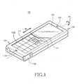
- Fig. 1 is a perspective view illustrating a bar type portable wireless terminal, designated as a reference numeral 100, in accordance with a preferred embodiment of the present invention.
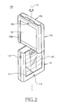
- Fig. 2 is a perspective view illustrating a state wherein an upper body, designated as a reference numeral 102, of the terminal 100 shown in Fig.1 is rotated.
- Fig. 3 is a perspective view illustrating sliding movements of a slidable cover, designated as a reference numeral 123, provided in the terminal 100 shown in Fig. 1.
- the portable wireless terminal 100 according to the preferred embodiment of the present invention is a bar type terminal comprising a lower body 101 and upper body 102.
- the upper body 102 is rotatably coupled to an upper end of the lower body 101.
- the lower body 101 is provided at its front surface with a keypad 111 and transmitter 113, containing a microphone, below the keypad 111.
- the lower body 101 is also provided at a first side surface with a camera lens unit 115 and a second side surface with an image reproduction device 117.
- the camera lens unit 115 shown in Fig. 2, is installed inside the lower body 101 in such a fashion that its exposure window faces a sideward direction of the lower body 101.
- the image reproduction device 117 shown in Fig. 4, serves to reproduce images captured by the camera lens unit 115.
- the image reproduction device 117 is adapted to be protected by a protective cover 119a or 119b, except during image reproduction.
- Fig. 6 illustrates a rotary type protective cover 119a, which is rotatably coupled to one side end of the image reproduction device 117 relative to a rotation axis A2.
- Fig. 7 illustrates a sliding type protective cover 119b, which is adapted to slidably reciprocate in a direction of arrow B2.
- the upper body 102 is rotatably coupled to the upper end of the lower body 101 such that the upper body 102 is rotatable in a twisting direction relative to the rotation axis A2 extending in a longitudinal direction of the lower body 101.
- the upper body 102 is provided at its front surface with a display device 121, and a receiver 125, containing a speakerphone, above the display device 121.
- the display device 121 is preferably embodied as a touch screen, and adapted to display images captured by the camera lens unit 115.
- the upper body 102 is also provided at its upper end surface with a MMC (man machine communication) slot 104.
- MMC man machine communication
- the MMC slot 104 is provided therein with an ear-microphone jack 143 and a multi-connector 145.
- the multi-connector 145 enables the portable wireless terminal 100 to be connected to a personal computer, external storage device, and so on.
- the MMC slot 104 is adapted to be protected by a slot cover 141 rotatably coupled thereto relative to a rotation axis A3 extending in a transverse direction of the terminal 100.
- the slot cover 141 serves to prevent impurities from entering the ear-microphone jack 143 or multi-connector 145.
- the slot cover 141 may be constructed as a sliding type cover.
- Lower and upper bodies 101 and 102 of the terminal 100 are formed with first and second sliding guides 103a and 103b, respectively.
- the first sliding guides 103a extend along both longitudinal edges of the display device 121
- the second sliding guides 103b extend along both longitudinal edges of the keypad 111. Where the keypad 111 and display device 121 face the same direction, i.e. when the lower and upper bodies 101 and 102 are not rotated, the first sliding guides 103a are aligned with the second sliding guides 103b.
- the terminal 100 is provided at its front surface with a slidable cover 123, which is adapted to move slidably along the first and second sliding guides 103a and 103b.
- the slidable cover 123 is movable in a direction of arrow B1, shown in Figs. 1 and 3, along the first and second sliding guides 103a and 103b.
- the slidable cover 123 is made of transparent materials such as glass and acrylic.
- Fig. 1 illustrates a state wherein the slidable cover 123 is positioned on the display device 121
- Fig. 1 illustrates a state wherein the slidable cover 123 is positioned on the display device 121
- FIG. 2 illustrates a state wherein the slidable cover 123 is positioned on the keypad 111.
- the slidable cover 123 has to be fixed when it is positioned on the keypad 111.
- the slidable cover 123 has a length shorter than the lengths of the respective first and second sliding guides 103a and 103b, the upper body 102 is adapted to freely rotate regardless of a position of the slidable cover 123. ln this way, the slidable cover 123 also functions to selectively limit the manipulation of the terminal 100, in addition to its protective function. That it to say, when the slidable cover 123 is positioned on the upper body 102, a user is allowed to manipulate the terminal 100 or input data only through the keypad 111.
- the touch screen is operable as a PDA terminal mode enabling data input using a pen.
- the terminal 100 is manipulated for an image capturing purpose or a data input purpose using the touch screen and pen in a state wherein the slidable cover 123 is positioned on the lower body 101, it is possible to prevent the malfunctioning of the keypad 111.
- the slidable cover 123 functions as an operation conversion switch.
- Fig. 4 is a perspective view illustrating a state wherein the terminal 100 shown in Fig. 1 is used as a digital imaging device.
- the upper body 102 of the terminal 100 is shown in Fig. 4 with the lower body 101 rotated at 90° about the rotation axis A1, and the slidable cover 123 is positioned on the keypad 111.
- the camera lens unit 115 is used to capture images and the captured images can be displayed selectively on the image reproduction device 117 or display device 121.
- the portable wireless terminal 100 can be utilized as a digital camera as well as the digital imaging device.
- the upper body 102 is provided at its one side surface with a shutter button 126 (shown in Fig. 3).
- the shutter button 126 may be substituted with one selected from among key buttons on the keypad 111 of the lower body 101, in accordance with the arrangement of the sliding cover 123 and sliding guides, 103a and 103b.
- the terminal 100 is configured to enable a user to edit the images captured by the camera lens unit 115 in real time while confirming them through the image reproduction device 117.
- the display device 121 is preferably constructed as a touch screen which can be set to display an image edition menu when the terminal 100 is operated as the digital imaging device.
- the terminal 100 is adapted to be connected to certain external devices through the multi-connector 145 installed at the upper body 102, thereby ensuring a sufficient storage capacity required to store the captured images.
- an image capturing direction of the camera lens unit 115 and an image display direction of the display device 121 are appropriately set, e.g. set in the same plane, a user can conveniently perform video communications using the terminal 100.
- a portable wireless terminal of the present invention can be used as a digital image device according to requirements of a user, as well as functioning as a portable phone, PDA and so on.
- the portable wireless terminal in accordance with the present invention has an advantage that it can function as a multimedia device as well as a mobile communication terminal.
- the portable wireless terminal is used as the multimedia device, the user can conveniently use it without a limitation of storage capacity since it is configured to be easily connected to certain external devices using a multi-connector provided therein.
- the portable wireless terminal is configured to allow the user to directly edit the captured images using a display device constructed as a touch screen while confirming the images using an image reproduction device thereof. This improves a convenience of use as the multimedia device.
Abstract
Description
- The present invention relates to a portable wireless terminal, and more particularly to a bar type portable wireless terminal, which involves the complex functions of PDA, portable phone, digital imaging device and so on.
- Generally, portable wireless terminals are classified into bar type terminals, flip type terminals and folder type terminals, in accordance with an external form thereof.
- The bar type terminals are configured so that a single body housing thereof is provided with a keypad as data input means, a display device as data output means, and receiver and transmitter modules. Such a bar type terminal has an advantage that its entire construction is simple.
- The flip type terminals generally comprise a terminal body, a flip cover, and a hinge mechanism adapted to rotatably couple the flip cover to the terminal body. Although the terminal body of the flip type terminal is configured in the same manner as that of the bar type terminal, the flip cover is adapted to cover a keypad provided on the terminal body when the terminal is in a call waiting mode. Thus, the flip type terminal has an advantage that it can prevent the malfunctioning of the keypad.
- The folder type terminals generally comprise a terminal body, a folder, and a hinge mechanism adapted to rotatably couple the folder to the terminal body. The folder is adapted to be opened away from or closed to the terminal body according to its rotation relative to the terminal body. ln a call waiting mode wherein the folder is folded to come into close contact with the terminal body, the folder is adapted to cover a keypad provided on the terminal body, thereby preventing the malfunctioning of the keypad. Further, in a conversation mode wherein the folder is unfolded to a certain opened position, the portable wireless terminal is adapted to ensure a sufficient distance between transmitter and receiver modules, thereby advantageously achieving miniaturization thereof.
- Meanwhile, as mobile services become increasingly diversified, their utilization range expands to various uses including motion picture providing services, video communications, and financial services, as well as conventional short message services and voice communications.
- According to this trend, various add-ons such as a camera lens and so on are installed to conventional portable wireless terminals, but there is a problem that the conventional portable wireless terminals can't sufficiently satisfy diverse mobile communication services and options. ln addition, as the use of the portable wireless terminals becomes universalized, customers require a wider range of the portable wireless terminals, in accordance with a variety of standards including designs and functions thereof. However, the conventional terminals can't sufficiently reflect such diverse customers' requirements via a single terminal.
- Therefore, the present invention has been made in view of the above problems, and it is an object of the present invention to provide a portable wireless terminal, which can provide a broad range of rapidly developing mobile communication services.
- It is another object of the present invention to provide a portable wireless terminal, which has an advantage of being configured to accommodate an expanding range of the portable wireless service options in accordance with customers' increasingly diversified requirements.
- It is yet another object of the present invention to provide a portable wireless terminal, which is structured simply so as to allow a user to easily access such wide range of mobile communication services, options and content while providing reliable operation.
- These objects are solved with the bar type portable wireless terminal according to
claim 1. - ln accordance with one aspect of the present invention, the above and other objects can be accomplished by the provision of a bar type portable wireless terminal comprising: a lower body installed at a first side surface with a camera lens unit, and a second side surface with an image reproduction device adapted to output images captured by the camera lens unit; and an upper body coupled to an upper end of the lower body so that it is rotatable in a twisting direction relative to a rotation axis extending in a longitudinal direction of the lower body, the upper body being installed at its front surface with a display device adapted to enable the output of the images captured by the camera lens unit.
Further advantageous embodiments are according to the dependent claims. - The above and other objects, features and other advantages of the present invention will be more clearly understood from the following detailed description taken in conjunction with the accompanying drawings, in which:
- Fig. 1 is a perspective view illustrating a bar type portable wireless terminal in accordance with a preferred embodiment of the present invention;
- Fig. 2 is a perspective view illustrating a state wherein an upper body of the terminal shown in Fig. 1 is rotated;
- Fig. 3 is a perspective view illustrating sliding movements of a slidable cover provided in the terminal shown in Fig. 1;
- Fig. 4 is a perspective view illustrating a state wherein the terminal shown in Fig. 1 is used as a digital imaging device;
- Fig. 5 is a perspective view illustrating a MMC slot of the terminal shown in Fig. 1;
- Fig. 6 is a perspective view illustrating a protective cover of an image reproduction device of the terminal shown in Fig. 1; and
- Fig. 7 is a perspective view illustrating another type protective cover of the image reproduction device of the terminal shown in Fig. 1.
-
- Now, preferred embodiments of the present invention will be described in detail with reference to the annexed drawings. In the drawings, the same or similar elements are denoted by the same reference numerals even though they are depicted in different drawings. ln the following description, a detailed description of known functions and configurations incorporated herein will be omitted to avoid obscuring the subject matter of the present invention with unnecessary detail. Also, the terms used in the following description are terms defined taking into consideration the functions obtained in accordance with the present invention. The definitions of these terms should be determined based on the whole content of this specification because it may be changed in accordance with the option of a user or within usual practice.
- Fig. 1 is a perspective view illustrating a bar type portable wireless terminal, designated as a
reference numeral 100, in accordance with a preferred embodiment of the present invention. Fig. 2 is a perspective view illustrating a state wherein an upper body, designated as areference numeral 102, of theterminal 100 shown in Fig.1 is rotated. Fig. 3 is a perspective view illustrating sliding movements of a slidable cover, designated as areference numeral 123, provided in theterminal 100 shown in Fig. 1. As shown in Figs. 1 to 3, the portablewireless terminal 100 according to the preferred embodiment of the present invention is a bar type terminal comprising alower body 101 andupper body 102. Theupper body 102 is rotatably coupled to an upper end of thelower body 101. - The
lower body 101 is provided at its front surface with akeypad 111 andtransmitter 113, containing a microphone, below thekeypad 111. Thelower body 101 is also provided at a first side surface with acamera lens unit 115 and a second side surface with animage reproduction device 117. Thecamera lens unit 115, shown in Fig. 2, is installed inside thelower body 101 in such a fashion that its exposure window faces a sideward direction of thelower body 101. Theimage reproduction device 117, shown in Fig. 4, serves to reproduce images captured by thecamera lens unit 115. - Referring to Figs. 6 and 7, the
image reproduction device 117 is adapted to be protected by aprotective cover protective cover 119a, which is rotatably coupled to one side end of theimage reproduction device 117 relative to a rotation axis A2. Fig. 7 illustrates a sliding typeprotective cover 119b, which is adapted to slidably reciprocate in a direction of arrow B2. - Referring to Figs. 1 to 3, the
upper body 102 is rotatably coupled to the upper end of thelower body 101 such that theupper body 102 is rotatable in a twisting direction relative to the rotation axis A2 extending in a longitudinal direction of thelower body 101. Theupper body 102 is provided at its front surface with adisplay device 121, and areceiver 125, containing a speakerphone, above thedisplay device 121. Thedisplay device 121 is preferably embodied as a touch screen, and adapted to display images captured by thecamera lens unit 115. - The
upper body 102 is also provided at its upper end surface with a MMC (man machine communication)slot 104. Referring to Fig. 5 illustrating theMMC slot 104 in detail, theMMC slot 104 is provided therein with an ear-microphone jack 143 and a multi-connector 145. The multi-connector 145 enables the portablewireless terminal 100 to be connected to a personal computer, external storage device, and so on. TheMMC slot 104 is adapted to be protected by aslot cover 141 rotatably coupled thereto relative to a rotation axis A3 extending in a transverse direction of theterminal 100. Theslot cover 141 serves to prevent impurities from entering the ear-microphone jack 143 or multi-connector 145. Although not shown, theslot cover 141 may be constructed as a sliding type cover. - Lower and
upper bodies terminal 100 are formed with first and secondsliding guides sliding guides 103a extend along both longitudinal edges of thedisplay device 121, and the secondsliding guides 103b extend along both longitudinal edges of thekeypad 111. Where thekeypad 111 anddisplay device 121 face the same direction, i.e. when the lower andupper bodies sliding guides 103a are aligned with the secondsliding guides 103b. - The
terminal 100 is provided at its front surface with aslidable cover 123, which is adapted to move slidably along the first and secondsliding guides slidable cover 123 is movable in a direction of arrow B1, shown in Figs. 1 and 3, along the first and secondsliding guides display device 121 while allowing a user to look at information displayed on thedisplay device 121, theslidable cover 123 is made of transparent materials such as glass and acrylic. Fig. 1 illustrates a state wherein theslidable cover 123 is positioned on thedisplay device 121, and Fig. 2 illustrates a state wherein theslidable cover 123 is positioned on thekeypad 111. Although not shown in Figs. 1 and 2, it should be clearly understood that theslidable cover 123 has to be fixed when it is positioned on thekeypad 111. - When the
slidable cover 123 is positioned on theupper body 102, a part of theslidable cover 123, namely, its one end portion, is also positioned on thekeypad 111 of the lower body, thereby causing theslidable cover 123 to constrain the rotation of theupper body 102. This is possible since a length of the first slidingguides 103a provided at theupper body 102 is shorter than that of the second slidingguides 103b provided at thelower body 101 and theslidable cover 123 has the same length as the second slidingguides 103b provided at thelower body 101. Similarly, it should be clearly understood that the rotation of theupper body 102 is also constrained where the length of the first slidingguides 103a is longer than that of the second sliding guides 130b and theslidable cover 123 has the same length as the first slidingguides 103a. - ln addition, if the
slidable cover 123 has a length shorter than the lengths of the respective first and second slidingguides upper body 102 is adapted to freely rotate regardless of a position of theslidable cover 123. ln this way, theslidable cover 123 also functions to selectively limit the manipulation of the terminal 100, in addition to its protective function. That it to say, when theslidable cover 123 is positioned on theupper body 102, a user is allowed to manipulate the terminal 100 or input data only through thekeypad 111. When theslidable cover 123 is positioned on thelower body 101, the touch screen is operable as a PDA terminal mode enabling data input using a pen. Therefore, where the terminal 100 is manipulated for an image capturing purpose or a data input purpose using the touch screen and pen in a state wherein theslidable cover 123 is positioned on thelower body 101, it is possible to prevent the malfunctioning of thekeypad 111. As stated above, theslidable cover 123 functions as an operation conversion switch. - Fig. 4 is a perspective view illustrating a state wherein the terminal 100 shown in Fig. 1 is used as a digital imaging device. The
upper body 102 of the terminal 100 is shown in Fig. 4 with thelower body 101 rotated at 90° about the rotation axis A1, and theslidable cover 123 is positioned on thekeypad 111. ln this state, thecamera lens unit 115 is used to capture images and the captured images can be displayed selectively on theimage reproduction device 117 ordisplay device 121. Thus, it should be clearly understood that theportable wireless terminal 100 can be utilized as a digital camera as well as the digital imaging device. For image capturing using thecamera lens unit 115, theupper body 102 is provided at its one side surface with a shutter button 126 (shown in Fig. 3). Theshutter button 126 may be substituted with one selected from among key buttons on thekeypad 111 of thelower body 101, in accordance with the arrangement of the slidingcover 123 and sliding guides, 103a and 103b. - Meanwhile, the terminal 100 is configured to enable a user to edit the images captured by the
camera lens unit 115 in real time while confirming them through theimage reproduction device 117. This is possible since thedisplay device 121 is preferably constructed as a touch screen which can be set to display an image edition menu when the terminal 100 is operated as the digital imaging device. ln addition, the terminal 100 is adapted to be connected to certain external devices through the multi-connector 145 installed at theupper body 102, thereby ensuring a sufficient storage capacity required to store the captured images. Furthermore, if an image capturing direction of thecamera lens unit 115 and an image display direction of thedisplay device 121 are appropriately set, e.g. set in the same plane, a user can conveniently perform video communications using theterminal 100. - As apparent from the above description, a portable wireless terminal of the present invention can be used as a digital image device according to requirements of a user, as well as functioning as a portable phone, PDA and so on. Namely, the portable wireless terminal in accordance with the present invention has an advantage that it can function as a multimedia device as well as a mobile communication terminal. Where the portable wireless terminal is used as the multimedia device, the user can conveniently use it without a limitation of storage capacity since it is configured to be easily connected to certain external devices using a multi-connector provided therein. Furthermore, the portable wireless terminal is configured to allow the user to directly edit the captured images using a display device constructed as a touch screen while confirming the images using an image reproduction device thereof. This improves a convenience of use as the multimedia device.
- Although the preferred embodiments of the present invention have been disclosed for illustrative purposes, those skilled in the art will appreciate that various modifications, additions and substitutions are possible, without departing from the scope and spirit of the invention as disclosed in the accompanying claims.
Claims (11)
- A bar type portable wireless terminal comprising:a lower body (101) having installed at a first side surface a camera lens unit (115), and installed at a second side surface an image reproduction device (117) adapted to output images captured by the camera lens unit (115); andan upper body (102) coupled to an upper end of the lower body (101), rotatable relative to a rotation axis (A1) extending in a longitudinal direction of the lower body (101), the upper body (102) having installed on a front surface a display device (121) adapted to enable the output of the images captured by the camera lens unit (115).
- The bar type portable wireless terminal as set forth in claim 1, wherein the lower body (101) further comprises a protective cover (19a) rotatably hinged to the second side surface of the lower body (101) in order to open and close the image reproduction device (117).
- The bar type portable wireless terminal as set forth in claim 1, wherein the lower body (101) further comprises a protective cover (19b) being adapted to slide over the image reproduction device (117) in order to open and close the image reproduction device (117).
- The bar type portable wireless terminal according to one of claims 1 to 3, wherein the display device (121) is provided with first sliding guides (103a) longitudinally formed along both side edges thereof, and the lower body (101) is provided with second sliding guides (103b) longitudinally formed at both sides of a front surface of the lower body (101), the first sliding guides (103a) being straightly aligned with the second sliding guides (103b) when the display device (121) and the front surface of the lower body (101) are positioned in the same plane.
- The bar type portable wireless terminal as set forth in claim 4, further comprising a keypad (111) located between the second sliding guides (103b) provided at the both sides of the lower body (101).
- The bar type portable wireless terminal as set forth in claim 4 or 5, further comprising a slidable cover (123) made of a transparent material, the slidable cover (123) being adapted to open and close the display device (121) by moving along the first and second sliding guides (103a,103b) when the first sliding guides (103a) are straightly aligned with the second sliding guides (103b).
- The bar type portable wireless terminal as set forth in claim 6, wherein, in a state wherein the slidable cover (123) closes the display device (121), the slidable cover (123) is positioned on the entire length of the first sliding guides (103a) as well as on one end of the second sliding guides (103b), thereby constraining rotation of the upper body (102) about the rotation axis.
- The bar type portable wireless terminal as set forth in claim 6 or 7, wherein, in a state wherein the slidable cover (123) is positioned on the second sliding guides (103b), the upper body (102) is rotatable relative to the rotation axis.
- The bar type portable wireless terminal according to one of claims 1 to 8, wherein the upper body (102) is provided at an upper end with a Man Machine Communication (MMC) slot (104), in which a multi-connector (145) and an ear-microphone jack (143)are installed.
- The bar type portable wireless terminal according to one of claims 1 to 9, wherein the upper body (102) is provided at an upper end of the front surface with a receiver (125) containing a speakerphone, and the lower body (101) is provided at a lower end of a front surface thereof with a transmitter (113) containing a microphone.
- The bar type portable wireless terminal according to claims 1 to 10, wherein the display device (121) is constructed as a touch screen.
Applications Claiming Priority (2)
| Application Number | Priority Date | Filing Date | Title |
|---|---|---|---|
| KR1020030014842A KR100575999B1 (en) | 2003-03-10 | 2003-03-10 | Bar type portable wireless terminal |
| KR2003014842 | 2003-03-10 |
Publications (2)
| Publication Number | Publication Date |
|---|---|
| EP1458169A2 true EP1458169A2 (en) | 2004-09-15 |
| EP1458169A3 EP1458169A3 (en) | 2007-07-25 |
Family
ID=32768629
Family Applications (1)
| Application Number | Title | Priority Date | Filing Date |
|---|---|---|---|
| EP04005639A Withdrawn EP1458169A3 (en) | 2003-03-10 | 2004-03-10 | Bar type portable wireless terminal |
Country Status (4)
| Country | Link |
|---|---|
| US (1) | US7203529B2 (en) |
| EP (1) | EP1458169A3 (en) |
| KR (1) | KR100575999B1 (en) |
| CN (1) | CN1531306A (en) |
Cited By (2)
| Publication number | Priority date | Publication date | Assignee | Title |
|---|---|---|---|---|
| WO2006055253A3 (en) * | 2004-11-15 | 2006-07-20 | Sony Ericsson Mobile Comm Ab | Mobile device with selectable camera position |
| EP1898631A1 (en) * | 2006-09-07 | 2008-03-12 | Pace Micro Technology PLC | Mobile communication device and base or holder therefor |
Families Citing this family (42)
| Publication number | Priority date | Publication date | Assignee | Title |
|---|---|---|---|---|
| TWI222770B (en) * | 2003-06-19 | 2004-10-21 | Benq Corp | Structure of rotary protector |
| KR100608732B1 (en) * | 2003-12-26 | 2006-08-04 | 엘지전자 주식회사 | Mobile phone convertible into digital camera |
| US20050277439A1 (en) * | 2004-06-14 | 2005-12-15 | Nora Brelo | Rotatable phone |
| KR100689519B1 (en) * | 2004-03-09 | 2007-03-02 | 삼성전자주식회사 | Game/communication portable device |
| KR20050090781A (en) * | 2004-03-10 | 2005-09-14 | 삼성전자주식회사 | Front case of image photographing apparatus |
| DE102004050953B4 (en) * | 2004-03-31 | 2006-09-28 | Daimlerchrysler Ag | Motor vehicle with mounting space for a microphone |
| US20060009255A1 (en) * | 2004-06-29 | 2006-01-12 | Nokia Corporation | Mobile terminal concept with a slide and twist mechanism |
| KR100672513B1 (en) * | 2004-11-19 | 2007-01-24 | 엘지전자 주식회사 | Bar type mobile communication device |
| EP1675358A1 (en) * | 2004-12-21 | 2006-06-28 | Sony Ericsson Mobile Communications AB | Rotatable module with two input devices for a mobile communication apparatus |
| KR100703509B1 (en) * | 2005-01-11 | 2007-04-03 | 삼성전자주식회사 | Sliding type portable telephone with game function |
| KR100691986B1 (en) * | 2005-03-10 | 2007-03-09 | 엘지전자 주식회사 | Handheld communication terminal |
| KR100716715B1 (en) * | 2005-03-28 | 2007-05-09 | 주식회사 케이티프리텔 | A Rotating Bar Type Portable Wireless Terminals |
| KR100680287B1 (en) * | 2005-04-07 | 2007-02-07 | 주식회사 케이티프리텔 | Compact Type Mobile Communication Device |
| KR101071809B1 (en) * | 2005-05-13 | 2011-10-11 | 엘지전자 주식회사 | Method and appratus for locking a swivel-bar type terninal |
| US8170466B2 (en) * | 2005-05-27 | 2012-05-01 | Ctb/Mcgraw-Hill | System and method for automated assessment of constrained constructed responses |
| US7536099B2 (en) * | 2006-05-25 | 2009-05-19 | Nokia Corporation | Camera protection cover |
| US7846027B2 (en) * | 2006-05-30 | 2010-12-07 | Nokia Corporation | Handheld electronic devices |
| KR100770834B1 (en) * | 2006-06-19 | 2007-10-26 | 삼성전자주식회사 | Portable terminal with hinge stopper |
| US20080006130A1 (en) * | 2006-07-06 | 2008-01-10 | Chih-Ching Hsieh | Protection cover for covering torque measuring device |
| KR100782416B1 (en) | 2006-08-17 | 2007-12-05 | 주식회사 팬택 | Mobile terminal |
| USD560228S1 (en) | 2006-09-01 | 2008-01-22 | Apple Inc. | Media device |
| KR100829111B1 (en) * | 2006-11-27 | 2008-05-16 | 삼성전자주식회사 | A mobile terminal and a controlling method thereof |
| US7775431B2 (en) * | 2007-01-17 | 2010-08-17 | Metrologic Instruments, Inc. | Method of and apparatus for shipping, tracking and delivering a shipment of packages employing the capture of shipping document images and recognition-processing thereof initiated from the point of shipment pickup and completed while the shipment is being transported to its first scanning point to facilitate early customs clearance processing and shorten the delivery time of packages to point of destination |
| CN101621899A (en) * | 2008-07-04 | 2010-01-06 | 深圳富泰宏精密工业有限公司 | Housing unit |
| US8144450B2 (en) * | 2008-10-09 | 2012-03-27 | Nokia Corporation | Electronic apparatus |
| CN201515407U (en) * | 2009-09-04 | 2010-06-23 | 深圳富泰宏精密工业有限公司 | Protective cover and portable electronic device with the same |
| CN201515088U (en) * | 2009-09-14 | 2010-06-23 | 深圳富泰宏精密工业有限公司 | Connector cover body structure and electronic device provided with the connector cover body structure |
| JP5895159B2 (en) | 2012-03-13 | 2016-03-30 | パナソニックIpマネジメント株式会社 | Power tools |
| USD717271S1 (en) | 2012-11-05 | 2014-11-11 | Gürsan Acar | Portable media player |
| USD737237S1 (en) * | 2013-07-01 | 2015-08-25 | Microsoft Mobile Oy | Handset |
| USD750620S1 (en) * | 2014-02-21 | 2016-03-01 | Huawei Device Co., Ltd. | Tablet computer |
| USD748623S1 (en) * | 2014-07-11 | 2016-02-02 | Power Idea Technology (Shenzhen) Co., Ltd. | Component for electronic devices |
| USD743931S1 (en) * | 2014-08-27 | 2015-11-24 | Htc Corporation | Portable electronic device |
| USD752040S1 (en) * | 2014-09-05 | 2016-03-22 | Hewlett-Packard Development Company, L.P. | Tablet computer |
| USD767563S1 (en) * | 2014-09-08 | 2016-09-27 | Intel Corporation | Electronic tablet device |
| USD754206S1 (en) * | 2014-12-30 | 2016-04-19 | Vocollect, Inc. | Electronic device |
| USD754205S1 (en) * | 2014-12-30 | 2016-04-19 | Vocollect, Inc. | Electronic device |
| JP1531582S (en) * | 2015-03-20 | 2015-08-17 | ||
| USD765734S1 (en) * | 2015-06-26 | 2016-09-06 | Hifiman Electronics Corporation | Media player |
| US11191528B2 (en) * | 2015-07-09 | 2021-12-07 | DePuy Synthes Products, Inc. | External hand control for surgical power tool |
| JP1580282S (en) * | 2016-11-24 | 2017-07-03 | ||
| JP1585884S (en) * | 2017-01-20 | 2017-09-11 |
Citations (3)
| Publication number | Priority date | Publication date | Assignee | Title |
|---|---|---|---|---|
| WO1998048548A2 (en) * | 1997-04-22 | 1998-10-29 | Nokia Oyj | Multi-function telecommunication device |
| EP1111919A2 (en) * | 1999-12-24 | 2001-06-27 | Nec Corporation | Portable information terminal equipped with camera |
| US20030008679A1 (en) * | 1996-04-26 | 2003-01-09 | Mitsubishi Denki Kabushiki Kaisha | Mobile information terminal equipment and portable electronic apparatus |
Family Cites Families (10)
| Publication number | Priority date | Publication date | Assignee | Title |
|---|---|---|---|---|
| JPH1073873A (en) * | 1996-08-30 | 1998-03-17 | Minolta Co Ltd | Image photographing device |
| US6295088B1 (en) * | 1997-02-17 | 2001-09-25 | Nikon Corporation | Portable display device |
| KR200172315Y1 (en) * | 1997-03-26 | 2000-04-01 | 김기일 | Cellular phone with the functions of alarming emergency and acquiring speech and image |
| JPH11149105A (en) * | 1997-11-14 | 1999-06-02 | Asahi Optical Co Ltd | Lightproof cover device for photographic apparatus |
| JP2000039655A (en) * | 1998-05-20 | 2000-02-08 | Nikon Corp | Equipment using flexible printed circuit board |
| JP3397163B2 (en) * | 1999-03-25 | 2003-04-14 | ソニー株式会社 | mobile phone |
| JP3546784B2 (en) * | 1999-12-14 | 2004-07-28 | 日本電気株式会社 | Mobile device |
| JP2001275094A (en) * | 2000-03-27 | 2001-10-05 | Minolta Co Ltd | Information communication device |
| KR100463777B1 (en) * | 2003-03-11 | 2004-12-29 | 삼성전자주식회사 | Bar type portable wireless terminal and rotary type hinge device thereof |
| DE10335317A1 (en) * | 2003-08-01 | 2005-03-03 | Siemens Ag | Mobile telecommunication device |
-
2003
- 2003-03-10 KR KR1020030014842A patent/KR100575999B1/en not_active IP Right Cessation
-
2004
- 2004-03-08 US US10/795,375 patent/US7203529B2/en not_active Expired - Fee Related
- 2004-03-10 CN CNA2004100282663A patent/CN1531306A/en active Pending
- 2004-03-10 EP EP04005639A patent/EP1458169A3/en not_active Withdrawn
Patent Citations (3)
| Publication number | Priority date | Publication date | Assignee | Title |
|---|---|---|---|---|
| US20030008679A1 (en) * | 1996-04-26 | 2003-01-09 | Mitsubishi Denki Kabushiki Kaisha | Mobile information terminal equipment and portable electronic apparatus |
| WO1998048548A2 (en) * | 1997-04-22 | 1998-10-29 | Nokia Oyj | Multi-function telecommunication device |
| EP1111919A2 (en) * | 1999-12-24 | 2001-06-27 | Nec Corporation | Portable information terminal equipped with camera |
Cited By (3)
| Publication number | Priority date | Publication date | Assignee | Title |
|---|---|---|---|---|
| WO2006055253A3 (en) * | 2004-11-15 | 2006-07-20 | Sony Ericsson Mobile Comm Ab | Mobile device with selectable camera position |
| US7565183B2 (en) | 2004-11-15 | 2009-07-21 | Sony Ericsson Mobile Communications Ab | Mobile device with selectable camera position |
| EP1898631A1 (en) * | 2006-09-07 | 2008-03-12 | Pace Micro Technology PLC | Mobile communication device and base or holder therefor |
Also Published As
| Publication number | Publication date |
|---|---|
| CN1531306A (en) | 2004-09-22 |
| US7203529B2 (en) | 2007-04-10 |
| EP1458169A3 (en) | 2007-07-25 |
| KR100575999B1 (en) | 2006-05-02 |
| KR20040080009A (en) | 2004-09-18 |
| US20040180703A1 (en) | 2004-09-16 |
Similar Documents
| Publication | Publication Date | Title |
|---|---|---|
| US7203529B2 (en) | Bar type portable wireless terminal | |
| US7400916B2 (en) | Handheld mobile terminal | |
| US8090420B2 (en) | Bi-directional sliding-type portable terminal | |
| US7280857B2 (en) | Mobile communications device having rotating display and camera | |
| KR100304484B1 (en) | Information communication terminal device | |
| JP4546503B2 (en) | Portable communication device having improved image communication performance | |
| US8600438B2 (en) | Mobile telephone with camera | |
| US20060197863A1 (en) | Apparatus for rotating camera lens module for mobile terminal | |
| JP4010975B2 (en) | Mobile communication terminal device | |
| US20090316036A1 (en) | Apparatus for a Combination Camcorder-Handset Device | |
| EP1455505A1 (en) | Foldable portable terminal with a camera module | |
| KR100678200B1 (en) | Sliding/folding combination type mobile phone | |
| US20040183935A1 (en) | Folding type camera device and folding type portable telephone | |
| EP1653713B1 (en) | Portable and foldable communication terminal | |
| JP3751197B2 (en) | Mobile phone | |
| KR100526555B1 (en) | Portable wireless terminal | |
| KR100663501B1 (en) | Portable digital communication device | |
| KR100941537B1 (en) | Mobile phone | |
| JP2005143000A (en) | Sliding type portable electronic device | |
| JP2003143447A (en) | Information terminal | |
| KR100467847B1 (en) | Flip Type Mobile Phone Having Camera | |
| KR20050027669A (en) | Portable communication device | |
| KR20050010577A (en) | Portable communication device | |
| JP2005101814A (en) | Portable communication terminal |
Legal Events
| Date | Code | Title | Description |
|---|---|---|---|
| PUAI | Public reference made under article 153(3) epc to a published international application that has entered the european phase |
Free format text: ORIGINAL CODE: 0009012 |
|
| 17P | Request for examination filed |
Effective date: 20040310 |
|
| AK | Designated contracting states |
Kind code of ref document: A2 Designated state(s): AT BE BG CH CY CZ DE DK EE ES FI FR GB GR HU IE IT LI LU MC NL PL PT RO SE SI SK TR |
|
| AX | Request for extension of the european patent |
Extension state: AL LT LV MK |
|
| PUAL | Search report despatched |
Free format text: ORIGINAL CODE: 0009013 |
|
| AK | Designated contracting states |
Kind code of ref document: A3 Designated state(s): AT BE BG CH CY CZ DE DK EE ES FI FR GB GR HU IE IT LI LU MC NL PL PT RO SE SI SK TR |
|
| AX | Request for extension of the european patent |
Extension state: AL LT LV MK |
|
| RIC1 | Information provided on ipc code assigned before grant |
Ipc: H04N 7/14 20060101ALI20070619BHEP Ipc: H04M 1/02 20060101AFI20040609BHEP |
|
| 17Q | First examination report despatched |
Effective date: 20071009 |
|
| AKX | Designation fees paid |
Designated state(s): DE FR GB |
|
| STAA | Information on the status of an ep patent application or granted ep patent |
Free format text: STATUS: THE APPLICATION IS DEEMED TO BE WITHDRAWN |
|
| 18D | Application deemed to be withdrawn |
Effective date: 20080724 |