EP1457997A1 - Improvement in electrical conductors in items for everyday use - Google Patents
Improvement in electrical conductors in items for everyday use Download PDFInfo
- Publication number
- EP1457997A1 EP1457997A1 EP04425156A EP04425156A EP1457997A1 EP 1457997 A1 EP1457997 A1 EP 1457997A1 EP 04425156 A EP04425156 A EP 04425156A EP 04425156 A EP04425156 A EP 04425156A EP 1457997 A1 EP1457997 A1 EP 1457997A1
- Authority
- EP
- European Patent Office
- Prior art keywords
- items
- protective layer
- electrical conductor
- electrical
- fact
- Prior art date
- Legal status (The legal status is an assumption and is not a legal conclusion. Google has not performed a legal analysis and makes no representation as to the accuracy of the status listed.)
- Withdrawn
Links
- 239000004020 conductor Substances 0.000 title claims abstract description 14
- 230000003203 everyday effect Effects 0.000 title abstract description 3
- 239000011241 protective layer Substances 0.000 claims abstract description 14
- 238000009422 external insulation Methods 0.000 claims abstract description 4
- 229910052754 neon Inorganic materials 0.000 claims description 2
- GKAOGPIIYCISHV-UHFFFAOYSA-N neon atom Chemical compound [Ne] GKAOGPIIYCISHV-UHFFFAOYSA-N 0.000 claims description 2
- 230000007935 neutral effect Effects 0.000 claims description 2
- RYGMFSIKBFXOCR-UHFFFAOYSA-N Copper Chemical compound [Cu] RYGMFSIKBFXOCR-UHFFFAOYSA-N 0.000 abstract description 3
- 229910052802 copper Inorganic materials 0.000 abstract description 3
- 239000010949 copper Substances 0.000 abstract description 3
- 239000000463 material Substances 0.000 abstract description 2
- 238000010276 construction Methods 0.000 abstract 1
- 238000009413 insulation Methods 0.000 description 3
- 206010014357 Electric shock Diseases 0.000 description 2
- 239000011248 coating agent Substances 0.000 description 2
- 238000000576 coating method Methods 0.000 description 2
- 230000015572 biosynthetic process Effects 0.000 description 1
- 230000002354 daily effect Effects 0.000 description 1
- 238000004519 manufacturing process Methods 0.000 description 1
- 230000002265 prevention Effects 0.000 description 1
- 230000001681 protective effect Effects 0.000 description 1
- 230000035939 shock Effects 0.000 description 1
Images

Classifications
-
- H—ELECTRICITY
- H01—ELECTRIC ELEMENTS
- H01B—CABLES; CONDUCTORS; INSULATORS; SELECTION OF MATERIALS FOR THEIR CONDUCTIVE, INSULATING OR DIELECTRIC PROPERTIES
- H01B9/00—Power cables
- H01B9/02—Power cables with screens or conductive layers, e.g. for avoiding large potential gradients
- H01B9/029—Screen interconnecting circuits
-
- H—ELECTRICITY
- H01—ELECTRIC ELEMENTS
- H01B—CABLES; CONDUCTORS; INSULATORS; SELECTION OF MATERIALS FOR THEIR CONDUCTIVE, INSULATING OR DIELECTRIC PROPERTIES
- H01B7/00—Insulated conductors or cables characterised by their form
- H01B7/32—Insulated conductors or cables characterised by their form with arrangements for indicating defects, e.g. breaks or leaks
- H01B7/328—Insulated conductors or cables characterised by their form with arrangements for indicating defects, e.g. breaks or leaks comprising violation sensing means
-
- H—ELECTRICITY
- H01—ELECTRIC ELEMENTS
- H01B—CABLES; CONDUCTORS; INSULATORS; SELECTION OF MATERIALS FOR THEIR CONDUCTIVE, INSULATING OR DIELECTRIC PROPERTIES
- H01B9/00—Power cables
- H01B9/02—Power cables with screens or conductive layers, e.g. for avoiding large potential gradients
- H01B9/028—Power cables with screens or conductive layers, e.g. for avoiding large potential gradients with screen grounding means, e.g. drain wires
-
- H—ELECTRICITY
- H01—ELECTRIC ELEMENTS
- H01R—ELECTRICALLY-CONDUCTIVE CONNECTIONS; STRUCTURAL ASSOCIATIONS OF A PLURALITY OF MUTUALLY-INSULATED ELECTRICAL CONNECTING ELEMENTS; COUPLING DEVICES; CURRENT COLLECTORS
- H01R13/00—Details of coupling devices of the kinds covered by groups H01R12/70 or H01R24/00 - H01R33/00
- H01R13/64—Means for preventing incorrect coupling
- H01R13/641—Means for preventing incorrect coupling by indicating incorrect coupling; by indicating correct or full engagement
-
- H—ELECTRICITY
- H01—ELECTRIC ELEMENTS
- H01R—ELECTRICALLY-CONDUCTIVE CONNECTIONS; STRUCTURAL ASSOCIATIONS OF A PLURALITY OF MUTUALLY-INSULATED ELECTRICAL CONNECTING ELEMENTS; COUPLING DEVICES; CURRENT COLLECTORS
- H01R13/00—Details of coupling devices of the kinds covered by groups H01R12/70 or H01R24/00 - H01R33/00
- H01R13/66—Structural association with built-in electrical component
- H01R13/6608—Structural association with built-in electrical component with built-in single component
- H01R13/6616—Structural association with built-in electrical component with built-in single component with resistor
-
- H—ELECTRICITY
- H01—ELECTRIC ELEMENTS
- H01R—ELECTRICALLY-CONDUCTIVE CONNECTIONS; STRUCTURAL ASSOCIATIONS OF A PLURALITY OF MUTUALLY-INSULATED ELECTRICAL CONNECTING ELEMENTS; COUPLING DEVICES; CURRENT COLLECTORS
- H01R13/00—Details of coupling devices of the kinds covered by groups H01R12/70 or H01R24/00 - H01R33/00
- H01R13/66—Structural association with built-in electrical component
- H01R13/717—Structural association with built-in electrical component with built-in light source
-
- H—ELECTRICITY
- H01—ELECTRIC ELEMENTS
- H01R—ELECTRICALLY-CONDUCTIVE CONNECTIONS; STRUCTURAL ASSOCIATIONS OF A PLURALITY OF MUTUALLY-INSULATED ELECTRICAL CONNECTING ELEMENTS; COUPLING DEVICES; CURRENT COLLECTORS
- H01R13/00—Details of coupling devices of the kinds covered by groups H01R12/70 or H01R24/00 - H01R33/00
- H01R13/66—Structural association with built-in electrical component
- H01R13/717—Structural association with built-in electrical component with built-in light source
- H01R13/7177—Structural association with built-in electrical component with built-in light source filament or neon bulb
Definitions
- This invention concerns an electrical conductor to be applied to different types of household electrical items, especially if they are subjected to continuous use in which the electrical cord is heavily used, for example items used by hairdressers, such as hairdriers, and other electrical items for daily use, such as food mixers, centrifuges, drills, extension leads, shiners, vacuum cleaners, etc.
- hairdressers such as hairdriers
- other electrical items for daily use such as food mixers, centrifuges, drills, extension leads, shiners, vacuum cleaners, etc.
- This invention comes under the field of electrotechnic applications and in the manufacture of the items mentioned above.
- This invention in intended to prevent these sort of accidents and offers advantages in terms of safety, a requirement that is now mandatory according to EU regulations governing prevention and personal safety.
- the covering as it is in a suitable material such as copper, prevents the formation of electromagnetic waves that are harmful to those who use such items everyday, such as hairdressers, etc.
- 1 indicates the wires that make up the cord
- 2 indicates the protective layer
- 3 indicates the final or outside insulation.
- the conductor 2 which has been called a "protective layer" is connected to the earth wire at the users' end. Although there is no earth wire inside the application being used, by inserting the cord concerning the invention (which does contain an earth wire), this wire will be connected to the protective layer, which creates the protection by deviating the current towards the plug.
- Fig. 2 shows the plug 6, which has a small light 7 (for example a neon light) connected to the protective layer 2 and a resistor 8, which is connected to the internal phase and the neutral plug. This allows continuous indication of the correct functioning of the protective system.
- a small light 7 for example a neon light
- Fig. 3 shows how to make the connection if there is no earth wire inside the application in question.
- 1 indicates the cord wires
- 2 indicates the protective layer
- 3 indicates the external insulation
- 4 indicates the connection between the earth wire and the protective layer
- 5 indicates the terminals on the application being used.
- connection 4 shown in Fig. 3, (connection between the protective layer and the earth wire) will be part of the earth terminal within the application in question.
Landscapes
- Details Of Connecting Devices For Male And Female Coupling (AREA)
Abstract
Improvement in electrical conductors in items for everyday use, represented by
a protective layer made of a suitable material, such as copper, placed before the
external insulation, with a light to signify the correct functioning of the
application.
Technical field: electrotechnic; application field: construction of household electrical items.
Technical field: electrotechnic; application field: construction of household electrical items.
Description
- This invention concerns an electrical conductor to be applied to different types of household electrical items, especially if they are subjected to continuous use in which the electrical cord is heavily used, for example items used by hairdressers, such as hairdriers, and other electrical items for daily use, such as food mixers, centrifuges, drills, extension leads, shiners, vacuum cleaners, etc.
- This invention comes under the field of electrotechnic applications and in the manufacture of the items mentioned above.
- It is well known that when an electrical cord is heavily used, one of the internal conductors could break, burning the insulation, and can cause fires, especially if the electrical conductor carries the current.
- Currently, many small and large household electrical items are made of plastic, and are therefore insulated, but many of them contain electrical circuits without an earth wire. This means that there is a serious risk of electrical shocks should the wire be accidentally damaged before the main electrical system can be shut down.
- This invention in intended to prevent these sort of accidents and offers advantages in terms of safety, a requirement that is now mandatory according to EU regulations governing prevention and personal safety.
- This therefore involves covering the three wires that make up the electrical cord with a copper coating, or a coating made of another conducting material, before the final external insulation is applied. Therefore, the conductor, being coated with a protective layer, will prevent the risk of electric shocks and possible fires. In fact, in the case of one of the wires being accidentally damaged, the protective layer will intervene and the main electrical system will be interrupted before the outside insulation is damaged, thus protecting the user from the resultant electric shock and possible fire.
- Furthermore, the covering, as it is in a suitable material such as copper, prevents the formation of electromagnetic waves that are harmful to those who use such items everyday, such as hairdressers, etc.
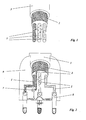
- The inventor preferred version of the item will now be described on the basis of the design drawings attached, which are:
- Fig. 1 is a schematic view of the cord, which is made up of three wires and the protective layer;
- Fig. 2 is a cross-section of a schematic view of the plug with the cord inserted;
- Fig. 3 is a schematic view of the end of the cord to be attached to the application in question and
- Fig. 4 shows a variation of Fig. 2.
-
- With reference to the drawings representing the wiring system, 1 indicates the wires that make up the cord, 2 indicates the protective layer and 3 indicates the final or outside insulation.
- The
conductor 2, which has been called a "protective layer", is connected to the earth wire at the users' end. Although there is no earth wire inside the application being used, by inserting the cord concerning the invention (which does contain an earth wire), this wire will be connected to the protective layer, which creates the protection by deviating the current towards the plug. - Fig. 2 shows the
plug 6, which has a small light 7 (for example a neon light) connected to theprotective layer 2 and aresistor 8, which is connected to the internal phase and the neutral plug. This allows continuous indication of the correct functioning of the protective system. - Fig. 3 shows how to make the connection if there is no earth wire inside the application in question. In this drawing, 1 indicates the cord wires, 2 indicates the protective layer, 3 indicates the external insulation, 4 indicates the connection between the earth wire and the protective layer and 5 indicates the terminals on the application being used.
- If there is an earth terminal within the application being used, the connection 4, shown in Fig. 3, (connection between the protective layer and the earth wire) will be part of the earth terminal within the application in question.
Claims (5)
- Electrical conductor characterised by the fact that it is made up of internal wires (1) surrounded by a protective layer (2) before the external insulation (3).
- Electrical conductor as in the claim 1, characterised by the fact that it is composed of three wires, including the earth wire.
- Electrical conductor as in the claim 1, characterised by the fact that the protective layer (2) is connected to the earth wire of the electrical conductor inside the plug.
- Electrical conductor as in the preceding claims, characterised by the fact that the protection system is constantly monitored by a light (7), for example a neon light, connected to the protective layer (2) and a resistor (8), said resistor being connected to the internal phase and the neutral plug.
- Electrical conductor as in the preceding claims, characterised by the fact that it can be used in any situation requiring a specific use of electrical items such as hairdriers or other household electrical items used daily, such as centrifuges, food mixers, etc.
Applications Claiming Priority (2)
| Application Number | Priority Date | Filing Date | Title |
|---|---|---|---|
| ITRM20030110 | 2003-03-11 | ||
| IT000110A ITRM20030110A1 (en) | 2003-03-11 | 2003-03-11 | IMPROVEMENT IN ELECTRIC CONDUCTORS FOR SMALL USERS. |
Publications (1)
| Publication Number | Publication Date |
|---|---|
| EP1457997A1 true EP1457997A1 (en) | 2004-09-15 |
Family
ID=29765703
Family Applications (1)
| Application Number | Title | Priority Date | Filing Date |
|---|---|---|---|
| EP04425156A Withdrawn EP1457997A1 (en) | 2003-03-11 | 2004-03-09 | Improvement in electrical conductors in items for everyday use |
Country Status (2)
| Country | Link |
|---|---|
| EP (1) | EP1457997A1 (en) |
| IT (1) | ITRM20030110A1 (en) |
Cited By (3)
| Publication number | Priority date | Publication date | Assignee | Title |
|---|---|---|---|---|
| WO2006063914A1 (en) * | 2004-12-13 | 2006-06-22 | Robert Bosch Gmbh | Diagnostic system for monitoring a plug-in connection |
| FR2899030A1 (en) * | 2006-03-24 | 2007-09-28 | Rayponse Sarl | Electrical installation for use in e.g. dwelling premise, has outer casing including inner conducting layer charged of conducting particles, and connector including socket that is connected to ground, which is connected to conducting layer |
| CN103457108A (en) * | 2013-09-03 | 2013-12-18 | 李秋山 | Intelligent plug-in connector with corrected polarities |
Citations (3)
| Publication number | Priority date | Publication date | Assignee | Title |
|---|---|---|---|---|
| US3890030A (en) * | 1973-09-27 | 1975-06-17 | Johnny B Mcdaniel | Lack of ground indicator |
| DE3338232A1 (en) * | 1983-08-10 | 1985-03-28 | Gebatec Geräte- und Bauelemente-Technik GmbH, 3554 Gladenbach | Electrical cable |
| JPH11111391A (en) * | 1997-10-01 | 1999-04-23 | Canon Inc | Shielded cable with connector, electronic equipment, connector member and connector |
-
2003
- 2003-03-11 IT IT000110A patent/ITRM20030110A1/en unknown
-
2004
- 2004-03-09 EP EP04425156A patent/EP1457997A1/en not_active Withdrawn
Patent Citations (3)
| Publication number | Priority date | Publication date | Assignee | Title |
|---|---|---|---|---|
| US3890030A (en) * | 1973-09-27 | 1975-06-17 | Johnny B Mcdaniel | Lack of ground indicator |
| DE3338232A1 (en) * | 1983-08-10 | 1985-03-28 | Gebatec Geräte- und Bauelemente-Technik GmbH, 3554 Gladenbach | Electrical cable |
| JPH11111391A (en) * | 1997-10-01 | 1999-04-23 | Canon Inc | Shielded cable with connector, electronic equipment, connector member and connector |
Non-Patent Citations (1)
| Title |
|---|
| PATENT ABSTRACTS OF JAPAN vol. 1999, no. 09 30 July 1999 (1999-07-30) * |
Cited By (6)
| Publication number | Priority date | Publication date | Assignee | Title |
|---|---|---|---|---|
| WO2006063914A1 (en) * | 2004-12-13 | 2006-06-22 | Robert Bosch Gmbh | Diagnostic system for monitoring a plug-in connection |
| JP2008523369A (en) * | 2004-12-13 | 2008-07-03 | ローベルト ボツシユ ゲゼルシヤフト ミツト ベシユレンクテル ハフツング | Diagnostic system for monitoring plug connections |
| FR2899030A1 (en) * | 2006-03-24 | 2007-09-28 | Rayponse Sarl | Electrical installation for use in e.g. dwelling premise, has outer casing including inner conducting layer charged of conducting particles, and connector including socket that is connected to ground, which is connected to conducting layer |
| WO2007122310A1 (en) * | 2006-03-24 | 2007-11-01 | Rayponse | Electrical installation comprising an electrical cable providing protection against the electrical field |
| CN103457108A (en) * | 2013-09-03 | 2013-12-18 | 李秋山 | Intelligent plug-in connector with corrected polarities |
| CN103457108B (en) * | 2013-09-03 | 2018-07-13 | 普罗万电子科技(厦门)有限公司 | The intelligent connector of polarity correction |
Also Published As
| Publication number | Publication date |
|---|---|
| ITRM20030110A0 (en) | 2003-03-11 |
| ITRM20030110A1 (en) | 2004-09-12 |
Similar Documents
| Publication | Publication Date | Title |
|---|---|---|
| US5642248A (en) | Electrical extension cord with built-in safety protection | |
| US7813091B2 (en) | Leakage current detector interrupter with continuous duty relay | |
| US7887363B1 (en) | Protective electrical wiring device and system | |
| US4649457A (en) | Surge protection device | |
| CN106936030B (en) | For the ground terminal of electronic equipment | |
| US10271440B2 (en) | Multi-chamber GFCI housing apparatus | |
| US20180220541A1 (en) | Multi-Chamber GFCI Housing Apparatus | |
| CA2243466A1 (en) | Plug socket | |
| FI980789A0 (en) | Foerfarande Foer avstaengning av elektricitetsmatningen vid fara och motsvarande saekerhetsarrangemang | |
| CA2563587C (en) | Electrical receptacle | |
| CN202206074U (en) | Protective electrical wiring device | |
| US20060198067A1 (en) | Extension cord having open neutral during fault detection trip | |
| KR100425423B1 (en) | A plug for confirming the ground which absorbs and removes electric waves | |
| KR102771583B1 (en) | Assembly for power outlet with leakage current recovery function | |
| US20130284490A1 (en) | Electrical wiring system and method | |
| US7944364B1 (en) | Protected power cord | |
| AU2016302166B2 (en) | Pre-filled splice connector | |
| US20060170428A1 (en) | Electrical safety cord | |
| EP1113476A3 (en) | Electronic trip unit with a rating plug for circuit breakers, which has a switchable motor and line protection function | |
| CN204596526U (en) | Earth leakage protective cable between a kind of electric wire | |
| GB2198299A (en) | Protected electrical supply arrangement | |
| CA1288463C (en) | Surge protection device | |
| RU2006120C1 (en) | Cable stuffing arrangement | |
| US20150325343A1 (en) | Apparatus and method for preventing accidental ground-faults in residential electical wiring systems | |
| JP3073156U (en) | Electromagnetic wave eliminator with short circuit warning function |
Legal Events
| Date | Code | Title | Description |
|---|---|---|---|
| PUAI | Public reference made under article 153(3) epc to a published international application that has entered the european phase |
Free format text: ORIGINAL CODE: 0009012 |
|
| AK | Designated contracting states |
Kind code of ref document: A1 Designated state(s): AT BE BG CH CY CZ DE DK EE ES FI FR GB GR HU IE IT LI LU MC NL PL PT RO SE SI SK TR |
|
| AX | Request for extension of the european patent |
Extension state: AL HR LT LV MK |
|
| AKX | Designation fees paid | ||
| REG | Reference to a national code |
Ref country code: DE Ref legal event code: 8566 |
|
| STAA | Information on the status of an ep patent application or granted ep patent |
Free format text: STATUS: THE APPLICATION IS DEEMED TO BE WITHDRAWN |
|
| 18D | Application deemed to be withdrawn |
Effective date: 20050316 |