EP1457910A2 - On-line system and method for processing information relating to the wear of turbine components - Google Patents
On-line system and method for processing information relating to the wear of turbine components Download PDFInfo
- Publication number
- EP1457910A2 EP1457910A2 EP04251387A EP04251387A EP1457910A2 EP 1457910 A2 EP1457910 A2 EP 1457910A2 EP 04251387 A EP04251387 A EP 04251387A EP 04251387 A EP04251387 A EP 04251387A EP 1457910 A2 EP1457910 A2 EP 1457910A2
- Authority
- EP
- European Patent Office
- Prior art keywords
- wear
- component
- user
- received
- line
- Prior art date
- Legal status (The legal status is an assumption and is not a legal conclusion. Google has not performed a legal analysis and makes no representation as to the accuracy of the status listed.)
- Withdrawn
Links
Images










Classifications
-
- G—PHYSICS
- G06—COMPUTING OR CALCULATING; COUNTING
- G06Q—INFORMATION AND COMMUNICATION TECHNOLOGY [ICT] SPECIALLY ADAPTED FOR ADMINISTRATIVE, COMMERCIAL, FINANCIAL, MANAGERIAL OR SUPERVISORY PURPOSES; SYSTEMS OR METHODS SPECIALLY ADAPTED FOR ADMINISTRATIVE, COMMERCIAL, FINANCIAL, MANAGERIAL OR SUPERVISORY PURPOSES, NOT OTHERWISE PROVIDED FOR
- G06Q10/00—Administration; Management
-
- F—MECHANICAL ENGINEERING; LIGHTING; HEATING; WEAPONS; BLASTING
- F01—MACHINES OR ENGINES IN GENERAL; ENGINE PLANTS IN GENERAL; STEAM ENGINES
- F01D—NON-POSITIVE DISPLACEMENT MACHINES OR ENGINES, e.g. STEAM TURBINES
- F01D9/00—Stators
- F01D9/02—Nozzles; Nozzle boxes; Stator blades; Guide conduits, e.g. individual nozzles
- F01D9/023—Transition ducts between combustor cans and first stage of the turbine in gas-turbine engines; their cooling or sealings
Definitions
- the respective amounts of wear of each of the components of the wear reduction kit are evaluated during inspections by field technicians.
- the field technicians may quantifiably measure the amounts of wear (in mils for example) or determine a qualitative wear range category (e.g., "high wear", “medium wear” or "light wear") of each of the wear reduction kit components.
- Data reflecting the wear measurements or wear category determinations is typically recorded by field technicians in individual spreadsheets. These spreadsheets, however, lack the capability to provide centralized access to the collection of data.
- the module associated with the selected link may enable a quantitative amount of the wear of the component to be input and received on-line.
- the module associated with the selected link may enable a qualitative wear range characterizing the amount of the wear of the component to be input and received on-line.
- the module associated with the selected link may enable a component type to be input and received on-line and display a component fleet leader corresponding to the received component type using data stored in the database.
- the module associated with the selected link may enable the displayable content to depict, on-line, an example component having a standardized level of wear.
- the module associated with the selected link may enable a search criterion to be input and received on-line and retrieve data from the database based on the received search criterion.
- the wear of the component of the at least one turbine system may comprise the wear of a material in one of following turbine components: transition piece body assembly component, bull horn cover, side seal, AFT frame creep, combustion liner assembly component, flow sleeve, cross fire tube and fuel nozzle.
- a method of identifying a component fleet leader from among a plurality of a same type of components in respective turbine systems comprises: processing an on-line user selection of a component type of the turbine system, searching a database of the on-line system based on the on-line user selection, and processing information retrieved from the database as a result of the search including identifying that component from among the plurality of components corresponding to the user-selected component type which has been in operation in its respective turbine system for the longest cumulative time as the component fleet leader.
- the selected component type may be one of the following turbine component types: transition piece body assembly component, bull horn cover, side seal, AFT frame creep, combustion liner assembly component, flow sleeve, cross fire tube and fuel nozzle.
- a method of processing information relating to wear of a component of a turbine system comprises: receiving an on-line user selection of a user-selectable link on a menu, the link being associated with a software module for generating a depiction of an example component of the turbine system having a standardized level of wear, generating displayable content depicting the example component having the standardized level of wear based on the received on-line user selection of the user-selectable link, receiving an on-line user selection of another user-selectable link on the menu, the another usable link being associated with another software module for enabling input of information relating to the wear of the component of the turbine system to be received, and generating displayable content to enable input of the information indicating the wear of the component of the turbine system to be received based on the received on-line user selection of the another user-selectable link, the information received indicating the wear of the component being relative to the example component having the standardized level of wear.
- the information received indicating the wear of the component is associated with
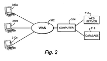
- FIG. 2 is a block diagram of an exemplary internet-based computer system for processing field inspection information such as wear-related data (hereinafter “wear data processing system”) in accordance with an exemplary embodiment of the present invention.
- the computer system includes personal computers (PCs) 310a-310c interconnected via a wide area network (WAN) 312 such as the internet.
- PCs 310a-310c are operated by users such as turbine field technicians.
- PCs 310a-310c communicate on-line via WAN 312 with web server 316.
- on-line requests from PCs 310a-310c are routed through WAN 312 to web server 316.
- PCs 310a-310c may route a request through a local area network (LAN) rather than a WAN.
- LAN local area network
- a web server application is executed on computer 314.
- Computer 314 may be, for example, a main frame computer which executes many application programs including the web server application.
- the web server application executed by computer 314 may thus communicate with web browsers executing at PCs 310a-310c using conventional HTTP protocol.
- Computer 314 also retrieves and/or stores data in database 318.
- FIG 3 is a flowchart showing exemplary initial processing operations of the wear data processing system.
- a user first accesses an internet browser, such as Netscape® or Microsoft Internet Explorer® using one of PCs 310a-310c (step 320).
- a user Using the internet browser, a user enters a wear data processing system uniform resource locator (URL) (step 322).
- This URL is received by web server 316 via WAN 312 (step 324).
- a home web page (see Fig. 5) is then generated by computer 314 and server 316 for display on the PC originally transmitting the URL (step 326).
- the home web page enables sign-on processing. In particular, the user is prompted to enter his/her login id and password.
- step 328 If the user is not an authorized user ("NO” in step 328), the server application is stopped (step 330). If, however, the user is an authorized user ("Yes” in step 328), the computer 314 and web server 316 enable access to software modules of the wear data processing system.
- Each web page generated and displayed by the wear data processing system includes a navigation pane 350 located on the left-side of the web page (see Figs. 6-20).
- the contents of the left-side navigation pane 350 essentially form a menu which includes links that allow the user to "click-on" or select the type of software module of the system he or she wishes to execute.
- Some of the web pages also include various buttons and/or input screens to allow the user to control the type of wear-related data that he or she can input, review, edit, sort, search, etc.
- the user may select another link from navigation pane 350.
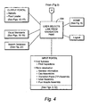
- the user may select one of the following links from navigation pane 350 (step 334) in Figure 4: "HOME” - see Figures 4 and 5, “Input Portal” - see Figures 4 and 6-12, “Output Portal” - see Figures 4 and 13-17, “Visual Standards” - see Figures 4 and 18-19, “Search Database” - see Figures 4 and 20, and “Logout” - see Figure 4.
- the user may alternatively select the same link corresponding to the web page that is being currently displayed to refresh the screen.
- a user of the wear data processing system may input inspection data such as data relating to the wear of components of a turbine system.
- a user e.g., a field technician
- data relating to the wear e.g., a quantitative measure or a qualitative wear range
- the wear of other components of the turbine system may also be entered.
- a user of the wear data processing system may also review data previously input, edit any data, statistically sort data, identify a fleet leader of a particular turbine system component, obtain a visual standard of a particular level of wear of a certain component type and/or search the database for information relating to a particular component.
- a description of displayed web pages corresponding respectively to each of the links provided in navigation pane 350 is provided below in conjunction with Figures 5-20.
- a home web page of the system will be generated and displayed.
- the home web page allows the user to enter his/her appropriate login id and password in data entry window 336.
- the system allows a guest account to be enabled through selection of "Login” button 338.
- Figure 6 illustrates an exemplary web page generated by the system resulting from a user selection of the link "Input Portal" from navigation pane 350.
- the user has the option of selecting a "Find Turbines" button 352 to search for existing turbine inspection data or to provide a turbine serial number and inspection date in window 354 to enter new data into the wear data processing system.
- This newly entered data may relate to, for example, the amount of wear on any of the components of the turbine system such as wear reduction kit components that was determined by a technician during a new field inspection.
- the user may click-on the "Continue" button 356.
- Figure 7 illustrates an exemplary web page generated by the system resulting from the selection of the "Find Turbines" button 352 in the web page illustrated in Figure 6.
- a window 358 having a drop down select box allows the user to select one of the turbines for which data has been previously entered in the wear data processing system.
- a user may select a specific turbine serial number ("295816 (7E Standard)" in the example illustrated in Figure 7) using the drop down select box in window 358 and then click on the "Find Inspections" button 360.
- Figure 8 illustrates an exemplary web page generated by the system resulting from the input of a particular turbine serial number in window 358 and selection of the "Find Inspections" button 360 in the web page illustrated in Figure 7.
- an inspection report for the particular turbine identified in the web page of Figure 7 is displayed on the user's PC.
- the inspection report includes(from left to right in the inspection report) the inspection id formed by a turbine serial number and month and year of inspection, the inspection date, a name of a contact person, a name of the person who created the information relating to that inspection, and the creation date.
- a user may click on any particular inspection to view and/or edit its details. For example, the first row 362 having inspection id "295816 10_96" can be selected by the user to view and/or edit the details of this particular inspection.
- Figure 9 is an exemplary web page generated by the system resulting from the selection of one of the rows of the inspection report illustrated in the web page of Figure 8.
- the user has selected the first row 362 of the inspection report having inspection id "295816 10_96".
- the web page illustrated in Figure 9 provides a list of can assemblies for the selected turbine (i.e., the turbine associated with the selected row of the inspection report).
- the list provided in the web page of Figure 9 indicates ten cans having respective can numbers 1-10.
- Each of the cans has a transition piece (TP) assembly, a liner assembly and a fuel nozzle assembly as indicated by the columns (from left to right) on the web page.
- TP transition piece
- a user may click on one of the assemblies of one of the cans in order to view and/or edit detailed information for that particular can assembly of the selected turbine. For example, a user may select "TP Assembly” 364 or "Liner Assembly” 366 or "Fuel Nozzle Assembly” 368 of can number 1 from the first row of data presented in the web page of Figure 9.
- Figure 10 is an exemplary web page resulting from the user's selection of the term "TP Assembly" 364 from the web page illustrated in Figure 9.
- the user may view and/or edit inspection data such as wear data of turbine system components which relate specifically to an inspection of the transition piece (TP) assembly of can number 1 of the turbine having serial no. 295816. All of the entered data may be stored in database 318. After the data is stored, centralized access to this data is available to other users via computer 314 and server 316.
- inspection data such as wear data of turbine system components which relate specifically to an inspection of the transition piece (TP) assembly of can number 1 of the turbine having serial no. 295816. All of the entered data may be stored in database 318. After the data is stored, centralized access to this data is available to other users via computer 314 and server 316.
- the user may view and/or edit the "Quantitative Wear" of various transition piece assembly components of can number 1 of the turbine system. Specifically, a user may view and/or edit the amount of "Quantitative Wear” of one or more of the following components of transition piece body assembly: H block, forward (FWD) inner portion of the transition piece body, outer floating seal, inner floating seal, aft frame in mils, and thermal barrier coating(TBC) in sq. ins.
- the TBC may be a thermal protective ceramic coating applied to high temperature components for reducing thermal stress.
- a user may also view and/or edit the amount of "Quantitative Wear” in mils of the following additional transition piece assembly components: Bull Horn Cover, Side Seal, Aft Frame Creep (Left), Aft Frame Creep (Center) and Aft Frame Creep (Right).
- Aft refers to the rear end and "Aft Frame Creep” refers to deformation of the rear end of the transition piece via a mechanical strain process referred to as creep.
- the amount of "Quantitative Wear” may be measured by a field technician through the use of, for example, a micrometer.
- a field engineer During an inspection, a field engineer must typically examine the wear of many components of the turbine system. The field engineer may thus not have the time to quantitatively measure the amount of wear for each of these turbine system components. Rather than determine a quantitative measure of the wear of each of these components, a field technician may determine the "Wear Range” ("light” amount of wear, "medium” amount of wear or “heavy” amount of wear) of each of the turbine system components. The wear range of components of the transition piece assembly may be reviewed and/or edited by a user (e.g., field engineer) in column 372.
- a user e.g., field engineer
- the "H Block”, “Outer Floating Seal” and “Inner Floating Seal” of can number 1 of the TP body assembly were entered as having a "light” amount of wear during the 10/1/1996 inspection of turbine no. 295816.
- the wear range of the "Side Seal” was entered as having a medium amount of wear as can be seen in the lower portion of column 372.
- Each of the "Wear Ranges” of the components of the transition piece assembly may be viewed and revised using the appropriate drop down box in "Wear Range” column 372.
- a field engineer may obtain a picture (e.g., take a digital photograph) of a particular component of the turbine system. For example, the field engineer may photograph any portion of the "TP Body Assembly", “Bull Horn Cover”, “Side Seal” and "Aft Frame Creep". This picture may be uploaded through the selection of column 376 in the web page illustrated in Figure 10. After the picture has been uploaded, a user may select an appropriate row in column 376 to view the picture of that particular component.
- a serial number of a particular component of the TP body assembly may be entered and stored in database 318.
- a user may review and/or edit the serial number through appropriate data entry in column 378.
- Figure 11 discloses a web page resulting from the selection of "Liner Assembly (can 1)" button 382 in the web page illustrated in Figure 10 or the selection of the term “Liner Assembly” 366 in the web page illustrated in Figure 9.
- the web page illustrated in Figure 11 includes the same columns as columns 370-378 illustrated in the web page of Figure 10.
- a user may thus enter the quantitative amount of wear or a qualitative wear range characterizing the amount of wear in the columns labeled "Quantitative Wear” and "Wear Range” for the following components of the combustion liner of can number 1 of the turbine having serial no. 295816: "XFT Collar (Left)", “XFT Collar (Right)", “Liner Collar", “Liner Stops” and "Hula Seal”.
- the user may also view and/or edit the quantitative amount of wear or qualitative wear range for the following turbine system components: “Flow Sleeve Stop Maximum”, “X-Fire Tube (Right)” and “X-Fire Tube (Left)”.
- a picture of the cross-fire tube (XFT or X-Fire tube) collar, cross-fire tube and liner stops A-F is provided in window portion 389 to aid the user to identify the appropriate component part.
- a user may view and/or edit whether the "Liner", “Flow Sleeve Stop Maximum”, “X-Fire Tube (Right)” and/or “X-Fire Tube (Left)” have been replaced.
- a picture e.g., digital photograph
- a serial number of the combustion liner may be viewed and/or edited.
- the web page illustrated in Figure 11 may include "Can Assemblies”, “TP Assembly (can 1)”, “Fuel Nozzle Assembly (Can 1)” and “Next Can” buttons to allow the user to efficiently select the next web page for viewing.
- Figure 12 illustrates the web page resulting from the selection of the term "Fuel Nozzle Assembly” 368 in the web page illustrated in Figure 9 or the "Fuel Nozzle Assembly (Can 1)" button 384 in the web page illustrated in Figure 10 (or Figure 11).
- a user may view and/or edit inspection data relating to the "Fuel Nozzle Assembly” of any can of the turbine system.
- the columns "Quantitative Wear”, “Wear Range”, “Replaced”, “Picture (optional)” and “Serial Number” are similar to columns 370-378 illustrated in the web page of Figure 10.
- a user may view and/or edit the amount of quantitative wear of the primary fuel nozzle or view and/or edit a qualitative wear range characterizing the amount of wear of the primary fuel nozzle in the "Quantitative Wear” and “Wear Range” columns, respectively.
- a user may also indicate whether the primary fuel nozzle has been replaced through the appropriate selection in the "Replaced” column.
- a picture may be viewed or uploaded through selection of the "Picture (optional)" column.
- a serial number of the primary fuel nozzle may also be viewed and/or edited in the "Serial Number" column. Comments regarding the fuel nozzle assembly may be entered in window 390. For example, any comments regarding the wear of the fuel nozzle may be viewed and/or edited in window 390. Rather then allowing a user to edit data in the web page illustrated in Figure 12, access can be limited to viewing only.
- new inspection data for a particular turbine can be entered by providing a turbine serial number and inspection date in window 354 and selecting the "Continue" button 356.
- web pages such as those illustrated in Figures 9-12 will be displayed to enable the user to input data relating to the inspection.
- These web pages prompt users to enter inspection data in a consistent manner. For example, different users are prompted to newly enter, data relating to the "Quantitative Wear” or "Wear Range" of the transitional piece assembly, combustion liner and/or fuel nozzle assembly in a consistent manner.
- This data will be stored in database 318 and processed by the wear data processing system. The data can be immediately viewed by other users having access to the wear data processing system.
- Figure 13 illustrates an exemplary web page resulting from the selection of the link "Output Portal" in navigation pane 350.
- a user is prompted to select either the "Statistic” button 400 or the “Fleet Leader” button 402.
- the "Statistic” button 400 a user may perform a statistical sorting of existing inspection data including wear-related data.
- the "Fleet Leader” button 402 a user may view fleet leader units of the various types of turbine components.
- Figure 14 is an exemplary web page resulting from the selection of the "Statistic" button 400.
- search criteria as attributes for data sorting. Wild cards such as * and ? may be used by the user where needed.
- the user may enter one or more of the following as possible search criteria: the "Type" of turbine system component such as "H Block (TP)” as indicated in Figure 14, "Turbine Serial Number”, “Turbine Type” such as “7E” as illustrated in Figure 14, "Combustor Type” such as “Standard”, “Can Number” and “Liner Stop Location” (for liner stops only).
- search button 404 After entering in the appropriate search criteria, a user may click on search button 404 to view data retrieved and sorted on the basis of the search criteria. If the user makes a mistake in one or more of his/her search criteria entries, he/she may click on the "Reset" button 405 to clear all of the search criteria fields.
- Figure 15 is an exemplary web page resulting from the input search criteria and selection of search button 404 in the web page illustrated in Figure 14.
- a user may thus efficiently view inspection data that has been sorted based on the search criteria input in the web page illustrated in Figure 14.
- one column of information for the selected component is "Wear” (third column from the right).
- a user may select "WearPlot" button 410 to view a graphical plot of the wear data.
- Figure 16 is an exemplary web page generated by the system resulting from the selection of the "Fleet Leader" button 402 in the web page illustrated in Figure 13.
- the user may view an identified fleet leader through appropriate input of search criteria.
- a fleet leader of a particular turbine component is that component from amongst the same type of components installed at different turbines which has the most time in operation.
- identifying the fleet leader a user may determine which component of the various turbine installations is most likely to be in need of being replaced.
- information regarding how long a particular component has lasted in operation may be used in marketing information.
- a user may enter in the type of fleet leader such as "Fleet Leader by Hours", a particular turbine type such as “7E” and/or a certain combustor type such as "Standard”.
- Search button 412 may then be selected by the user to enable the fleet leader to be identified based on the input search criteria.
- the search criteria may be cleared through selection of reset button 414.
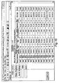
- Figure 17 is an exemplary web page illustrating the fleet leaders identified based on the search criteria entered in the web page illustrated in Figure 16.
- the identification of the fleet leaders involves a ranking of a particular type of turbine system component within various turbines.
- TP transition piece
- the transition piece installed in the turbine having number 282508 has the longest duration of cumulative operation.
- the transition piece installed in turbine having number 295816 has the second longest duration of cumulative operation as measured by the number of interval fired hours.
- the liner assembly component of turbine type "7E” and combustor “Standard” that has the highest number of interval fire hours (i.e., the longest cumulative operation time as measured by interval fire hours) is the liner assembly installed in turbine number 295816.
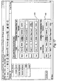
- Figure 18 is an exemplary web page of the wear monitoring system resulting from the selection of the link "Visual Standards" from navigation pane 350.
- a user may view and/or edit the "Wear Range” (e.g., "light” wear, “medium” wear or “heavy” wear).
- a field technician makes a qualitative determination of the amount of wear of a particular turbine system component. For example, the field technician may make a qualitative decision on the amount of wear on the following turbine system components: bull horn cover, hula seal, inner floating seal, liner collar, liner stop, fuel nozzle, side seal, XF tube male, XFT left collar, and XFT right collar.
- a particular turbine system component type may be selected in the web page illustrated in Figure 18 to obtain a visual standard. That is, a particular turbine system component type may be selected to view a picture (e.g., digital photograph) of a component having a light amount, medium amount and heavy amount of wear by selecting the appropriate icon in column 440.
- Figure 19 illustrates picture 446 forming a visual standard for a liner stop of the turbine system having a "heavy" amount of wear. Picture 446 may be displayed upon the selection of icon 440a.
- Other visual standards for other component types may be obtained through selection of the icon in column 440 corresponding to the appropriate row.
- detailed written notes describing the particular picture forming the visual standard may be obtained by selection of the icon in column 442 corresponding to the appropriate row.
- Figure 20 is an exemplary web page resulting from the selection of the link "Search Database” in navigation pane 350.
- information stored in database 318 can be searched through input of the appropriate search criteria. Wild cards such as * and ? may be used by the user where needed.
- the user may input one or more of the following fields as search criteria: "Type”, “Name”, “Revision”, “Owner”, “Vault”, “State”, “Created Between”, “Description”, “Attachment Preference” and “Find Limit”.
- the “Type” field allows the user to search for a particular type of turbine system component.
- the "Name” field allows the user to enter in a specific inspection site.
- the "Revision” field allows the user to search between different edits of the inspection data relating to the same inspection.
- the “Owner” field allows the user to use the person who inputs the data (i.e., the field data engineer) as a search criteria.
- the "Vault” field allows the user to search for data among various vaults or servers.
- the "State” field allows the user to search for the location state (e.g., New York) where the data was entered.
- the "Created Between” field allows the user to search for data that is created during a certain time period.
- the “Description” field allows the user to search from among any additional information that may be specific to a particular inspection.
- the field “Attachment Preference” allows the user to restrict the attachments that the user may want to view.
- the “Find Limit” field allows the user to restrict the number of matching hits that the search criteria will find. The user may then select the "Search” button in Figure 20 to enable the search or the "Reset” button to clear
Landscapes
- Engineering & Computer Science (AREA)
- Business, Economics & Management (AREA)
- Operations Research (AREA)
- Quality & Reliability (AREA)
- Economics (AREA)
- Entrepreneurship & Innovation (AREA)
- Human Resources & Organizations (AREA)
- Marketing (AREA)
- Mechanical Engineering (AREA)
- General Engineering & Computer Science (AREA)
- Strategic Management (AREA)
- Tourism & Hospitality (AREA)
- Physics & Mathematics (AREA)
- General Business, Economics & Management (AREA)
- General Physics & Mathematics (AREA)
- Theoretical Computer Science (AREA)
- Control Of Turbines (AREA)
- Management, Administration, Business Operations System, And Electronic Commerce (AREA)
Abstract
Description
Claims (10)
- A method of processing information relating to wear of a component of a turbine system, the method comprising:receiving an on-line user selection of a user-selectable link on a menu (350), the link being associated with a software module for generating a depiction of an example component of the turbine system having a standardized level of wear (446);generating displayable content depicting the example component having the standardized level of wear based on the received on-line user selection of the user-selectable link;receiving an on-line user selection of another user-selectable link on the menu, the another usable link being associated with another software module for enabling input of information relating to the wear of the component of the turbine system to be received; andgenerating displayable content to enable input of the information indicating the wear of the component of the turbine system to be received based on the received on-line user selection of the another user-selectable link, the information received indicating the wear of the component being relative to the example component having the standardized level of wear.
- A method of claim 1, wherein the information received indicating the wear of the component is a quantitative measure of the amount of the wear.
- A method of claim 1, wherein the information received indicating the wear of the component is a qualitative wear range characterizing the amount of the wear.
- A system for processing wear related information, the system comprising:a database (318) for storing data relating to wear of a component of at least one turbine system; anda computer system (314, 316) executing a software application including a plurality of software modules to (i) generate a displayable menu (350) containing a plurality of user-selectable links respectively associated with the software modules, and (ii) process a received on-line selection of one of the user-selectable links to enable the associated software module to generate displayable content including information relating to the wear of the component of the turbine system.
- A system of claim 4, wherein the module associated with the selected link enables a quantitative amount (370) of the wear of the component to be input and received on-line.
- A system of claim 4, wherein the module associated with the selected link enables a qualitative wear range (372) characterizing the amount of the wear of the component to be input and received on-line.
- A system of claim 4, 5 or 6, wherein the module associated with the selected link enables a component type to be input and received on-line and displays a component fleet leader (420, 430) corresponding to the received component type using data stored in the database (378).
- A system of any one of claims 4 to 7, wherein the module associated with the selected link enables the displayable content to depict, on-line, an example component having a standardized level of wear (446).
- A system of any one of claims 4 to 8, wherein the module associated with the selected link enables a search criterion to be input and received on-line and retrieves data from the database based on the received search criterion.
- A system of any one of claims 4 to 9, wherein the wear of the component of the at least one turbine system comprises the wear of a material in one of following turbine components: transition piece body assembly components, bull horn cover, side seal, AFT frame creep, combustion liner assembly components, flow sleeve, cross fire tube and fuel nozzle.
Applications Claiming Priority (2)
| Application Number | Priority Date | Filing Date | Title |
|---|---|---|---|
| US249015 | 2003-03-10 | ||
| US10/249,015 US7149632B1 (en) | 2003-03-10 | 2003-03-10 | On-line system and method for processing information relating to the wear of turbine components |
Publications (2)
| Publication Number | Publication Date |
|---|---|
| EP1457910A2 true EP1457910A2 (en) | 2004-09-15 |
| EP1457910A3 EP1457910A3 (en) | 2007-11-28 |
Family
ID=32770061
Family Applications (1)
| Application Number | Title | Priority Date | Filing Date |
|---|---|---|---|
| EP04251387A Withdrawn EP1457910A3 (en) | 2003-03-10 | 2004-03-10 | On-line system and method for processing information relating to the wear of turbine components |
Country Status (3)
| Country | Link |
|---|---|
| US (1) | US7149632B1 (en) |
| EP (1) | EP1457910A3 (en) |
| JP (1) | JP2004270702A (en) |
Cited By (1)
| Publication number | Priority date | Publication date | Assignee | Title |
|---|---|---|---|---|
| US9970325B2 (en) | 2015-04-30 | 2018-05-15 | General Electric Company | Jacking assembly for rotor |
Families Citing this family (17)
| Publication number | Priority date | Publication date | Assignee | Title |
|---|---|---|---|---|
| ITMI20031669A1 (en) * | 2003-08-26 | 2005-02-27 | Nuovo Pignone Spa | MONITORING SYSTEM FOR THE COMPONENTS OF A GAS TURBINE. |
| US7844385B2 (en) * | 2004-01-28 | 2010-11-30 | United Technologies Corporation | Microserver engine control card |
| US8392418B2 (en) * | 2009-06-25 | 2013-03-05 | University Of Tennessee Research Foundation | Method and apparatus for predicting object properties and events using similarity-based information retrieval and model |
| US8396870B2 (en) * | 2009-06-25 | 2013-03-12 | University Of Tennessee Research Foundation | Method and apparatus for predicting object properties and events using similarity-based information retrieval and modeling |
| GB2477324A (en) * | 2010-02-01 | 2011-08-03 | Rolls Royce Plc | Device monitoring |
| WO2012054867A1 (en) * | 2010-10-21 | 2012-04-26 | Vibrant Corporation | Utilizing resonance inspection of in-service parts |
| US8826667B2 (en) | 2011-05-24 | 2014-09-09 | General Electric Company | System and method for flow control in gas turbine engine |
| US8601820B2 (en) | 2011-06-06 | 2013-12-10 | General Electric Company | Integrated late lean injection on a combustion liner and late lean injection sleeve assembly |
| US9010120B2 (en) | 2011-08-05 | 2015-04-21 | General Electric Company | Assemblies and apparatus related to integrating late lean injection into combustion turbine engines |
| US8919137B2 (en) | 2011-08-05 | 2014-12-30 | General Electric Company | Assemblies and apparatus related to integrating late lean injection into combustion turbine engines |
| US9140455B2 (en) | 2012-01-04 | 2015-09-22 | General Electric Company | Flowsleeve of a turbomachine component |
| FR3022065B1 (en) * | 2014-06-04 | 2017-10-13 | European Aeronautic Defence & Space Co Eads France | METHOD FOR GENERATING AN ENRICHED DIGITAL MODEL |
| US20170038275A1 (en) * | 2015-08-04 | 2017-02-09 | Solar Turbines Incorporated | Monitoring system for turbomachinery |
| US11377970B2 (en) | 2018-11-02 | 2022-07-05 | Chromalloy Gas Turbine Llc | System and method for providing compressed air to a gas turbine combustor |
| US11248797B2 (en) * | 2018-11-02 | 2022-02-15 | Chromalloy Gas Turbine Llc | Axial stop configuration for a combustion liner |
| US11156112B2 (en) * | 2018-11-02 | 2021-10-26 | Chromalloy Gas Turbine Llc | Method and apparatus for mounting a transition duct in a gas turbine engine |
| US12085283B2 (en) * | 2021-06-07 | 2024-09-10 | General Electric Company | Combustor for a gas turbine engine |
Family Cites Families (21)
| Publication number | Priority date | Publication date | Assignee | Title |
|---|---|---|---|---|
| US5162659A (en) * | 1991-03-06 | 1992-11-10 | Northwest Airlines, Inc. | Method and apparatus for noncontact inspection of engine blades |
| US5528496A (en) * | 1993-04-29 | 1996-06-18 | Hunter Engineering Company | Vehicle alignment system and method incorporating digital photograph database of vehicles |
| US5442549A (en) * | 1993-06-08 | 1995-08-15 | Hunter Engineering Company | Diagnostic vehicle alignment system |
| US5749218A (en) * | 1993-12-17 | 1998-05-12 | General Electric Co. | Wear reduction kit for gas turbine combustors |
| US6041287A (en) * | 1996-11-07 | 2000-03-21 | Reliance Electric Industrial Company | System architecture for on-line machine diagnostics |
| US6014287A (en) * | 1998-05-15 | 2000-01-11 | Iomega Corporation | Speed plate |
| US6499114B1 (en) * | 1999-02-17 | 2002-12-24 | General Electric Company | Remote diagnostic system and method collecting sensor data according to two storage techniques |
| US6173159B1 (en) * | 1999-06-25 | 2001-01-09 | Harris Corporation | Wireless spread spectrum ground link-based aircraft data communication system for updating flight management files |
| US6636813B1 (en) * | 1999-09-27 | 2003-10-21 | Hitchi, Ltd. | Service life management system for high-temperature part of gas turbine |
| US6668272B1 (en) * | 1999-11-05 | 2003-12-23 | General Electric Company | Internet-based process optimization system and method |
| US6408259B1 (en) * | 2000-02-01 | 2002-06-18 | General Electric Company | Alert generation for trend performance analysis |
| US6421571B1 (en) * | 2000-02-29 | 2002-07-16 | Bently Nevada Corporation | Industrial plant asset management system: apparatus and method |
| US6556956B1 (en) * | 2000-06-30 | 2003-04-29 | General Electric Company | Data acquisition unit for remote monitoring system and method for remote monitoring |
| US6378371B1 (en) * | 2000-09-29 | 2002-04-30 | General Electric Company | Apparatus and methods for determining natural frequencies of brush seals |
| US6343251B1 (en) * | 2000-10-20 | 2002-01-29 | General Electric Company | Method and system for monitoring the operation of and predicting part life consumption for turbomachinery |
| US6438484B1 (en) * | 2001-05-23 | 2002-08-20 | General Electric Company | Method and apparatus for detecting and compensating for compressor surge in a gas turbine using remote monitoring and diagnostics |
| US6542856B2 (en) * | 2001-06-15 | 2003-04-01 | General Electric Company | System and method for monitoring gas turbine plants |
| US6644917B2 (en) * | 2001-08-14 | 2003-11-11 | General Electric Company | Smart coating system with chemical taggants for coating condition assessment |
| US6760689B2 (en) * | 2002-01-04 | 2004-07-06 | General Electric Co. | System and method for processing data obtained from turbine operations |
| US6839660B2 (en) * | 2002-04-22 | 2005-01-04 | Csi Technology, Inc. | On-line rotating equipment monitoring device |
| US6880341B2 (en) * | 2002-12-18 | 2005-04-19 | Pratt & Whitney Canada Corp. | Low cost combustor floating collar with improved sealing and damping |
-
2003
- 2003-03-10 US US10/249,015 patent/US7149632B1/en not_active Expired - Fee Related
-
2004
- 2004-03-09 JP JP2004064999A patent/JP2004270702A/en not_active Withdrawn
- 2004-03-10 EP EP04251387A patent/EP1457910A3/en not_active Withdrawn
Cited By (2)
| Publication number | Priority date | Publication date | Assignee | Title |
|---|---|---|---|---|
| US9970325B2 (en) | 2015-04-30 | 2018-05-15 | General Electric Company | Jacking assembly for rotor |
| US10344625B2 (en) | 2015-04-30 | 2019-07-09 | General Electric Company | Jacking assembly for rotor |
Also Published As
| Publication number | Publication date |
|---|---|
| US20060271311A1 (en) | 2006-11-30 |
| JP2004270702A (en) | 2004-09-30 |
| US7149632B1 (en) | 2006-12-12 |
| EP1457910A3 (en) | 2007-11-28 |
Similar Documents
| Publication | Publication Date | Title |
|---|---|---|
| US7149632B1 (en) | On-line system and method for processing information relating to the wear of turbine components | |
| JP3625418B2 (en) | Maintenance information management system and maintenance plan providing method | |
| JP4295952B2 (en) | Method and system for providing remote access | |
| US6853975B1 (en) | Method of rating employee performance | |
| US7051046B2 (en) | System for managing environmental audit information | |
| US6704015B1 (en) | Methods and apparatus for providing a quality control management system | |
| US8095394B2 (en) | Rich claim reporting system | |
| US20080082568A1 (en) | System and method for managing and utilizing information | |
| US20040103112A1 (en) | Computer based method and apparatus for mining and displaying patent data | |
| US20050021521A1 (en) | Embedding Internet message board display links | |
| US20060136461A1 (en) | Method and system for data quality management | |
| US20040138792A1 (en) | System and method for efficiently capturing and reporting maintenance, repair, and overhaul data | |
| US20100005401A1 (en) | Graphical user interfaces | |
| EP1586055A2 (en) | Knowledge-management systems for law firms | |
| FR2814564A1 (en) | METHOD AND APPARATUS FOR CLASSIFYING EQUIPMENT IN AN ASSET MANAGEMENT DATABASE | |
| NZ530061A (en) | Improved search engine | |
| JP2003228676A (en) | Payment-type placement search system and method enabling search list management by advertiser using grouping | |
| JP2002149217A (en) | Method for providing management / maintenance parts and system for providing the same | |
| WO2004074958A2 (en) | Portal for global portfolio management system method & apparatus | |
| US8402082B2 (en) | Maintenance information management system, management apparatus, and maintenance information management method | |
| US20050086248A1 (en) | Issue tracking | |
| US7984047B2 (en) | System for extracting relevant data from an intellectual property database | |
| US20060069690A1 (en) | Electronic file system graphical user interface | |
| US20020016797A1 (en) | Network based interviewing and processing system | |
| EP1304606B1 (en) | Systems and methods for coordinating QA events |
Legal Events
| Date | Code | Title | Description |
|---|---|---|---|
| PUAI | Public reference made under article 153(3) epc to a published international application that has entered the european phase |
Free format text: ORIGINAL CODE: 0009012 |
|
| AK | Designated contracting states |
Kind code of ref document: A2 Designated state(s): AT BE BG CH CY CZ DE DK EE ES FI FR GB GR HU IE IT LI LU MC NL PL PT RO SE SI SK TR |
|
| AX | Request for extension of the european patent |
Extension state: AL HR LT LV MK |
|
| RIN1 | Information on inventor provided before grant (corrected) |
Inventor name: ELLIOTT, RICHARD ANTHONY Inventor name: SARSHAR, HAMID REZA Inventor name: XIA, HONG Inventor name: GAO, DONGMING |
|
| PUAL | Search report despatched |
Free format text: ORIGINAL CODE: 0009013 |
|
| AK | Designated contracting states |
Kind code of ref document: A3 Designated state(s): AT BE BG CH CY CZ DE DK EE ES FI FR GB GR HU IE IT LI LU MC NL PL PT RO SE SI SK TR |
|
| AX | Request for extension of the european patent |
Extension state: AL LT LV MK |
|
| 17P | Request for examination filed |
Effective date: 20080528 |
|
| AKX | Designation fees paid |
Designated state(s): CH DE GB LI |
|
| 17Q | First examination report despatched |
Effective date: 20080723 |
|
| STAA | Information on the status of an ep patent application or granted ep patent |
Free format text: STATUS: THE APPLICATION IS DEEMED TO BE WITHDRAWN |
|
| 18D | Application deemed to be withdrawn |
Effective date: 20090203 |