EP1457814A2 - QPM wavelength converter device, its manufacturing method, and medical laser apparatus using it - Google Patents
QPM wavelength converter device, its manufacturing method, and medical laser apparatus using it Download PDFInfo
- Publication number
- EP1457814A2 EP1457814A2 EP04005582A EP04005582A EP1457814A2 EP 1457814 A2 EP1457814 A2 EP 1457814A2 EP 04005582 A EP04005582 A EP 04005582A EP 04005582 A EP04005582 A EP 04005582A EP 1457814 A2 EP1457814 A2 EP 1457814A2
- Authority
- EP
- European Patent Office
- Prior art keywords
- crystal quartz
- twins
- qpm
- wavelength converter
- stress
- Prior art date
- Legal status (The legal status is an assumption and is not a legal conclusion. Google has not performed a legal analysis and makes no representation as to the accuracy of the status listed.)
- Granted
Links
Images


Classifications
-
- G—PHYSICS
- G02—OPTICS
- G02F—OPTICAL DEVICES OR ARRANGEMENTS FOR THE CONTROL OF LIGHT BY MODIFICATION OF THE OPTICAL PROPERTIES OF THE MEDIA OF THE ELEMENTS INVOLVED THEREIN; NON-LINEAR OPTICS; FREQUENCY-CHANGING OF LIGHT; OPTICAL LOGIC ELEMENTS; OPTICAL ANALOGUE/DIGITAL CONVERTERS
- G02F1/00—Devices or arrangements for the control of the intensity, colour, phase, polarisation or direction of light arriving from an independent light source, e.g. switching, gating or modulating; Non-linear optics
- G02F1/35—Non-linear optics
- G02F1/37—Non-linear optics for second-harmonic generation
-
- G—PHYSICS
- G02—OPTICS
- G02F—OPTICAL DEVICES OR ARRANGEMENTS FOR THE CONTROL OF LIGHT BY MODIFICATION OF THE OPTICAL PROPERTIES OF THE MEDIA OF THE ELEMENTS INVOLVED THEREIN; NON-LINEAR OPTICS; FREQUENCY-CHANGING OF LIGHT; OPTICAL LOGIC ELEMENTS; OPTICAL ANALOGUE/DIGITAL CONVERTERS
- G02F1/00—Devices or arrangements for the control of the intensity, colour, phase, polarisation or direction of light arriving from an independent light source, e.g. switching, gating or modulating; Non-linear optics
- G02F1/35—Non-linear optics
- G02F1/355—Non-linear optics characterised by the materials used
- G02F1/3558—Poled materials, e.g. with periodic poling; Fabrication of domain inverted structures, e.g. for quasi-phase-matching [QPM]
-
- A—HUMAN NECESSITIES
- A61—MEDICAL OR VETERINARY SCIENCE; HYGIENE
- A61B—DIAGNOSIS; SURGERY; IDENTIFICATION
- A61B18/00—Surgical instruments, devices or methods for transferring non-mechanical forms of energy to or from the body
- A61B18/18—Surgical instruments, devices or methods for transferring non-mechanical forms of energy to or from the body by applying electromagnetic radiation, e.g. microwaves
- A61B18/20—Surgical instruments, devices or methods for transferring non-mechanical forms of energy to or from the body by applying electromagnetic radiation, e.g. microwaves using laser
Definitions
- the present invention relates to a manufacturing method for quasi phase matching (QPM) wavelength converter elements (devices) using crystal quartz as the base material (host material), a QPM wavelength converter element (device), and a medical laser apparatus using it.
- QPM quasi phase matching
- the application of the stress to the crystal quartz was previously considered to cause the twins to grow along the Z axis of the crystal quartz. For this reason, the stress application was so carried out that the angle ⁇ of the stress application relative to the Z axis of the crystal quartz is 0° ⁇ ⁇ ⁇ 60°. Further, in inducing the twins in the crystal quartz, the stress application was performed while uniformizing the temperature distribution of the crystal quartz in the vicinity of the phase transition temperature (573°C) of the crystal quartz.
- the conventional manufacturing method involves a problem that the aspect ratio in the growth of the twins is extremely low in addition to low controllability of the twins. As a result, it has been impossible to obtain practical usable QPM wavelength converter elements in bulk using the crystal quartz as the base material.
- the present invention has been made in view of the above circumstances and has an object to overcome the above problems and to improve the control of the twins in the crystal quartz, realize the growth of the twins in a high aspect ratio, and provide a manufacturing method for QPM wavelength converter elements permitting in particular for practical use wavelength conversion to the ultraviolet range, such a QPM wavelength converter element, and a medical laser apparatus using it.
- the present invention provides a manufacturing method for quasi phase matching (QPM) wavelength converter elements using crystal quartz as a base material in which twins are periodically induced, characterized by comprising: a step of periodically inducing the twins by applying a stress onto a crystal quartz substrate as the base material so that an angle ⁇ of a direction in which the stress is applied relative to a Z axis of the crystal quartz is 60° ⁇ ⁇ ⁇ 90°.
- the present invention provides a manufacturing method for quasi phase matching (QPM) wavelength converter elements using crystal quartz as a base material in which twins are periodically induced, comprising: a stress application step of periodically inducing the twins by applying a stress onto a crystal quartz substrate as the base material; and a heat treatment step of keeping a temperature between two planes of the crystal quartz substrate orthogonal to a direction in which the stress is applied at or below a phase transition temperature of the crystal quartz and creating a temperature difference between the two planes.
- QPM quasi phase matching
- the present invention provides a quasi phase matching (QPM) wavelength converter element whose base material is crystal quartz in which twins are periodically induced by applying a stress, wherein interfaces of the twins are formed in a plane containing a Y axis of the crystal quartz and the twins are formed in a direction of a Z axis of the crystal quartz periodically.
- QPM quasi phase matching
- the present invention provides a medical laser apparatus comprising a laser light source and a wavelength converter element for converting the wavelength of a laser beam from the laser light source, characterized in that the wavelength converter element is the QPM wavelength converter element mentioned above.
- Fig. 1 illustrates a schematic structure of a quasi phase matching wavelength converter element (QPM crystal quartz), which is the preferred embodiment of the invention and wavelength conversion using the QPM crystal quartz.
- QPM crystal quartz quasi phase matching wavelength converter element
- a quasi phase matching wavelength converter element (hereinafter referred to as QPM crystal quartz) 10 uses crystal quartz 11 as the base material.
- Crystal quartz has many useful features including excellent chemical stability, a high damage threshold, transparency up to the ultraviolet region of 150 nm and a lower cost than other crystals.
- the crystal quartz has advantages as a material for wavelength converter elements for the generation of ultraviolet rays.
- Twins in the crystal quartz were previously considered to grow in the direction of the Z axis of the crystal quartz when the twins in the crystal quartz were caused to grow by applying a stress.
- experimental findings by the present inventors have revealed that twins at first grow in the direction of the Y axis of the crystal quartz, followed by growth in the direction of the Z axis.
- the QPM crystal quartz 10 has the following structure.
- periodic twins 12 are induced in the direction of the Z axis of the crystal quartz 11 as the base material, resulting in the formation of a structure whose polarity is periodically inverted.
- the interfaces 12a of the twins 12 are formed in a plane containing the Y axis of the crystal quartz 11.
- the incidence vector of the fundamental wave beam 20 should preferably be, but not absolutely required to be, parallel to the direction of the Z axis of the crystal quartz 11 (substantially orthogonal to the plane of the ZY axes in Fig. 1). Since QPM is achieved in the crystal quartz 11 because the sign of its nonlinear optical constant d11 is periodically inverted, the wavelength-converted beam 21 can be taken out if the polarized beam 20a of the fundamental wave beam 20 at least has an X axis component.
- ⁇ should preferably be 0° ⁇ ⁇ ⁇ 30°.
- the interfaces 12a are supposed to contain the X axis of the crystal quartz 11 too in their planes as illustrated in Fig. 1, the interfaces 12a may as well be so formed as not to contain the X axis of the crystal quartz 11 in their planes as illustrated in Fig. 2.
- the polarized beam 20a of the fundamental wave beam 20 needs to have the X axis component.
- the angle ⁇ formed by the interfaces 12a and the X axis is at least prevented from being perpendicular.
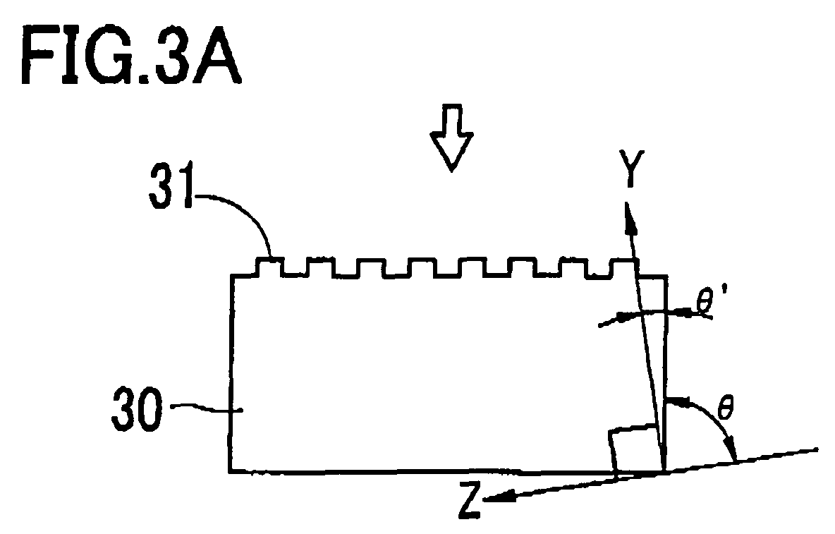
- the angle ⁇ of the direction in which the stress is applied relative to the Z axis of the crystal quartz is set to 60° ⁇ ⁇ ⁇ 90°
- the cut-out orientation ⁇ ' relative to the Y axis of the crystal quartz is set to 0° ⁇ ⁇ ⁇ 30°.
- the reason why the angle 9 of the direction in which the stress is applied relative to the Z axis of the crystal quartz is set to 60° ⁇ ⁇ ⁇ 90° is that twins have been found to grow in the direction of the Y axis of the crystal quartz.
- the angle ⁇ of the direction in which the stress is applied relative to the Z axis of the crystal quartz should be 80° ⁇ ⁇ ⁇ 88° (2° ⁇ ⁇ ' ⁇ 20°).
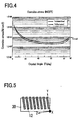
- Fig. 4 shows the result of computation of the angle-dependence of coercive stress at a temperature of 400°C.
- the curve in one-dot chain line represents the stress level at which the growth of twins begins and that in solid line is where the growth of twins is completed.
- the angle ⁇ of the direction of stress application relative to the direction of the Z axis is set to 60° ⁇ ⁇ ⁇ 90°. This is because twins have been found to grow in the direction of the Y axis of the crystal quartz.
- machining is done to form on the surface of the crystal quartz substrate 30 a stepped structure 31 having level gaps in a period of realizing the desired wavelength conversion.
- the stepped structure 31 can be formed by photolithography.
- the depth of the step is, e.g., 2 ⁇ m.
- This stepped structure 31 may be on the first heater block 40 side on which the stress would be applied to the crystal quartz substrate 30.
- the crystal quartz substrate 30, over which the stepped structure 31 is formed is sandwiched between the first heater block 40 and a second heater block 41 as shown in Fig. 3B, and a uniform uniaxial vertical stress is applied with a stress applying device 43,
- the temperature T1 of the first heater block 40 arranged on the stepped structure 31 side and the temperature T2 of the other second heater block 41 are kept at or below the phase transition temperature (573°C).
- a temperature difference ⁇ T is created between two planes orthogonal to the direction of stress application. For instance, the temperature difference ⁇ T of 175°C is created by setting T1 to 375°C and T2 to 200°C.
- the heater blocks 40 and 41 are controlled by a control device 42 to be individually variable in temperature.
- the uniform vertical stress is applied with the stress applying device 43.
- This causes anisotropic twins (twins growing in the direction of a specific axis of the crystal quartz) reflecting the level gap of the stepped structure 31 over the crystal quartz substrate 30 in the direction of the Y axis as shown in Fig. 3C, and the crystal quartz substrate 30 having periodic twins in the direction of the Z axis is obtained.
- the QPM crystal quartz 10 illustrated in Fig. 1 is obtained.
- the temperature T2 on the second heater block 41 side was gradually raised with the temperature T1 on the first heater block 40 side kept at 375°C, anisotropic twins grew until T2 reached 200°C. Then, the anisotropic twins grew longer with a rise in the temperature T2.
- T2 225°C, however, isotropic twins began to grow from the lower temperature side (the second heater block 41 side). Therefore, no twins are induced from the other side of the stepped structure 31, and in order to selectively cause anisotropic twins to grow from the stepped structure 31 side, the temperature T2 on the lower temperature side (the second heater block 41 side) should be T2 ⁇ 225°C. Preferably, it should be T2 ⁇ 220°C.
- the temperature T1 on the higher temperature side should be higher than T2 and 250°C ⁇ T1 ⁇ 475°C.
- T1 should be 300°C ⁇ T1 ⁇ 470°C. More preferably, T1 should be 375°C ⁇ T1 ⁇ 450°C.
- Fig. 3C illustrates a case in which the twins 12 growing in the direction of the Y axis penetrate the crystal quartz substrate 30 as far as its under side (the other side of the stepped structure 31), they may as well be caused to grow to some middle point as shown in Fig. 5 instead of letting the twins 12 penetrate the crystal quartz substrate 30 as far as its under side (the other side of the stepped structure 31). Since the twins grow in the direction of the Z axis after they have grown in the direction of the Y axis, they will be easier to control if they are now allowed to penetrate the crystal quartz substrate 30 as far as its under side. The length of the twins can be controlled according to the conditions of the temperatures T1 and T2.
- T2 should be lower than 200°C and ⁇ T, larger than 175°C.
- the fundamental wave beam should be let pass the region in which the twins are formed.
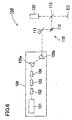
- Fig. 6 illustrates a schematic structure of the laser apparatus 150.
- a medical laser apparatus for cornea ablation using a wavelength-converted beam in the ultraviolet region will follow, with reference to Fig. 6.
- An Nd:YAG solid laser light source 101, wavelength converter elements 102, 103 and 104, and a pair of prisms 105a and 105b are arranged in a laser light source unit 100 provided in the laser apparatus 150.
- the solid laser light source 101 emits a pulse laser beam of 1064 nm.
- the wavelength converter element 102 generates a converted beam of 532 nm in wavelength by converting a fundamental wave beam of 1064 nm in wavelength into its second harmonic.
- the wavelength converter element 103 generates a converted beam of 266 nm in wavelength by converting the converted beam of 532 nm to its second harmonic.
- the wavelength converter element 104 generates a converted beam of 213 nm in wavelength, which is the sum-frequency beam of the wavelength 1064 nm of the components not converted by the wavelength converter element 102 and the wavelength 266 nm converted by the wavelength converter element 103.
- the QPM crystal quartz 10 shown in Fig. 1 are used as the wavelength converter elements 103 and 104 for wavelength conversion into the ultraviolet region.
- the wavelength converter element 102 a KTP crystal or the like can be used, but the same QPM crystal quartz 10 can be used as well.
- the prism 105a separates the laser beams of different wavelengths from one another. Out of the laser beams separated by the prism 105a, that of 213 nm in wavelength comes incident on the prism 105b, and other beams are shielded by a shield element (not shown). The laser beam of 213 nm in wavelength, as the beam for therapeutic use, is adjusted in the output direction, and emitted from the laser light source unit 100.
- a guiding optical system 110 is provided with a scanning optical system consisting of two galvano-mirrors 111 and 112 and a dichroic mirror 113.
- the dichroic mirror 113 has a characteristic of reflecting a laser beam of 213 nm and transmitting visible beams.
- a laser beam scanned at high speed by the two galvano-mirrors 111 and 112 is then reflected by the dichroic mirror 113 to be guided to a cornea Ec of the patient's eye.
- the optical system on the optical path from the laser light source unit 100 to the galvano-mirror 111 is not illustrated, a mirror for reflecting the laser beam, an optical system for shaping the laser beam into a circular spot, and a corrective optical system for correcting its energy distribution are appropriately arranged.
- the spot size of the laser beam in this laser apparatus 150 should be about 1 mm on the cornea Ec.
- an observation optical system 120 Over the dichroic mirror 113 is arranged an observation optical system 120,
- a control unit (not shown) obtains control data for laser irradiation on the basis of the corneal surgery data. For instance, where myopia is to be corrected, a combination of superposition of a pulse laser and the number of pulses (duration of irradiation) is used as the control data for laser irradiation for ablation which is to be deep in the central part of the cornea Ec and progressively shallower toward the periphery.
- An ultraviolet beam of 213 nm is supplied from the laser light source unit 100 by the wavelength conversion described above, and scanning operations by the galvano-mirrors 111 and 112 controlled on the basis of the control data guide the laser beam onto the cornea Ec. This causes the cornea Ec to be ablated into the desired shape.
- wavelength conversion by the QPM crystal quartz 10 is applicable in particular to laser apparatuses which conduct wavelength conversion to laser beams in the ultraviolet region, and suitable for use in laser apparatuses for medical use.
- control of twins in crystal quartz can be improved and the growth of twins realized in a high aspect ratio. Furthermore, it enables wavelength conversion of ultraviolet rays for practical purposes and its suitable application to laser apparatuses for medical use.
Landscapes
- Physics & Mathematics (AREA)
- Nonlinear Science (AREA)
- General Physics & Mathematics (AREA)
- Optics & Photonics (AREA)
- Optical Modulation, Optical Deflection, Nonlinear Optics, Optical Demodulation, Optical Logic Elements (AREA)
- Crystals, And After-Treatments Of Crystals (AREA)
Abstract
Description
Claims (10)
- A manufacturing method for quasi phase matching (QPM) wavelength converter elements (10) using crystal quartz (11) as a base material in which twins (12) are periodically induced, characterized by comprising:a step of periodically inducing the twins by applying a stress onto a crystal quartz substrate (30) as the base material so that an angle of a direction in which the stress is applied relative to a Z axis of the crystal quartz (11) is 60° < < 90°.
- The manufacturing method according to claim 1, wherein
the angle is 80° ≤ ≤ 88°. - The manufacturing method according to claim 1 or 2, further comprising
a step of forming, on a surface on the crystal quartz substrate, preferably a stress application side of the surface on the crystal quartz substrate, a stepped structure (31) with a periodicity for realizing a desired wavelength conversion. - A manufacturing method for quasi phase matching (QPM) wavelength converter elements (10) using crystal quartz (11) as a base material in which twins (12) are periodically induced, comprising:a stress application step of periodically inducing the twins by applying a stress onto a crystal quartz substrate (30) as the base material; anda heat treatment step of keeping a temperature between two planes of the crystal quartz substrate (30) orthogonal to a direction in which the stress is applied at or below a phase transition temperature of the crystal quartz and creating a temperature difference between the two planes.
- The manufacturing method according to claim 4, further comprising
a step of forming, on a surface on the crystal quartz substrate, preferably a stress application side of the surface on the crystal quartz substrate, a stepped structure (31) with a periodicity for realizing a desired wavelength conversion, and
T1 > T2 holds at the heat treatment step where T1 is a temperature of a stepped structure side of the two planes and T2 is a temperature of the other side. - The manufacturing method according to claim 5, wherein
at the heat treatment step, the temperature T1 is kept higher than 250°C and lower than 475°C and the temperature T2 is kept below 225°C. - The manufacturing method according to claim 5 or 6, wherein
at the heat treatment step, the temperature T2 is so controlled as to stop the twins, which grow from the stepped structure side, from growing in a direction of a Y axis of the crystal quartz before they reach the other side. - A quasi phase matching (QPM) wavelength converter element (10) whose base material is crystal quartz (11) in which twins (12) are periodically induced by applying a stress, wherein
interfaces (12a) of the twins (12) are formed in a plane containing a Y axis of the crystal quartz (11) and the twins (12) are formed in a direction of a Z axis of the crystal quartz (11) periodically. - The QPM wavelength converter element (10) according to claim 8, wherein an angle α formed by the direction of the Z axis of the crystal quartz (11) and an incidence vector of a fundamental wave beam (20) is 0° ≤ α ≤ 30°.
- A medical laser apparatus (150) comprising a laser light source (101) and a wavelength converter element (102-104) for converting the wavelength of a laser beam from the laser light source, characterized in that
the wavelength converter element is the QPM wavelength converter element according to claim 8 or 9.
Applications Claiming Priority (4)
| Application Number | Priority Date | Filing Date | Title |
|---|---|---|---|
| JP2003069035A JP4666449B2 (en) | 2003-03-14 | 2003-03-14 | Manufacturing method of quasi phase matching wavelength conversion element |
| JP2003069036 | 2003-03-14 | ||
| JP2003069036A JP4739655B2 (en) | 2003-03-14 | 2003-03-14 | Pseudo phase matching wavelength conversion element, method for manufacturing the same, and medical laser apparatus using the same |
| JP2003069035 | 2003-03-14 |
Publications (3)
| Publication Number | Publication Date |
|---|---|
| EP1457814A2 true EP1457814A2 (en) | 2004-09-15 |
| EP1457814A3 EP1457814A3 (en) | 2005-01-05 |
| EP1457814B1 EP1457814B1 (en) | 2008-02-13 |
Family
ID=32775277
Family Applications (1)
| Application Number | Title | Priority Date | Filing Date |
|---|---|---|---|
| EP04005582A Expired - Lifetime EP1457814B1 (en) | 2003-03-14 | 2004-03-09 | Method of manufacturing a QPM wavelength converter device |
Country Status (3)
| Country | Link |
|---|---|
| US (2) | US7329316B2 (en) |
| EP (1) | EP1457814B1 (en) |
| DE (1) | DE602004011694T2 (en) |
Cited By (3)
| Publication number | Priority date | Publication date | Assignee | Title |
|---|---|---|---|---|
| US8264766B2 (en) | 2007-04-18 | 2012-09-11 | Nikon Corporation | Wavelength conversion element, wavelength conversion method, phase matching method, and light source device |
| CN102822735A (en) * | 2010-03-26 | 2012-12-12 | 株式会社尼康 | Optical element, light source device, and optical element production method |
| CN113406837A (en) * | 2021-06-08 | 2021-09-17 | 南京邮电大学 | Method for realizing quasi-phase matching multi-wavelength frequency multiplication conversion |
Families Citing this family (4)
| Publication number | Priority date | Publication date | Assignee | Title |
|---|---|---|---|---|
| JP2006189587A (en) * | 2005-01-05 | 2006-07-20 | Nidek Co Ltd | Medical laser apparatus |
| JP6324452B2 (en) * | 2016-08-19 | 2018-05-16 | 大学共同利用機関法人自然科学研究機構 | Pulsed light generator |
| JP2021039236A (en) * | 2019-09-03 | 2021-03-11 | 大学共同利用機関法人自然科学研究機構 | Crystal element and manufacturing method thereof, and optical oscillator including crystal element |
| CN111425164B (en) * | 2020-03-30 | 2021-04-06 | 中国石油大学(华东) | Fully-electrically-driven underground safety valve and digital twin control method and system thereof |
Family Cites Families (12)
| Publication number | Priority date | Publication date | Assignee | Title |
|---|---|---|---|---|
| GB601243A (en) * | 1946-01-23 | 1948-04-30 | Gen Electric Co Ltd | Improvements in the manufacture of piezo-electric crystals |
| GB580965A (en) * | 1943-09-14 | 1946-09-26 | Gen Electric Co Ltd | Improvements in the manufacture of piezo-electric crystals |
| US3932777A (en) * | 1974-11-29 | 1976-01-13 | Bliley Electric Company | Vacuum electrolysis of quartz |
| JP2750231B2 (en) * | 1990-11-05 | 1998-05-13 | 富士通株式会社 | Method of manufacturing waveguide type second harmonic generation element |
| US5264959A (en) * | 1992-11-25 | 1993-11-23 | The United States Of America As Represented By The United States Department Of Energy | Temperature-insensitive phase-matched optical harmonic conversion crystal |
| US5835650A (en) * | 1995-11-16 | 1998-11-10 | Matsushita Electric Industrial Co., Ltd. | Optical apparatus and method for producing the same |
| US5960259A (en) * | 1995-11-16 | 1999-09-28 | Matsushita Electric Industrial Co., Ltd. | Optical apparatus and method for producing the same |
| US6428532B1 (en) * | 1998-12-30 | 2002-08-06 | The General Hospital Corporation | Selective tissue targeting by difference frequency of two wavelengths |
| JP2002276002A (en) * | 2001-03-12 | 2002-09-25 | Matsushita Electric Ind Co Ltd | Toilet equipment |
| JP2003075876A (en) * | 2001-08-30 | 2003-03-12 | Nidek Co Ltd | Cornea operation device |
| JP2004109916A (en) * | 2002-09-20 | 2004-04-08 | Nikon Corp | Wavelength converter for optical communication |
| JP2004109914A (en) * | 2002-09-20 | 2004-04-08 | Nikon Corp | Method for manufacturing quasi-phase matched crystal and quasi-phase matched crystal |
-
2004
- 2004-03-09 US US10/795,255 patent/US7329316B2/en not_active Expired - Fee Related
- 2004-03-09 DE DE602004011694T patent/DE602004011694T2/en not_active Expired - Lifetime
- 2004-03-09 EP EP04005582A patent/EP1457814B1/en not_active Expired - Lifetime
-
2007
- 2007-10-05 US US11/905,933 patent/US7878205B2/en not_active Expired - Fee Related
Cited By (7)
| Publication number | Priority date | Publication date | Assignee | Title |
|---|---|---|---|---|
| US8264766B2 (en) | 2007-04-18 | 2012-09-11 | Nikon Corporation | Wavelength conversion element, wavelength conversion method, phase matching method, and light source device |
| US8422120B2 (en) | 2007-04-18 | 2013-04-16 | Nikon Corporation | Wavelength conversion element, wavelength conversion method, phase matching method, and light source device |
| CN102822735A (en) * | 2010-03-26 | 2012-12-12 | 株式会社尼康 | Optical element, light source device, and optical element production method |
| EP2555050A4 (en) * | 2010-03-26 | 2014-01-22 | Nikon Corp | OPTICAL ELEMENT, LIGHT SOURCE DEVICE, AND METHOD FOR MANUFACTURING OPTICAL ELEMENT |
| US9140958B2 (en) | 2010-03-26 | 2015-09-22 | Nikon Corporation | Optical element, light source device, and optical element production method |
| CN113406837A (en) * | 2021-06-08 | 2021-09-17 | 南京邮电大学 | Method for realizing quasi-phase matching multi-wavelength frequency multiplication conversion |
| CN113406837B (en) * | 2021-06-08 | 2022-07-01 | 南京邮电大学 | Method for realizing quasi-phase matching multi-wavelength frequency multiplication conversion |
Also Published As
| Publication number | Publication date |
|---|---|
| US20080046043A1 (en) | 2008-02-21 |
| EP1457814B1 (en) | 2008-02-13 |
| US7878205B2 (en) | 2011-02-01 |
| US7329316B2 (en) | 2008-02-12 |
| DE602004011694T2 (en) | 2008-06-12 |
| DE602004011694D1 (en) | 2008-03-27 |
| US20040181212A1 (en) | 2004-09-16 |
| EP1457814A3 (en) | 2005-01-05 |
Similar Documents
| Publication | Publication Date | Title |
|---|---|---|
| US7878205B2 (en) | Manufacturing method for QPM wavelength converter elements, QPM wavelength converter element, and medical laser apparatus using it | |
| EP1063049B1 (en) | Apparatus with an optical system for laser heat treatment and method for producing semiconductor devices by using the same | |
| CN1148154C (en) | Short pulse mid-infrared parameter generator for surgery | |
| CN101461039B (en) | Laser processing method | |
| EP2465634B1 (en) | Laser machining device and laser machining method | |
| EP2460614A1 (en) | Laser scribe processing method | |
| JPH09507724A (en) | Diode-pumped multi-axis mode intracavity doubling laser | |
| JP2002205180A (en) | Laser processing method | |
| EP3417515B1 (en) | High efficiency laser system for third harmonic generation | |
| WO1998041177A9 (en) | Short pulse mid-infrared parametric generator for surgery | |
| CN115718395B (en) | A method for high-efficiency femtosecond laser-induced ferroelectric domain engineering | |
| WO2020131652A1 (en) | Method for manufacturing of patterned srb4bo7 and pbb4o7 crystals | |
| US20030012540A1 (en) | Method for producing optical waveguides, optical waveguides and frequency converting devices | |
| CN1568564A (en) | Temperature actuated positioning device for non-linear optical elements | |
| JP4666449B2 (en) | Manufacturing method of quasi phase matching wavelength conversion element | |
| US7164525B2 (en) | Wavelength converting devices | |
| JP4739655B2 (en) | Pseudo phase matching wavelength conversion element, method for manufacturing the same, and medical laser apparatus using the same | |
| JPH11335199A (en) | Production of single crystal membrane | |
| JPH1130792A (en) | Wavelength conversion element for Ar laser | |
| JP2003075876A (en) | Cornea operation device | |
| Webjörn et al. | Periodically domain-inverted lithium niobate channel waveguides for second harmonic generation | |
| US6526072B1 (en) | Wavelength conversion device composed of single-crystal lithium tetraborate, laser apparatus provided with the same and method of converting wavelength using the same | |
| Lipatiev et al. | Writing LaBGeO5 Crystal-in-Glass Waveguide and Tailoring Its Cross-Section by Femtosecond Laser Beam | |
| JP3412901B2 (en) | Laser oscillator | |
| JPH06310794A (en) | Method for stabilizing output of ultraviolet laser light and ultraviolet laser light generator |
Legal Events
| Date | Code | Title | Description |
|---|---|---|---|
| PUAI | Public reference made under article 153(3) epc to a published international application that has entered the european phase |
Free format text: ORIGINAL CODE: 0009012 |
|
| AK | Designated contracting states |
Kind code of ref document: A2 Designated state(s): AT BE BG CH CY CZ DE DK EE ES FI FR GB GR HU IE IT LI LU MC NL PL PT RO SE SI SK TR |
|
| AX | Request for extension of the european patent |
Extension state: AL LT LV MK |
|
| PUAL | Search report despatched |
Free format text: ORIGINAL CODE: 0009013 |
|
| AK | Designated contracting states |
Kind code of ref document: A3 Designated state(s): AT BE BG CH CY CZ DE DK EE ES FI FR GB GR HU IE IT LI LU MC NL PL PT RO SE SI SK TR |
|
| AX | Request for extension of the european patent |
Extension state: AL LT LV MK |
|
| 17P | Request for examination filed |
Effective date: 20050527 |
|
| 17Q | First examination report despatched |
Effective date: 20050704 |
|
| AKX | Designation fees paid |
Designated state(s): DE FR GB |
|
| GRAP | Despatch of communication of intention to grant a patent |
Free format text: ORIGINAL CODE: EPIDOSNIGR1 |
|
| RTI1 | Title (correction) |
Free format text: METHOD OF MANUFACTURING A QPM WAVELENGTH CONVERTER DEVICE |
|
| GRAS | Grant fee paid |
Free format text: ORIGINAL CODE: EPIDOSNIGR3 |
|
| GRAJ | Information related to disapproval of communication of intention to grant by the applicant or resumption of examination proceedings by the epo deleted |
Free format text: ORIGINAL CODE: EPIDOSDIGR1 |
|
| 17Q | First examination report despatched |
Effective date: 20050704 |
|
| GRAP | Despatch of communication of intention to grant a patent |
Free format text: ORIGINAL CODE: EPIDOSNIGR1 |
|
| GRAS | Grant fee paid |
Free format text: ORIGINAL CODE: EPIDOSNIGR3 |
|
| GRAA | (expected) grant |
Free format text: ORIGINAL CODE: 0009210 |
|
| AK | Designated contracting states |
Kind code of ref document: B1 Designated state(s): DE FR GB |
|
| REG | Reference to a national code |
Ref country code: GB Ref legal event code: FG4D |
|
| REF | Corresponds to: |
Ref document number: 602004011694 Country of ref document: DE Date of ref document: 20080327 Kind code of ref document: P |
|
| ET | Fr: translation filed | ||
| PLBE | No opposition filed within time limit |
Free format text: ORIGINAL CODE: 0009261 |
|
| STAA | Information on the status of an ep patent application or granted ep patent |
Free format text: STATUS: NO OPPOSITION FILED WITHIN TIME LIMIT |
|
| 26N | No opposition filed |
Effective date: 20081114 |
|
| REG | Reference to a national code |
Ref country code: FR Ref legal event code: PLFP Year of fee payment: 13 |
|
| REG | Reference to a national code |
Ref country code: DE Ref legal event code: R082 Ref document number: 602004011694 Country of ref document: DE Representative=s name: PRUEFER & PARTNER MBB PATENTANWAELTE RECHTSANW, DE Ref country code: DE Ref legal event code: R081 Ref document number: 602004011694 Country of ref document: DE Owner name: NATIONAL INSTITUTE FOR MATERIALS SCIENCE, TSUK, JP Free format text: FORMER OWNERS: NIDEK CO., LTD., GAMAGORI-SHI, AICHI-KEN, JP; NATIONAL INSTITUTE FOR MATERIALS SCIENCE, TSUKUBA, IBARAKI, JP |
|
| REG | Reference to a national code |
Ref country code: FR Ref legal event code: PLFP Year of fee payment: 14 |
|
| REG | Reference to a national code |
Ref country code: GB Ref legal event code: 732E Free format text: REGISTERED BETWEEN 20170504 AND 20170510 |
|
| REG | Reference to a national code |
Ref country code: FR Ref legal event code: TP Owner name: NATIONAL INSTITUTE FOR MATERIALS SCIENCE, JP Effective date: 20170822 |
|
| REG | Reference to a national code |
Ref country code: FR Ref legal event code: PLFP Year of fee payment: 15 |
|
| PGFP | Annual fee paid to national office [announced via postgrant information from national office to epo] |
Ref country code: GB Payment date: 20190325 Year of fee payment: 16 Ref country code: FR Payment date: 20190326 Year of fee payment: 16 Ref country code: DE Payment date: 20190328 Year of fee payment: 16 |
|
| REG | Reference to a national code |
Ref country code: DE Ref legal event code: R119 Ref document number: 602004011694 Country of ref document: DE |
|
| PG25 | Lapsed in a contracting state [announced via postgrant information from national office to epo] |
Ref country code: FR Free format text: LAPSE BECAUSE OF NON-PAYMENT OF DUE FEES Effective date: 20200331 Ref country code: DE Free format text: LAPSE BECAUSE OF NON-PAYMENT OF DUE FEES Effective date: 20201001 |
|
| GBPC | Gb: european patent ceased through non-payment of renewal fee |
Effective date: 20200309 |
|
| PG25 | Lapsed in a contracting state [announced via postgrant information from national office to epo] |
Ref country code: GB Free format text: LAPSE BECAUSE OF NON-PAYMENT OF DUE FEES Effective date: 20200309 |