EP1457750A1 - Liquid drain for fluid conducting devices - Google Patents
Liquid drain for fluid conducting devices Download PDFInfo
- Publication number
- EP1457750A1 EP1457750A1 EP03005315A EP03005315A EP1457750A1 EP 1457750 A1 EP1457750 A1 EP 1457750A1 EP 03005315 A EP03005315 A EP 03005315A EP 03005315 A EP03005315 A EP 03005315A EP 1457750 A1 EP1457750 A1 EP 1457750A1
- Authority
- EP
- European Patent Office
- Prior art keywords
- liquid
- drain
- fluid
- fluid guide
- guide device
- Prior art date
- Legal status (The legal status is an assumption and is not a legal conclusion. Google has not performed a legal analysis and makes no representation as to the accuracy of the status listed.)
- Withdrawn
Links
Images

Classifications
-
- F—MECHANICAL ENGINEERING; LIGHTING; HEATING; WEAPONS; BLASTING
- F28—HEAT EXCHANGE IN GENERAL
- F28B—STEAM OR VAPOUR CONDENSERS
- F28B9/00—Auxiliary systems, arrangements, or devices
- F28B9/08—Auxiliary systems, arrangements, or devices for collecting and removing condensate
-
- F—MECHANICAL ENGINEERING; LIGHTING; HEATING; WEAPONS; BLASTING
- F28—HEAT EXCHANGE IN GENERAL
- F28F—DETAILS OF HEAT-EXCHANGE AND HEAT-TRANSFER APPARATUS, OF GENERAL APPLICATION
- F28F13/00—Arrangements for modifying heat-transfer, e.g. increasing, decreasing
- F28F13/04—Arrangements for modifying heat-transfer, e.g. increasing, decreasing by preventing the formation of continuous films of condensate on heat-exchange surfaces, e.g. by promoting droplet formation
-
- F—MECHANICAL ENGINEERING; LIGHTING; HEATING; WEAPONS; BLASTING
- F28—HEAT EXCHANGE IN GENERAL
- F28F—DETAILS OF HEAT-EXCHANGE AND HEAT-TRANSFER APPARATUS, OF GENERAL APPLICATION
- F28F17/00—Removing ice or water from heat-exchange apparatus
Definitions
- the invention relates to the removal of liquid from fluid-carrying devices, in particular from such facilities that are at least along one spatial direction have narrow channel cross sections and in which the fluid flow is limited driving forces (e.g. small pressure differences).
- the pressure drop between the fluid inlet and the fluid outlet is small, then: the forces exerted by the fluid flowing past on those deposited on the inner wall Liquid act, may not be sufficient to the interior walls liquid deposited or accumulating at the outlet ends to drive out of the channels. If this is the case, then this fluid carries, for example due to the formation of drops, at least in some areas to a narrowing of the channel cross section and / or to a constriction at the outlet end of the Channel. This reduces the effective flow cross-section within the channel and / or at the outlet end of the channel, whereby the flow properties of the fluid guide structure be deteriorated, causing impairment and possibly can even lead to a complete stoppage of a fluid flow.
- a typical example of fluid routing structures affected by such problems are plate heat exchangers like those used in many areas of technology for heating, Cooling, evaporation and condensing can be used.
- Such a plate heat exchanger consists of an arrangement of parallel plates, that define alternating flow areas for two fluids, for example a warmer fluid to be cooled (primary fluid) by a colder fluid (secondary fluid) is cooled without the two fluids coming into contact with one another.
- the fluids can be liquids, gases, or gas / liquid mixtures.
- the primary fluid lies at the heat exchanger inlet gaseous or as a two-phase mixture (Gas / liquid) and is partially or fully condensed in the heat exchanger.
- the fluid can also be a multi-component fluid from which only one or more components are partially or fully condensed.
- a typical example is humid air, which is cooled, part of the Water vapor is converted into liquid water.
- the plates of a plate heat exchanger can be plane-parallel and be spaced from each other. But you can also use a channel structure at least one side, either as a meandering structure or as parallel channels is formed so that the plates of the plate heat exchanger directly against each other can be stored.
- Miniature heat exchangers can have cross sections in the duct On the order of millimeters or fractions thereof. If heat exchanger with such small structures with a low volume flow and a low Pressure drop operated as condensers, condensate drops in the channels or at their ends. This phenomenon also occurs in particular Outlet end of the channels.
- the fluid guide device becomes a liquid drain device at an outlet end the fluid guide device is provided such that the distance between the liquid drain device and the outlet end of the fluid guide disappears or less than that required for automatic droplet detachment Distance.
- the liquid drain device When the distance between the liquid drain device and the outlet end of the fluid guiding device disappears, it is caused that at the outlet end No drop forms at all and the liquid immediately as a creeping film is transferred to the liquid drain device. If the liquid drain device within the distance required for automatic droplet detachment is arranged, it causes a drop that forms to be in contact arrives with the liquid drain device and detached from the outlet end by this without being the size required for automatic droplet detachment can reach. In this context, it should be noted that the for a automatic droplet detachment generally requires a distance from the geometry and orientation of the arrangement and the shape of the drops depends on and is orientation-dependent.
- Orientation generally relates to a positioning of the liquid drain device to understand the outlet end at which at least part of the liquid drain device is within the volume range that one is going through not yet replacing drop would be taken.
- the inventive method can constrict the outlet end be significantly reduced by liquid and occlusion of the outlet end can be avoided by drops of liquid.
- the liquid drain device and / or the fluid guiding device with a wetting promoting Provide coating are provided.
- a sponge-like material can advantageously be used as the liquid drain device be used at the outlet end of the fluid guide is provided such that the distance between the sponge-like material and the outlet end of the fluid guide device disappears or is smaller than the distance required for automatic droplet detachment. Because of the capillary effect the sponge-like material suppresses droplet formation particularly effectively and thereby promotes fluid drainage. Under "spongy" in Porous materials may also be included in the description of this invention.
- an arrangement of drain elements includes, which is designed according to the arrangement of free outlet ends is.
- the drain device can be: the outlet ends of the fluid guide are arranged so that each Drain element is provided at an outlet end of the fluid guide device is that the distance between each drain element of the liquid drain device and the corresponding outlet end of the fluid guide device disappears or less than that required for automatic droplet detachment Distance.
- Several drain elements can also be provided for each outlet end be, which can be particularly advantageous if the outlet end has no highly symmetrical cross-sectional profile, for example elongated is, and / or if the fluid drainage also with different orientations of the Fluid guide device should function reliably.
- the drain elements comprise a wetting-promoting surface.
- the liquid drain can the fluid guide device can be improved.
- the drain elements with a hydrophilic Form surface.
- the Drain elements slats that are provided at the outlet ends be it that they be attached there later, be it that they are integral with the corresponding Devices of the fluid guide device are formed.
- the liquid drain device is not physical connected to the outlet ends of the fluid guide device, but represents an independent Element, for example a mat, the drain elements in the Forms of pins that correspond to the arrangement of the outlet ends of the Fluid guide device are arranged.
- This liquid drain device can are arranged below the outlet ends of the fluid guide device in such a way that the distance between each pin of the liquid drain device and the corresponding outlet end of the fluid guide device is smaller than that for a automatic droplet detachment required distance. Drops on the outlet ends form and grow, come into contact with the pins and then become immediately derived by this. The distance between the pins and the outlet ends must be chosen so that the drops cannot reach a size, in which they noticeably narrow the omissions.
- the liquid drain device comprises a sponge-like material
- the entire liquid drainage device can be formed from the sponge-like material, or just the drain elements. Due to the capillary effect, the sponge-like material suppresses the Drop formation and promotes fluid drainage particularly effectively.
- the invention also provides plate elements for a plate heat exchanger.
- drain elements are on the outlet-side edge of this plate element provided for liquid, preferably integral with the plate member are trained.
- the use of such plate elements for construction a plate heat exchanger automatically leads to the formation of a liquid drain device, so that it does not have to be used afterwards.
- a vanishing distance between each drain element of the liquid drain device and the corresponding outlet end of the fluid guide device (Plate heat exchanger) so that liquid from the outlet end over the immediately following drain elements can be discharged without Thaw the outlet end.
- fully assembled fluid guiding devices are also integrated Liquid drainage facilities provided, so that a subsequent installation a liquid drain device is not required.
- the integrated liquid drain device can be an inventive one described above Be liquid drain device, the drain elements of the drain device so arranged with respect to the outlet ends of the fluid guide device are that the distances between the drain elements of the liquid drain device and the corresponding outlet ends of the fluid guide device disappear or less than that required for automatic droplet detachment Distance.
- the integrated liquid drain device can also be a sponge-like material be arranged with respect to the outlet ends of the fluid guide device that the distances between the outlet ends of the fluid guide and the spongy material disappears or is smaller than that for one automatic droplet detachment required distance.
- the benefits of sponge-like Materials for liquid drainage have already been mentioned several times and require no repetition here.
- heat exchangers with integrated liquid drain devices provided, in which the problems described above no longer exist.
- Figure 1 shows a plate capacitor 1 in a conventional mode of operation in a schematic Sectional view: plates 2 arranged in parallel form alternating flow areas for a primary fluid (fluid to be cooled) and a secondary fluid (cooling Fluid). These plates 2 are closed with end pieces 3 so that the fluids are not can come into direct contact with each other. The heat exchange takes place via the the flow separating plates 2.
- the plates 2 of the heat exchanger 1 can be substructures have, for example in the plate wall milled channels or ribs on the Panel walls.
- the condenser 1 has an inlet 4 on its upper side (top left in the figure) an outlet 5 for the primary fluid 6 and on the underside (bottom left in the figure) for the cooled primary fluid and for the liquid condensed out of the primary fluid on.
- the inlet and outlet for the secondary fluid 7 are not in the sectional view displayed.
- the flow of the secondary fluid 7 takes place in the example outlined Plate capacitor perpendicular to the plane of the drawing.
- the fluid to be cooled is warm, humid air and the cooling fluid is cooling air, for example ambient air.
- the moist air When flowing through the condenser 1, the moist air is cooled and thereby a Part of the gaseous phase of the air to be cooled is converted into liquid water.
- the water condenses on the walls of the condenser and becomes under the action of gravity and / or the air flowing past in the direction of the Missing driven.
- the condensate is collected in a drain pan 8 and passed to the outlet 5 and can there to a water separator or Intermediate tank are performed.
- the sketched illustration of FIG. 1 further shows liquid drops 9 at the outlet end of channels.
- the shape of the drops depends on the cross-sectional shape of the channels so that their shape is very different from an ordinary round teardrop shape, e.g. the shape of a free-falling drop or the shape of a drop on a flat surface adhering drop.
- the surface tension and thus the drop size at which detachment occurs depend on the liquid and the wall material, but also on the geometric Conditions (e.g. channel shape and diameter, radii of curvature of the edges at the outlet end), the surface roughness of the channels and the temperature.
- the liquid that collects at the outlet end causes small duct cross-sections a non-negligible narrowing of the duct cross-section at the outlet end and leads to an increase in flow resistance for the flowing past Fluid. This leads to a reduction in the volume flow and thus to reduce the effectiveness of the capacitor.
- droplet formation can be caused by a hydrophilic coating or another surface treatment that increases wetting become.
- a hydrophilic coating or another surface treatment that increases wetting become.
- Figure 2 now illustrates a first embodiment of a solution according to the invention of this problem.
- a drain device 200 which has an arrangement of drain elements 210 which correspond to the Arrangement of free outlet ends of the channels for the fluid to be cooled is formed is.
- the drain elements 210 are designed as pins that are in place when the drain device is inserted 200 in the drain pan 8 of the heat exchanger 1 just as far extend above that the distance between the pins of the liquid drain device and the respective outlet end of the fluid guide device is smaller than that distance required for automatic droplet detachment.
- the liquid drops 9 in the arrangement of FIG. 2 at the outlet end do not grow until they reach a size at which an automatic, i.d.R. drop detachment essentially caused by the weight. Rather, the surfaces of the growing drops come before they are reached this size in contact with the pins, with each corresponding drop (or at least most of the amount of liquid in the drop) from the outlet end detached and fed through the drain elements 210 of the floor pan.
- the drain device 200 is shown in a top view in the lower part of the figure. Since the An elongated rectangular cross-sectional profile at the outlet ends of a plate capacitor , there are several for each outlet end (in the sketched example: three) drainage elements (pins) 200 are provided to prevent excessive drop growth prevent along the entire cross-sectional profile.
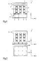
- FIG. 3 A second embodiment of the invention to solve the above The problem is outlined in FIG. 3.
- the drain device 300 is formed by lamella-like drain elements 310 which are provided at the outlet ends of the channels and extend into the floor pan 8 of the plate capacitor 1. Because these slats are attached directly to the outlet ends, the distance between the liquid drain device and the outlet end of the fluid guide device.
- these slats extend the panels in sections beyond the actual outlet end into the floor pan 8, so that Water can be continuously discharged through the slats to the floor pan and does not have to come loose from the outlet end in the form of free drops.
- Adjacent plates are preferably arranged opposite one another, so that a Drop can run between a pair of slats.
- the lamellar drain elements 310 can (subsequently) on the plates of the Capacitor can be attached, alternatively - and particularly preferred - but can the individual plates of the condenser including drain elements 310 be made in one piece.
- drain elements 310 of FIG. 3 is only an example to understand. For a channel to function properly, it is important that at least a portion of the outlet end is permeable to the inflowing gas remains, i.e. remains above the fluid play in the floor pan and not through Drops are clogged.
- An alternative form of drain elements is shown in FIG. 4.
- FIG. 4 shows a plate element 402 according to the principles of the present invention, a plurality of such plate elements 402 for forming a plate capacitor be used.
- the plate element 402 has tapered drain elements on its underside 410, the drain elements 410 being an integral part of the plate element 402 are.
- the drain elements 410 being an integral part of the plate element 402 are.
- the triangle tips on the bottom 8b of the floor pan of the capacitor.
- the liquid level is indicated by a dashed horizontal Line indicated. Between the outlet end and the liquid level Free triangular areas are formed, through which gas exits the channels can, while liquid over the drain elements partially immersed in the liquid 410 can run out of the channels.
- Structures 415 are also provided in the walls of the sketched plate 402, which promote that which condenses on the plate walls and runs downwards Liquid flows off in the direction of the sections with drain elements 410, whereby overall a faster drainage of the condensate can be achieved.
- a liquid drain device 510 is positioned across the bottom of the channels the outlet ends in the floor pan (not shown), so that they with the lower edges of the plates 2 are in contact or there is a distance from them, which is smaller than the distance required for automatic droplet detachment.
- a liquid-absorbing substance on the plates When condensing instead of drops, a thin film of liquid forms on this layer further condensate flows down without droplet formation, and there via the drainage structure is derived.
- These layers can be made using conventional thin film techniques (e.g. vapor deposition) or by appropriate mechanical application become. The same effect can also be applied by applying thin absorbent Materials such as absorbent membranes or fleece can be achieved.
- Materials for the drainage structure are particularly suitable for fabrics that have a high wettability with the condensate, for example hydrophilic ceramics in water, Sponges or materials with well wettable coatings.
- the invention is based on the following physical principles: To make a drop To expel a canal, the drop must be pushed out at the end of the canal become. In doing so, its surface area is increased until it reaches its mass and so that the gravitational force acting on the drop is large enough to cohesive forces and overcome surface tension and thereby the drop replace. If now a drain device with a suitable surface (advantageous promoting wetting, e.g. hydrophilic) on the lower edge of the channels or slightly is spaced e.g. if tips protrude into the channels, the condensate comes already in contact with the drain device during the initial formation of the drop and causes the condensate to drain without the channel being closed becomes. If there is a gap between the drain and the channels, a drop forms that bulges out of the channel and when touched with the drain device running on this.
- a suitable surface promoting wetting, e.g. hydrophilic
Abstract
Description
Die Erfindung betrifft die Abfuhr von Flüssigkeit aus fluidführenden Einrichtungen, insbesondere aus solchen Einrichtungen, die wenigstens entlang einer Raumrichtung enge Kanalquerschnitte aufweisen und bei denen die Fluidführung unter geringen treibenden Kräften (z.B. geringen Druckunterschieden) erfolgt.The invention relates to the removal of liquid from fluid-carrying devices, in particular from such facilities that are at least along one spatial direction have narrow channel cross sections and in which the fluid flow is limited driving forces (e.g. small pressure differences).
Bei fluidführenden Einrichtungen mit - im Vergleich zur Tropfengröße oder der Dicke eines Flüssigkeitsfilms - großen Kanalquerschnitten werden die fluidführenden Eigenschaften kaum beeinträchtigt, wenn sich innerhalb der Kanäle Flüssigkeit niederschlägt (als Film oder in Tropfenform) oder sich am Auslassende der Kanäle Tropfen bilden.In fluid-carrying devices with - compared to the drop size or thickness of a liquid film - large channel cross sections become the fluid-carrying properties hardly affected if liquid condenses inside the channels (as a film or in drops) or drops at the outlet end of the channels form.
Auch bei kleineren Kanalquerschnitten stellt die Abfuhr von Flüssigkeit aus den fluidführenden Kanälen, speziell von Flüssigkeit, die sich an den Innenwänden dieser Kanäle niedergeschlagen hat, in der Regel kein Problem dar, falls die Fluide mit einem hohen Druckunterschied zwischen Fluideinlass und Fluidauslass durch die Fluidführungsstruktur getrieben werden. Die entsprechend hohe Strömungsgeschwindigkeiten des (laminar oder turbulent) strömenden Fluids können dann Flüssigkeit "mitreißen", die sich beispielsweise aufgrund von Kondensation an den Innenwänden niederschlägt, so dass sich Flüssigkeit nicht nennenswert an den Innenwänden oder an den Auslassenden ansammeln kann.Even with smaller channel cross sections, the removal of liquid from the fluid-carrying Channels, especially of liquid, that are on the inner walls of these channels has usually not been a problem if the fluids with a high pressure difference between fluid inlet and fluid outlet through the fluid guide structure to be driven. The correspondingly high flow rates of the (laminar or turbulent) flowing fluid can then "carry away" liquid, which, for example, condenses on the inner walls, so that liquid is not appreciably on the inner walls or on the Can accumulate outlet ends.
Ist dagegen der Druckabfall zwischen Fluideinlass und Fluidauslass gering, so können die Kräfte, die durch das vorbeiströmende Fluid auf die an der Innenwand niedergeschlagene Flüssigkeit wirken, unter Umständen nicht ausreichen, um an den Innenwänden niedergeschlagene oder sich an den Auslassenden ansammelnde Flüssigkeit aus den Kanälen auszutreiben. Wenn dies der Fall ist, so führt diese Flüssigkeit, beispielweise aufgrund von Tropfenbildung, wenigstens bereichsweise zu einer Verengung des Kanalquerschnitts und/oder zu einer Einschnürung am Auslassende des Kanals. Dies verringert den effektiven Strömungsquerschnitt innerhalb des Kanals und/oder am Auslassende des Kanals, wodurch die Strömungseigenschaften der Fluidführungsstruktur verschlechtert werden, was zur Beeinträchtigung und gegebenenfalls sogar bis hin zu einem völligen Erliegen einer Fluidströmung führen kann.If, on the other hand, the pressure drop between the fluid inlet and the fluid outlet is small, then: the forces exerted by the fluid flowing past on those deposited on the inner wall Liquid act, may not be sufficient to the interior walls liquid deposited or accumulating at the outlet ends to drive out of the channels. If this is the case, then this fluid carries, for example due to the formation of drops, at least in some areas to a narrowing of the channel cross section and / or to a constriction at the outlet end of the Channel. This reduces the effective flow cross-section within the channel and / or at the outlet end of the channel, whereby the flow properties of the fluid guide structure be deteriorated, causing impairment and possibly can even lead to a complete stoppage of a fluid flow.
Ein typisches Beispiel für von derartigen Problemen betroffene Fluidführungsstrukuren sind Plattenwärmetauscher, wie sie heute in vielen Bereichen der Technik beim Heizen, Kühlen, Verdampfen und Kondensieren verwendet werden.A typical example of fluid routing structures affected by such problems are plate heat exchangers like those used in many areas of technology for heating, Cooling, evaporation and condensing can be used.
Ein solcher Plattenwärmetauscher besteht aus einer Anordnung von parallelen Platten, die alternierende Strömungsbereiche für zwei Fluide definieren, wobei beispielsweise ein wärmeres, zu kühlendes Fluid (Primärfluid) durch ein kälteres Fluid (Sekundärfluid) gekühlt wird, ohne dass die beiden Fluide miteinander in Kontakt gelangen. Die Fluide können Flüssigkeiten, Gase, oder Gas/Flüssigkeits-Gemische sein.Such a plate heat exchanger consists of an arrangement of parallel plates, that define alternating flow areas for two fluids, for example a warmer fluid to be cooled (primary fluid) by a colder fluid (secondary fluid) is cooled without the two fluids coming into contact with one another. The fluids can be liquids, gases, or gas / liquid mixtures.
Bei der Verwendung eines Plattenwärmetauscher als Kondensator liegt das Primärfluid am Wärmetauschereingang gasförmig oder als Zweiphasengemisch (Gas/Flüssigkeit) vor und wird im Wärmetauscher teilweise oder vollständig kondensiert. Bei dem Fluid kann es sich auch um ein mehrkomponentiges Fluid handeln, aus dem nur eine oder mehrere Komponenten teilweise oder vollständig kondensiert werden. Ein typisches Beispiel ist feuchte Luft, welche gekühlt wird, wobei ein Teil des Wasserdampfes in flüssiges Wasser umgewandelt wird.When using a plate heat exchanger as a condenser, the primary fluid lies at the heat exchanger inlet gaseous or as a two-phase mixture (Gas / liquid) and is partially or fully condensed in the heat exchanger. The fluid can also be a multi-component fluid from which only one or more components are partially or fully condensed. A typical example is humid air, which is cooled, part of the Water vapor is converted into liquid water.
Die Platten eines Plattenwärmetauschers können im einfachsten Fall planparallel und voneinander beabstandet sein. Sie können aber auch eine Kanalstruktur auf wenigstens einer Seite aufweisen, die entweder als Mäanderstruktur oder als parallele Kanäle ausgebildet ist, so dass die Platten des Plattenwärmetauschers direkt aneinander gelagert werden können. Kleinstwärmetauscher können Kanalquerschnitte in der Größenordnung von Millimetern oder Bruchteilen davon aufweisen. Wenn Wärmetauscher mit solch kleinen Strukturen bei einem geringen Volumenstrom und einem geringen Druckabfall als Kondensatoren betrieben werden, halten sich Kondensattropfen in den Kanälen oder an deren Enden. Dieses Phänomen tritt insbesondere auch am Auslassende der Kanäle auf.In the simplest case, the plates of a plate heat exchanger can be plane-parallel and be spaced from each other. But you can also use a channel structure at least one side, either as a meandering structure or as parallel channels is formed so that the plates of the plate heat exchanger directly against each other can be stored. Miniature heat exchangers can have cross sections in the duct On the order of millimeters or fractions thereof. If heat exchanger with such small structures with a low volume flow and a low Pressure drop operated as condensers, condensate drops in the channels or at their ends. This phenomenon also occurs in particular Outlet end of the channels.
Aufgrund der Oberflächenspannung ist ein an einem benetzbaren Material haftender Tropfen energetisch günstiger als ein freier Tropfen der gleichen Größe. Daher muss zum Ablösen des Tropfens vom Auslassende des Kanals Energie aufgebracht, d.h. Arbeit geleistet werden. Diese Arbeit verrichten die am Tropfen durch das vorbeiströmende Fluid angreifenden Kräfte und die Gravitationskraft. Da diese Kräfte umso größer sind, je größer der Tropfen ist, kommt es ab einer bestimmten Tropfengröße zu einer Tropfenablösung.Due to the surface tension, it adheres to a wettable material Drops energetically cheaper than a free drop of the same size. Therefore must applied energy to detach the drop from the outlet end of the channel, i.e. Work to be done. This work is done by the droplets flowing through Fluid attacking forces and gravitational force. Because these forces are all the greater are, the larger the drop, it comes from a certain drop size a drop detachment.
Speziell bei kleinen Kanalquerschnitten, die für hohe, der Tropfenablösung entgegenwirkende Kapillarkräfte sorgen, und/oder bei kleinen Druckunterschieden (d.h. geringen Fluidströmungsgeschwindigkeiten) kann diese, zur Tropfenablösung erforderliche Tropfengröße aber so groß sein, dass noch nicht abgelöste Tropfen, die diese Größe noch nicht erreicht haben oder aufgrund der geometrischen Einschränkungen nicht erreichen können, entweder den gesamten Kanal blockieren oder den Kanalquerschnitt stark einengen. In diesen Fällen wird das Nachströmen weiteren Fluids stark beeinträchtigt bis verhindert. Durch das Blockieren oder Einengen einzelner Kanäle wird die gesamte aktive Wärmetauscherfläche reduziert, was letztendlich zu einem Erliegen der Funktionsfähigkeit des Wärmetauschers führen kann.Especially in the case of small channel cross-sections that counteract the drop detachment Capillary forces and / or small pressure differences (i.e. small Fluid flow velocities) this can be necessary for droplet detachment Drop size but should be so large that undissolved drops are of this size have not yet reached or due to the geometric restrictions can either block the entire channel or the channel cross-section severely restrict. In these cases, the flow of additional fluids becomes strong impaired to prevented. By blocking or restricting individual channels the total active heat exchanger area is reduced, which ultimately leads to a Failure of the functionality of the heat exchanger can result.
Es ist Aufgabe der vorliegenden Erfindung, Lösungen zur Vermeidung der oben beschriebenen Probleme bereitzustellen. Diese Aufgabe wird durch das erfindungsgemäße Verfahren und die erfindungsgemäßen Einrichtungen gelöst. Vorteilhafte Weiterbildungen sind in den Unteransprüchen angegeben.It is an object of the present invention to find solutions to avoid the above To provide problems. This object is achieved by the invention Method and the devices according to the invention solved. Advantageous further training are specified in the subclaims.
Gemäß dem erfindungsgemäßen Verfahren zur Abfuhr von Flüssigkeit aus einer Fluidführungseinrichtung wird eine Flüssigkeitsablaufeinrichtung an einem Auslassende der Fluidführungseinrichtung derart vorgesehen, dass der Abstand zwischen der Flüssigkeitsablaufeinrichtung und dem Auslassende der Fluidführungseinrichtung verschwindet oder kleiner ist als der für eine selbsttätige Tropfenablösung erforderliche Abstand.According to the method according to the invention for removing liquid from a fluid guide device becomes a liquid drain device at an outlet end the fluid guide device is provided such that the distance between the liquid drain device and the outlet end of the fluid guide disappears or less than that required for automatic droplet detachment Distance.
Dabei bezeichnet "selbsttätige Tropfenablösung" den Zustand, in dem sich der Tropfen alleine unter Einwirken des vorbeiströmenden Fluids und/oder der Gravitationskraft vom Auslassende loslösen würde. "Automatic droplet detachment" refers to the state in which the drop is solely under the influence of the flowing fluid and / or the gravitational force would detach from the outlet end.
Wenn der Abstand zwischen der Flüssigkeitsablaufeinrichtung und dem Auslassende der Fluidführungseinrichtung verschwindet, so wird bewirkt, dass sich am Auslassende überhaupt kein Tropfen bildet und die Flüssigkeit als kriechender Film unmittelbar auf die Flüssigkeitsablaufeinrichtung übergeführt wird. Wenn die Flüssigkeitsablaufeinrichtung innerhalb des für eine selbsttätige Tropfenablösung erforderlichen Abstands angeordnet wird, so wird bewirkt, dass ein sich bildender Tropfen in Berührung mit der Flüssigkeitsablaufeinrichtung gelangt und durch diese vom Auslassende abgelöst wird, ohne dass er die für die selbsttätige Tropfenablösung erforderliche Größe erreichen kann. Es sei in diesem Zusammenhang darauf verwiesen, dass der für eine selbsttätige Tropfenablösung erforderliche Abstand im Allgemeinen von der Geometrie und Orientierung der Anordnung und der Tropfenform abhängt und somit richtungs- und orientierungsabhängig ist. Unter einem Abstand, der kleiner ist, als der für eine selbsttätige Tropfenablösung erforderliche Abstand, ist also bei einer gegebenen Orientierung allgemein eine Positionierung der Flüssigkeitsablaufeinrichtung bezüglich dem Auslassende zu verstehen, bei der sich wenigstens ein Teil der Flüssigkeitsablaufeinrichtung innerhalb des Volumenbereichs befindet, dass durch einen sich gerade noch nicht ablösenden Tropfens eingenommen werden würde.When the distance between the liquid drain device and the outlet end of the fluid guiding device disappears, it is caused that at the outlet end No drop forms at all and the liquid immediately as a creeping film is transferred to the liquid drain device. If the liquid drain device within the distance required for automatic droplet detachment is arranged, it causes a drop that forms to be in contact arrives with the liquid drain device and detached from the outlet end by this without being the size required for automatic droplet detachment can reach. In this context, it should be noted that the for a automatic droplet detachment generally requires a distance from the geometry and orientation of the arrangement and the shape of the drops depends on and is orientation-dependent. At a distance smaller than that for an automatic droplet detachment is required for a given distance Orientation generally relates to a positioning of the liquid drain device to understand the outlet end at which at least part of the liquid drain device is within the volume range that one is going through not yet replacing drop would be taken.
Durch das erfindungsgemäße Verfahren kann eine Einschnürung des Auslassendes durch Flüssigkeit beträchtlich verringert werden und ein Verschließen des Auslassendes durch Flüssigkeitstropfen vermieden werden.The inventive method can constrict the outlet end be significantly reduced by liquid and occlusion of the outlet end can be avoided by drops of liquid.
Gemäß einer bevorzugten Weiterbildung des Verfahrens wird die Flüssigkeitsablaufeinrichtung und/oder die Fluidführungseinrichtung mit einer benetzungsfördernden Beschichtung versehen.According to a preferred development of the method, the liquid drain device and / or the fluid guiding device with a wetting promoting Provide coating.
In den Kanälen der Fluidführungseinrichtung bewirkt dies, dass sich anstelle von Tropfen auf den Wänden dünne Flüssigkeitsfilme bilden, die das Strömungsprofil weit weniger beeinträchtigen als Tropfen. An der Flüssigkeitsablaufeinrichtung bewirkt eine benetzungsfördernde Beschichtung ein schnelleres Ablaufen von Flüssigkeit. Handelt es sich bei der Flüssigkeit um Wasser oder wässrige Lösungen, so werden als benetzungsfördernde Beschichtung besonders vorteilhaft hydrophile Substanzen eingesetzt; bei öligen Flüssigkeiten bevorzugt lipophile Substanzen. Alternativ können die entsprechenden Einrichtungen ganz aus benetzungsfördernden Materialien hergestellt sein.In the channels of the fluid guiding device, this causes that instead of Drops on the walls form thin films of liquid that extend the flow profile affect less than drops. A causes at the liquid drain device wetting-promoting coating a faster drainage of liquid. These If the liquid is water or aqueous solutions, it is said to promote wetting Coating particularly advantageously used hydrophilic substances; preferred lipophilic substances for oily liquids. Alternatively, the appropriate facilities made entirely of wetting-promoting materials his.
Es wird darauf hingewiesen, dass alle herkömmlichen Einrichtungen als Flüssigkeitsablaufeinrichtung verwendet werden können, die entsprechend dem oben beschriebenen Verfahren einsetzbar sind.It should be noted that all conventional devices as a liquid drain device can be used according to the above Procedures can be used.
Insbesondere kann vorteilhaft ein schwammartiges Material als Flüssigkeitsablaufeinrichtung verwendet werden, das an dem Auslassende der Fluidführungseinrichtung derart vorgesehen wird, dass der Abstand zwischen dem schwammartigen Material und dem Auslassende der Fluidführungseinrichtung verschwindet oder kleiner ist als der für eine selbsttätige Tropfenablösung erforderliche Abstand. Aufgrund des Kapillareffekts unterdrückt das schwammartige Material die Tropfenbildung besonders effektiv und begünstigt dadurch die Flüssigkeitsabfuhr. Unter "schwammartig" sollen im Rahmen der Beschreibung dieser Erfindung auch poröse Materialien umfasst sein.In particular, a sponge-like material can advantageously be used as the liquid drain device be used at the outlet end of the fluid guide is provided such that the distance between the sponge-like material and the outlet end of the fluid guide device disappears or is smaller than the distance required for automatic droplet detachment. Because of the capillary effect the sponge-like material suppresses droplet formation particularly effectively and thereby promotes fluid drainage. Under "spongy" in Porous materials may also be included in the description of this invention.
Besonders für Fluidführungseinrichtungen mit einer Anordnung von Auslassenden schlagen die Erfinder aber speziell ausgestaltete Flüssigkeitsablaufeinrichtungen vor, wobei eine derartige Flüssigkeitsablaufeinrichtung eine Anordnung von Ablaufelementen umfasst, die entsprechend der Anordnung von freien Auslassenden ausgebildet ist.Especially for fluid guidance devices with an arrangement of outlet ends However, the inventors propose specially designed liquid drainage devices, such a liquid drain device an arrangement of drain elements includes, which is designed according to the arrangement of free outlet ends is.
Entsprechend dem erfindungsgemäßen Verfahren kann die Ablaufeinrichtung bezüglich den Auslassenden der Fluidführungseinrichtung so angeordnet werden, dass jedes Ablaufelement an einem Auslassende der Fluidführungseinrichtung derart vorgesehen ist, dass der Abstand zwischen jedem Ablaufelement der Flüssigkeitsablaufeinrichtung und dem entsprechenden Auslassende der Fluidführungseinrichtung verschwindet oder kleiner ist als der für eine selbsttätige Tropfenablösung erforderliche Abstand. Es können für jedes Auslassende auch mehrere Ablaufelemente vorgesehen sein, was insbesondere dann Vorteile mit sich bringen kann, wenn das Auslassende kein hochsymmetrisches Querschnittsprofil hat, beispielsweise längsgestreckt ist, und/oder wenn die Flüssigkeitsabfuhr auch bei verschiedenen Orientierungen der Fluidführungseinrichtung zuverlässig funktionieren soll. According to the method according to the invention, the drain device can be: the outlet ends of the fluid guide are arranged so that each Drain element is provided at an outlet end of the fluid guide device is that the distance between each drain element of the liquid drain device and the corresponding outlet end of the fluid guide device disappears or less than that required for automatic droplet detachment Distance. Several drain elements can also be provided for each outlet end be, which can be particularly advantageous if the outlet end has no highly symmetrical cross-sectional profile, for example elongated is, and / or if the fluid drainage also with different orientations of the Fluid guide device should function reliably.
In einer bevorzugten Weiterbildung der Ablaufeinrichtung umfassen die Ablaufelemente eine benetzungsfördernde Oberfläche. Hierdurch kann die Flüssigkeitsabfuhr aus der Fluidführungseinrichtung verbessert werden.In a preferred development of the drain device, the drain elements comprise a wetting-promoting surface. As a result, the liquid drain can the fluid guide device can be improved.
Demgemäß ist es bei Fluidführungseinrichtung mit Wasser oder wasserhaltigen Flüssigkeitsmischungen besonders vorteilhaft, die Ablaufelemente mit einer hydrophilen Oberfläche auszubilden.Accordingly, it is the case with a fluid guide device with water or water-containing liquid mixtures particularly advantageous, the drain elements with a hydrophilic Form surface.
In einer bevorzugten Weiterbildung der Flüssigkeitsablaufeinrichtung umfassen die Ablaufelemente Lamellen, die an den Auslassenden vorgesehen sind, sei es, dass sie dort nachträglich angebracht werden, sei es, dass sie integral mit entsprechenden Einrichtungen der Fluidführungseinrichtung ausgebildet sind. Bei dieser Weiterbildung liegt also ein verschwindender Abstand zwischen jedem Ablaufelement der Flüssigkeitsablaufeinrichtung und dem entsprechenden Auslassende der Fluidführungseinrichtung vor, so dass Flüssigkeit vom Auslassende über die unmittelbar anschließenden Lamellen abgeführt werden kann und somit ein Blockieren des Auslassendes vermieden werden kann.In a preferred development of the liquid drain device, the Drain elements slats that are provided at the outlet ends, be it that they be attached there later, be it that they are integral with the corresponding Devices of the fluid guide device are formed. With this training there is a vanishing distance between each drain element of the liquid drain device and the corresponding outlet end of the fluid guide device before, so that liquid from the outlet end to the immediately following Slats can be removed and thus blocking the outlet end can be avoided.
In einer alternativen Weiterbildung ist die Flüssigkeitsablaufeinrichtung physisch nicht mit den Auslassenden der Fluidführungseinrichtung verbunden, sondern stellt ein eigenständiges Element dar, beispielsweise eine Matte, das Ablaufelemente in der Form von Stiften umfasst, die entsprechend der Anordnung der Auslassenden der Fluidführungseinrichtung angeordnet sind. Diese Flüssigkeitsablaufeinrichtung kann unterhalb den Auslassenden der Fluidführungseinrichtung so angeordnet werden, dass der Abstand zwischen jedem Stift der Flüssigkeitsablaufeinrichtung und dem entsprechenden Auslassende der Fluidführungseinrichtung kleiner ist als der für eine selbsttätige Tropfenablösung erforderliche Abstand. Tropfen, die sich an den Auslassenden bilden und anwachsen, geraten mit den Stiften in Kontakt und werden dann sogleich durch diese abgeleitet. Der Abstand zwischen den Stiften und den Auslassenden muss so gewählt werden, dass die Tropfen keine Größe erreichen können, bei der sie die Auslassenden spürbar verengen.In an alternative development, the liquid drain device is not physical connected to the outlet ends of the fluid guide device, but represents an independent Element, for example a mat, the drain elements in the Forms of pins that correspond to the arrangement of the outlet ends of the Fluid guide device are arranged. This liquid drain device can are arranged below the outlet ends of the fluid guide device in such a way that the distance between each pin of the liquid drain device and the corresponding outlet end of the fluid guide device is smaller than that for a automatic droplet detachment required distance. Drops on the outlet ends form and grow, come into contact with the pins and then become immediately derived by this. The distance between the pins and the outlet ends must be chosen so that the drops cannot reach a size, in which they noticeably narrow the omissions.
In einer besonders bevorzugten Weiterbildung umfasst die Flüssigkeitsablaufeinrichtung ein schwammartiges Material, wobei die gesamte Flüssigkeitsablaufeinrichtung aus dem schwammartigen Material gebildet sein kann, oder auch nur die Ablaufelemente. Aufgrund des Kapillareffekts unterdrückt das schwammartige Material die Tropfenbildung und fördert die Flüssigkeitsabfuhr besonders effektiv.In a particularly preferred development, the liquid drain device comprises a sponge-like material, the entire liquid drainage device can be formed from the sponge-like material, or just the drain elements. Due to the capillary effect, the sponge-like material suppresses the Drop formation and promotes fluid drainage particularly effectively.
Die Erfindung stellt ferner Plattenelemente für einen Plattenwärmetauscher bereit. Erfindungsgemäß sind an der auslassseitigen Kante dieses Plattenelements Ablaufelemente für Flüssigkeit vorgesehen, die vorzugsweise integral mit dem Plattenelement ausgebildet sind. Die Verwendung derartiger Plattenelemente zur Konstruktion eines Plattenwärmetauschers führt automatisch zur Ausbildung einer Flüssigkeitsablaufeinrichtung, so dass eine solche nicht nachträglich eingesetzt werden muss. Auch hier liegt ein verschwindender Abstand zwischen jedem Ablaufelement der Flüssigkeitsablaufeinrichtung und dem entsprechenden Auslassende der Fluidführungseinrichtung (Plattenwärmetauscher) vor, so dass Flüssigkeit vom Auslassende über die unmittelbar anschließenden Ablaufelemente abgeführt werden kann, ohne sich am Auslassende aufzustauen.The invention also provides plate elements for a plate heat exchanger. According to the invention, drain elements are on the outlet-side edge of this plate element provided for liquid, preferably integral with the plate member are trained. The use of such plate elements for construction a plate heat exchanger automatically leads to the formation of a liquid drain device, so that it does not have to be used afterwards. Also here is a vanishing distance between each drain element of the liquid drain device and the corresponding outlet end of the fluid guide device (Plate heat exchanger) so that liquid from the outlet end over the immediately following drain elements can be discharged without Thaw the outlet end.
Erfindungsgemäß werden ferner fertig montierte Fluidführungseinrichtungen mit integrierten Flüssigkeitsablaufeinrichtungen bereitgestellt, so dass ein nachträglicher Einbau einer Flüssigkeitsablaufeinrichtung nicht erforderlich ist.According to the invention, fully assembled fluid guiding devices are also integrated Liquid drainage facilities provided, so that a subsequent installation a liquid drain device is not required.
Die integrierte Flüssigkeitsablaufeinrichtung kann eine oben beschriebenen erfindungsgemäße Flüssigkeitsablaufeinrichtung sein, wobei die Ablaufelemente der Ablaufeinrichtung bezüglich der Auslassenden der Fluidführungseinrichtung so angeordnet sind, dass die Abstände zwischen den Ablaufelementen der Flüssigkeitsablaufeinrichtung und den entsprechenden Auslassenden der Fluidführungseinrichtung verschwinden oder kleiner sind als der für eine selbsttätige Tropfenablösung erforderliche Abstand.The integrated liquid drain device can be an inventive one described above Be liquid drain device, the drain elements of the drain device so arranged with respect to the outlet ends of the fluid guide device are that the distances between the drain elements of the liquid drain device and the corresponding outlet ends of the fluid guide device disappear or less than that required for automatic droplet detachment Distance.
Die integrierte Flüssigkeitsablaufeinrichtung kann aber auch ein schwammartiges Material sein, das bezüglich der Auslassenden der Fluidführungseinrichtung so angeordnet wird, dass die Abstände zwischen den Auslassenden der Fluidführungseinrichtung und dem schwammartigen Material verschwinden oder kleiner sind als der für eine selbsttätige Tropfenablösung erforderliche Abstand. Die Vorteile von schwammartigen Materialien bei der Flüssigkeitsabfuhr wurden bereits mehrfach erwähnt und bedürfen hier keiner Wiederholung.The integrated liquid drain device can also be a sponge-like material be arranged with respect to the outlet ends of the fluid guide device that the distances between the outlet ends of the fluid guide and the spongy material disappears or is smaller than that for one automatic droplet detachment required distance. The benefits of sponge-like Materials for liquid drainage have already been mentioned several times and require no repetition here.
Insbesondere werden Wärmetauscher mit integrierten Flüssigkeitsablaufeinrichtungen bereitgestellt, bei denen somit die eingangs beschriebenen Probleme nicht mehr bestehen.In particular, heat exchangers with integrated liquid drain devices provided, in which the problems described above no longer exist.
Zur besseren Veranschaulichung der Erfindung wird diese nun anhand der beigefügten Figuren von besonders bevorzugten Ausführungsbeispielen erläutert.To better illustrate the invention, it will now be described with reference to the accompanying Figures of particularly preferred embodiments explained.
- Figur 1Figure 1
- zeigt einen Schnitt durch einen herkömmlichen Plattenkondensator;shows a section through a conventional plate capacitor;
- Figur 2Figure 2
- zeigt eine erste bevorzugte Ausbildung einer Ablaufeinrichtung für einen Plattenkondensator;shows a first preferred embodiment of a drain device for a plate condenser;
- Figur 3Figure 3
- zeigt eine zweite bevorzugte Ausführungsform einer Ablaufeinrichtung für einen Plattenkondensator;shows a second preferred embodiment of a drain device for a plate capacitor;
- Figur 4Figure 4
- zeigt eine dritte bevorzugte erfindungsgemäße Ausführungsform, bei der Ablaufelemente in eine Platte für einen Plattenkondensator integriert ist;shows a third preferred embodiment of the invention, in the drain elements is integrated in a plate for a plate capacitor;
- Figur 5Figure 5
- zeigt eine Anwendung des erfindungsgemäßen Verfahrens auf den herkömmlichen Plattenkondensator von Figur 1.shows an application of the inventive method to the conventional Plate capacitor of Figure 1
Figur 1 zeigt einen Plattenkondensator 1 in herkömmlicher Betriebsweise in schematischer
Schnittansicht: parallel angeordnete Platten 2 bilden alternierende Strömungsbereiche
für ein Primärfluid (zu kühlendes Fluid) und ein Sekundärfluid (kühlendes
Fluid). Diese Platten 2 sind mit Endstücken 3 so abgeschlossen, dass die Fluide nicht
direkt miteinander in Kontakt gelangen können. Der Wärmeaustausch erfolgt über die
die Strömungsbereiche trennenden Platten 2. Um die effektive wärmeaustauschende
Fläche zu vergrößern, können die Platten 2 des Wärmetauschers 1 Unterstrukturen
aufweisen, beispielsweise in die Plattenwand gefräste Kanäle oder Rippen an den
Plattenwänden.Figure 1 shows a
Der Kondensator 1 weist an seiner Oberseite (in der Figur links oben) einen Einlass 4
für das Primärfluid 6 und an der Unterseite (in der Figur links unten) einen Auslass 5
für das gekühlte Primärfluid und für die aus dem Primärfluid auskondensierte Flüssigkeit
auf. Einlass und Auslass für das Sekundärfluid 7 sind in der Schnittansicht nicht
abgebildet. Die Strömung des Sekundärfluids 7 erfolgt beim skizzierten beispielhaften
Plattenkondensator senkrecht zur Zeichenebene.The
Zur Vereinfachung der Beschreibung, aber ohne Einschränkung der Allgemeinheit, wird nachfolgend angenommen, dass das zu kühlende Fluid warme, feuchte Luft und das kühlende Fluid Kühlluft, beispielsweise Umgebungsluft, ist.To simplify the description, but without restricting generality, It is subsequently assumed that the fluid to be cooled is warm, humid air and the cooling fluid is cooling air, for example ambient air.
Beim Durchströmen des Kondensators 1 wird die feuchte Luft gekühlt und dadurch ein
Teil des in der gasförmigen Phase der zu kühlenden Luft in flüssiges Wasser umgewandelt.
Das Wasser kondensiert an den Wänden des Kondensators aus und wird
unter Wirkung von Gravitation und/oder der vorbeiströmenden Luft in Richtung des
Auslassendes getrieben. Das Kondensat wird in einer Ablaufwanne 8 aufgefangen
und zu dem Auslass 5 geleitet und kann dort zu einem Wasserabscheider oder einem
Zwischentank geführt werden.When flowing through the
Die skizzierte Darstellung von Figur 1 zeigt ferner Flüssigkeitstropfen 9 am Auslassende von Kanälen. Die Form der Tropfen hängt von der Querschnittsform der Kanäle ab, so dass ihre Gestalt sehr stark von einer gewöhnlichen rundlichen Tropfenform, z.B. der Form eines frei fallenden Tropfens oder Form eines auf einer ebenen Fläche haftenden Tropfens, abweichen kann.The sketched illustration of FIG. 1 further shows liquid drops 9 at the outlet end of channels. The shape of the drops depends on the cross-sectional shape of the channels so that their shape is very different from an ordinary round teardrop shape, e.g. the shape of a free-falling drop or the shape of a drop on a flat surface adhering drop.
Die Flüssigkeitstropfen 9 werden, insbesondere am Randbereich des Auslassendes, aufgrund der Oberflächenspannung (Grenzflächenspannung) festgehalten und wachsen dort so lange an, bis die Oberflächenspannung durch das Eigengewicht der Tropfen und Kräfte, die das vorbeiströmende Fluid auf die Tropfen ausübt, überkompensiert wird. The liquid drops 9, in particular at the edge region of the outlet end, held and grow due to the surface tension (interfacial tension) there until the surface tension is due to the weight of the drops and overcompensates forces that the flowing fluid exerts on the drops becomes.
Die Oberflächenspannung und damit die Tropfengröße, bei der ein Ablösen erfolgt, hängen von der Flüssigkeit und dem Wandmaterial ab, aber auch von den geometrischen Bedingungen (z.B. Kanalform und -durchmesser, Krümmungsradien der Kanten am Auslassende), der Oberflächenrauigkeit der Kanäle und der Temperatur.The surface tension and thus the drop size at which detachment occurs depend on the liquid and the wall material, but also on the geometric Conditions (e.g. channel shape and diameter, radii of curvature of the edges at the outlet end), the surface roughness of the channels and the temperature.
Die sich am Auslassende ansammelnde Flüssigkeit bewirkt bei kleinen Kanalquerschnitten einen nicht vernachlässigbare Verengung des Kanalquerschnitts am Auslassende und führt zu einer Erhöhung des Strömungswiderstands für das vorbeiströmende Fluid. Dadurch kommt es zu einer Verringerung des Volumenstroms und damit zu einer Verringerung der Effektivität des Kondensators.The liquid that collects at the outlet end causes small duct cross-sections a non-negligible narrowing of the duct cross-section at the outlet end and leads to an increase in flow resistance for the flowing past Fluid. This leads to a reduction in the volume flow and thus to reduce the effectiveness of the capacitor.
Bei sehr kleinen Kanalquerschnitten kann es sogar zu einem vollständigen Verschlieβen der Auslassenden kommen und damit, je nach Anzahl der verschlossenen Kanäle, zu einer starken Beeinträchtigung bis zu einer Aufhebung der Funktionsfähigkeit des Kondensators.With very small channel cross sections, it can even be completely closed of the dropouts come and, depending on the number of closed channels, to a severe impairment until the functional capacity is abolished of the capacitor.
Bis zu einem gewissen Ausmaß kann die Tropfenbildung durch eine hydrophile Beschichtung oder eine andere, die Benetzung erhöhende Oberflächenbehandlung reduziert werden. Vollständig können die oben genannten Probleme damit aber nicht eliminiert werden.To a certain extent, droplet formation can be caused by a hydrophilic coating or another surface treatment that increases wetting become. However, the above-mentioned problems cannot be completely solved be eliminated.
Figur 2 illustriert nun eine erste Ausführungsform einer erfindungsgemäßen Lösung dieses Problems.Figure 2 now illustrates a first embodiment of a solution according to the invention of this problem.
In der Ablaufwanne 8 des Wärmetauschers 1, der ansonsten mit dem Wärmetauscher
von Figur 1 identisch ist, ist eine erfindungsgemäße Ablaufeinrichtung 200 vorgesehen,
die eine Anordnung von Ablaufelementen 210 aufweist, die entsprechend der
Anordnung von freien Auslassenden der Kanäle für das zu kühlende Fluid ausgebildet
ist.In the
Die Ablaufelemente 210 sind als Stifte ausgebildet, die sich bei Einbringen der Ablaufeinrichtung
200 in die Ablaufwanne 8 des Wärmetauschers 1 gerade soweit nach
oben erstrecken, dass der Abstand zwischen den Stiften der Flüssigkeitsablaufeinrichtung
und dem jeweiligen Auslassende der Fluidführungseinrichtung kleiner ist als der
für eine selbsttätige Tropfenablösung erforderliche Abstand. Im Unterschied zur Figur
1 können die Flüssigkeitstropfen 9 bei der Anordnung von Figur 2 am Auslassende
nicht solange anwachsen, bis sie eine Größe erreichen, bei der eine selbsttätige,
i.d.R. im wesentlichen durch die Gewichtskraft bewirkte, Tropfenablösung erfolgt.
Vielmehr kommen die Oberflächen der anwachsenden Tropfen schon vor Erreichen
dieser Größe mit den Stiften in Berührung, wobei jeder entsprechende Tropfen (oder
wenigstens der größte Teil der Flüssigkeitsmenge des Tropfens) vom Auslassende
abgelöst und durch die Ablaufelemente 210 der Bodenwanne zugeführt wird.The
In der unteren Teilfigur ist die Ablaufeinrichtung 200 in Aufsicht dargestellt. Da die
Auslassenden eines Plattenkondensators ein langgestrecktes rechteckiges Querschnittsprofil
aufweisen, sind für jedes Auslassende mehrere (im skizzierten Beispiel:
drei) Ablaufelemente (Stifte) 200 vorgesehen, die das übermäßige Tropfenwachstum
entlang des gesamten Querschnittsprofils unterbinden.The
Eine zweite erfindungsgemäße Ausführungsform zur Lösung des oben beschriebenen Problems ist in Figur 3 skizziert.A second embodiment of the invention to solve the above The problem is outlined in FIG. 3.
Bei dieser Ausführungsform wird die Ablaufeinrichtung 300 durch lamellenartige Ablaufelemente
310 gebildet, die an den Auslassenden der Kanäle vorgesehen sind und
sich bis in die Bodenwanne 8 des Plattenkondensators 1 erstrecken. Da diese Lamellen
direkt an den Auslaufenden angebracht sind, verschwindet der Abstand zwischen
der Flüssigkeitsablaufeinrichtung und dem Auslassende der Fluidführungseinrichtung.In this embodiment, the drain device 300 is formed by lamella-like drain elements
310 which are provided at the outlet ends of the channels and
extend into the
Wie die rechte Teilfigur von Figur 3 zeigt, verlängern diese Lamellen die Platten abschnittsweise
über das eigentliche Auslassende hinaus in die Bodenwanne 8, so dass
Wasser kontinuierlich über die Lamellen zur Bodenwanne abgeführt werden kann und
sich nicht in Form freier Tropfen vom Auslassende lösen muss. Bei Plattenabständen
in der Größenordnung der Durchmesser von Flüssigkeitstropfen sind die Lamellen
benachbarter Platten bevorzugt einander gegenüberliegend angeordnet, so dass ein
Tropfen zwischen einem Lamellenpaar ablaufen kann.As the right part of Figure 3 shows, these slats extend the panels in sections
beyond the actual outlet end into the
Die lamellenartigen Ablaufelemente 310 können (nachträglich) an den Platten des Kondensators angebracht werden, alternativ - und besonders bevorzugt - aber können die einzelnen Platten des Kondensators einschließlich der Ablaufelemente 310 einstückig hergestellt werden.The lamellar drain elements 310 can (subsequently) on the plates of the Capacitor can be attached, alternatively - and particularly preferred - but can the individual plates of the condenser including drain elements 310 be made in one piece.
Zudem ist die rechteckige Zungenform der Ablaufelemente 310 von Figur 3 nur exemplarisch zu verstehen. Für die Funktionsfähigkeit eines Kanals ist es allein wichtig, dass wenigstens ein Teil des Auslassendes für nachströmendes Gas durchlässig bleibt, d.h. über dem Flüssigkeitsspiel in der Bodenwanne bleibt und auch nicht durch Tropfen verstopft wird. Eine alternative Form von Ablaufelementen zeigt Figur 4.In addition, the rectangular tongue shape of the drain elements 310 of FIG. 3 is only an example to understand. For a channel to function properly, it is important that at least a portion of the outlet end is permeable to the inflowing gas remains, i.e. remains above the fluid play in the floor pan and not through Drops are clogged. An alternative form of drain elements is shown in FIG. 4.
Figur 4 zeigt ein Plattenelement 402 nach den Prinzipien der vorliegenden Erfindung,
wobei eine Mehrzahl derartiger Plattenelemente 402 zur Ausbildung eines Plattenkondensators
verwendet werden.FIG. 4 shows a
Das Plattenelement 402 weist an seiner Unterseite in Dreiecksform zulaufende Ablaufelemente
410 auf, wobei die Ablaufelemente 410 integraler Bestandteil des Plattenelements
402 sind. Bei der Anordnung der Plattenelemente 402 zu einem Kondensator
können die Dreiecksspitzen beispielsweise auf dem Boden 8b der Bodenwanne
des Kondensators aufliegen. Der Flüssigkeitsspiegel ist durch eine gestrichelte horizontale
Linie angedeutet. Zwischen dem Auslassende und dem Flüssigkeitsspiegel
bilden sind freie dreiecksförmige Bereiche, über die Gas aus den Kanälen austreten
kann, während Flüssigkeit über die teilweise in die Flüssigkeit eintauchenden Ablaufelemente
410 aus den Kanälen ablaufen kann.The
In den Wänden der skizzierten Platte 402 sind außerdem Strukturen 415 vorgesehen,
die fördern, das an den Plattenwänden auskondensierende und nach unten ablaufende
Flüssigkeit in Richtung der Abschnitte mit Ablaufelementen 410 abfließt, wodurch
insgesamt ein schnelleres Ablaufen des Kondensats erreicht werden kann.
Fig. 5 skizziert die Anwendung des erfindungsgemäßen Verfahrens auf den herkömmlichen Plattenkondensator von Figur 1.5 outlines the application of the method according to the invention to the conventional one Plate capacitor of Figure 1
Eine Flüssigkeitsablaufeinrichtung 510 wird an der Unterseite der Kanäle quer über die Auslassenden in die (nicht abgebildete) Bodenwanne eingebracht, so dass sie mit den Unterkanten der Platten 2 in Kontakt steht oder ein Abstand zu diesen besteht, der kleiner ist als der für eine selbsttätige Tropfenablösung erforderliche Abstand.A liquid drain device 510 is positioned across the bottom of the channels the outlet ends in the floor pan (not shown), so that they with the lower edges of the plates 2 are in contact or there is a distance from them, which is smaller than the distance required for automatic droplet detachment.
Soll eine Tropfenbildung auf den Kondensationsplatten selbst vermieden werden oder die Ablaufeigenschaft des Kondensats an den Platten verbessert werden, bringt man auf den Platten eine flüssigkeitsabsorbierende Substanz auf. Beim Auskondensieren an dieser Schicht bildet sich an Stelle von Tropfen ein dünner Flüssigkeitsfilm, an den weiteres Kondensat ohne Tropfenbildung nach unten abfließt, und dort über die Ablaufstruktur abgeleitet wird. Diese Schichten können durch übliche Dünnschichttechniken (z.B. Bedampfen) oder durch entsprechendes mechanisches Auftragen aufgebracht werden. Der selbe Effekt kann auch durch Aufbringen von dünnen absorbierenden Materialien wie z.B. saugfähigen Membranen oder Fleece erreicht werden. Als Materialien für die Ablaufstruktur eignen sich besonders Stoffe, die eine hohe Benetzbarkeit mit dem Kondensat aufweisen, bei Wasser beispielsweise hydrophile Keramiken, Schwämme oder Materialien mit gut benetzbaren Beschichtungen.Should drip formation on the condensation plates themselves be avoided or the drainage properties of the condensate on the plates are improved a liquid-absorbing substance on the plates. When condensing instead of drops, a thin film of liquid forms on this layer further condensate flows down without droplet formation, and there via the drainage structure is derived. These layers can be made using conventional thin film techniques (e.g. vapor deposition) or by appropriate mechanical application become. The same effect can also be applied by applying thin absorbent Materials such as absorbent membranes or fleece can be achieved. As Materials for the drainage structure are particularly suitable for fabrics that have a high wettability with the condensate, for example hydrophilic ceramics in water, Sponges or materials with well wettable coatings.
Auch wenn viele der oben genannten Ideen in Bezug auf einen Wärmetauscher in Form eines Plattenkondensators erläutert wurden, so wird doch darauf hingewiesen, dass sich die Erfindung nicht auf diese Anwendung beschränkt, sondern auch auf andere fluidführende Strukturen angewandt werden kann. Beispiele sind z.B. die Strömungskanäle sogenannter Flowfields, wie sie bei Brennstoffzellenstacks verwendet werden. Auch hier erfolgt die Flüssigkeitsdurchfuhr unter einem geringen Druckgradienten.Even if many of the above ideas regarding a heat exchanger come in Form of a plate capacitor have been explained, it is nevertheless pointed out that the invention is not limited to this application, but also to others fluid-carrying structures can be applied. Examples are e.g. the flow channels So-called flow fields, as used in fuel cell stacks become. Here, too, the liquid is passed through under a low pressure gradient.
Die Erfindung basiert auf folgenden physikalischen Prinzipien: Um einen Tropfen aus einem Kanal auszutreiben, muss der Tropfen am Ende des Kanals ausgeschoben werden. Dabei wird seine Oberfläche vergrößert, und zwar so lange, bis seine Masse und damit die auf den Tropfen wirkende Gravitationskraft groß genug ist, um die Kohäsionskräfte und Oberflächenspannung zu überwinden und den Tropfen dadurch abzulösen. Wenn nun eine Ablaufeinrichtung mit geeigneter Oberfläche (vorteilhaft benetzungsfördernd, z.B. hydrophil) an der Unterkante der Kanäle anliegt oder gering beabstandet ist, z.B. wenn Spitzen in die Kanäle hineinragen, so kommt das Kondensat schon bei der ansatzweisen Bildung des Tropfens mit der Ablaufeinrichtung in Berührung und bewirkt ein Abfließen des Kondensats, ohne dass der Kanal verschlossen wird. Wenn ein Abstand zwischen der Ablaufeinrichtung und den Kanälen besteht, bildet sich ein Tropfen, der sich aus dem Kanal herauswölbt und bei Berührung mit der Ablaufeinrichtung an dieser abläuft.The invention is based on the following physical principles: To make a drop To expel a canal, the drop must be pushed out at the end of the canal become. In doing so, its surface area is increased until it reaches its mass and so that the gravitational force acting on the drop is large enough to cohesive forces and overcome surface tension and thereby the drop replace. If now a drain device with a suitable surface (advantageous promoting wetting, e.g. hydrophilic) on the lower edge of the channels or slightly is spaced e.g. if tips protrude into the channels, the condensate comes already in contact with the drain device during the initial formation of the drop and causes the condensate to drain without the channel being closed becomes. If there is a gap between the drain and the channels, a drop forms that bulges out of the channel and when touched with the drain device running on this.
Der Schutzumfang der Erfindung ist nicht durch die Beschreibung der bevorzugten Ausführungsformen beschränkt, sondern allein durch den in den nachfolgenden Ansprüchen beschriebenen Sachverhalt definiert.The scope of the invention is not to be described by the description of the preferred ones Embodiments limited, but only by that in the following claims described circumstances.
Claims (13)
eine Flüssigkeitsablaufeinrichtung an einem Auslassende der Fluidführungseinrichtung derart vorgesehen wird, dass der Abstand zwischen der Flüssigkeitsablaufeinrichtung und dem Auslassende der Fluidführungseinrichtung verschwindet oder kleiner ist als der für eine selbsttätige Tropfenablösung erforderliche Abstand.Method for removing liquid from a fluid guiding device, wherein
a liquid drain device is provided at an outlet end of the fluid guide device such that the distance between the liquid drain device and the outlet end of the fluid guide device disappears or is smaller than the distance required for automatic droplet detachment.
Priority Applications (1)
| Application Number | Priority Date | Filing Date | Title |
|---|---|---|---|
| EP03005315A EP1457750A1 (en) | 2003-03-11 | 2003-03-11 | Liquid drain for fluid conducting devices |
Applications Claiming Priority (1)
| Application Number | Priority Date | Filing Date | Title |
|---|---|---|---|
| EP03005315A EP1457750A1 (en) | 2003-03-11 | 2003-03-11 | Liquid drain for fluid conducting devices |
Publications (1)
| Publication Number | Publication Date |
|---|---|
| EP1457750A1 true EP1457750A1 (en) | 2004-09-15 |
Family
ID=32748847
Family Applications (1)
| Application Number | Title | Priority Date | Filing Date |
|---|---|---|---|
| EP03005315A Withdrawn EP1457750A1 (en) | 2003-03-11 | 2003-03-11 | Liquid drain for fluid conducting devices |
Country Status (1)
| Country | Link |
|---|---|
| EP (1) | EP1457750A1 (en) |
Cited By (5)
| Publication number | Priority date | Publication date | Assignee | Title |
|---|---|---|---|---|
| FR2895788A1 (en) * | 2006-01-03 | 2007-07-06 | Commissariat Energie Atomique | Heat exchanger for use as reflux condenser, has fluid circulation circuit with lower edge comprising prominent zones towards bottom, where lower edge permits to deviate condensates towards zones |
| DE102006037977A1 (en) * | 2006-08-14 | 2008-02-21 | Webasto Ag | Cooling device for a vehicle |
| US8685586B2 (en) | 2004-12-08 | 2014-04-01 | Toyota Jidosha Kabushiki Kaisha | Fuel cell separator |
| DE112008000553B4 (en) | 2007-04-20 | 2019-05-29 | Toyota Jidosha Kabushiki Kaisha | Fuel cell separator and fuel cell |
| CN113739596A (en) * | 2021-07-22 | 2021-12-03 | 中国船舶重工集团公司第七一九研究所 | Compact heat exchanger |
Citations (7)
| Publication number | Priority date | Publication date | Assignee | Title |
|---|---|---|---|---|
| FR2095202A1 (en) * | 1970-06-12 | 1972-02-11 | Luft Kaltetechn K | Condensate discharge from gas charged heat - exchangers |
| US3868830A (en) * | 1973-08-31 | 1975-03-04 | Nasa | Condensate removal device for heat exchanger |
| EP0155772A1 (en) * | 1984-03-13 | 1985-09-25 | Costain Petrocarbon Limited | Heat exchanger |
| EP0324375A1 (en) * | 1988-01-14 | 1989-07-19 | Bayerische Motoren Werke Aktiengesellschaft, Patentabteilung AJ-3 | Evaporator of an air conditioning apparatus |
| US6102994A (en) * | 1997-03-20 | 2000-08-15 | Alliedsignal Inc. | Alumina-based hydrophilic antimicrobial coating |
| EP1170565A1 (en) * | 2000-07-05 | 2002-01-09 | Societe D'etudes Et De Constructions Aero-Navales | Heat exchanger with conduits for two fluids |
| EP1170556A1 (en) * | 2000-07-07 | 2002-01-09 | Astrium GmbH | Condensing heat exchanger |
-
2003
- 2003-03-11 EP EP03005315A patent/EP1457750A1/en not_active Withdrawn
Patent Citations (7)
| Publication number | Priority date | Publication date | Assignee | Title |
|---|---|---|---|---|
| FR2095202A1 (en) * | 1970-06-12 | 1972-02-11 | Luft Kaltetechn K | Condensate discharge from gas charged heat - exchangers |
| US3868830A (en) * | 1973-08-31 | 1975-03-04 | Nasa | Condensate removal device for heat exchanger |
| EP0155772A1 (en) * | 1984-03-13 | 1985-09-25 | Costain Petrocarbon Limited | Heat exchanger |
| EP0324375A1 (en) * | 1988-01-14 | 1989-07-19 | Bayerische Motoren Werke Aktiengesellschaft, Patentabteilung AJ-3 | Evaporator of an air conditioning apparatus |
| US6102994A (en) * | 1997-03-20 | 2000-08-15 | Alliedsignal Inc. | Alumina-based hydrophilic antimicrobial coating |
| EP1170565A1 (en) * | 2000-07-05 | 2002-01-09 | Societe D'etudes Et De Constructions Aero-Navales | Heat exchanger with conduits for two fluids |
| EP1170556A1 (en) * | 2000-07-07 | 2002-01-09 | Astrium GmbH | Condensing heat exchanger |
Cited By (6)
| Publication number | Priority date | Publication date | Assignee | Title |
|---|---|---|---|---|
| US8685586B2 (en) | 2004-12-08 | 2014-04-01 | Toyota Jidosha Kabushiki Kaisha | Fuel cell separator |
| FR2895788A1 (en) * | 2006-01-03 | 2007-07-06 | Commissariat Energie Atomique | Heat exchanger for use as reflux condenser, has fluid circulation circuit with lower edge comprising prominent zones towards bottom, where lower edge permits to deviate condensates towards zones |
| DE102006037977A1 (en) * | 2006-08-14 | 2008-02-21 | Webasto Ag | Cooling device for a vehicle |
| DE112008000553B4 (en) | 2007-04-20 | 2019-05-29 | Toyota Jidosha Kabushiki Kaisha | Fuel cell separator and fuel cell |
| CN113739596A (en) * | 2021-07-22 | 2021-12-03 | 中国船舶重工集团公司第七一九研究所 | Compact heat exchanger |
| CN113739596B (en) * | 2021-07-22 | 2023-08-08 | 中国船舶重工集团公司第七一九研究所 | Compact heat exchanger |
Similar Documents
| Publication | Publication Date | Title |
|---|---|---|
| EP0600191B1 (en) | Heat pipe | |
| EP2815186B1 (en) | Device for cooling and/or heat recovery | |
| DE102005062855B4 (en) | Lattice structure, use of lattice structure and container with lattice structure | |
| DE2657131A1 (en) | SURFACE CAPACITOR | |
| EP3129738B1 (en) | Liquid distributor and arrangement | |
| EP3572760B1 (en) | Package for heat and/or material transfer | |
| DE2708657C3 (en) | capacitor | |
| EP1457750A1 (en) | Liquid drain for fluid conducting devices | |
| DE102009012347A1 (en) | Filter assembly and a method for producing a filter assembly | |
| DE2708659A1 (en) | CAPACITOR | |
| DE102010041289B4 (en) | Material and heat exchanger plate and a material and heat exchange reactor with such a material and heat exchanger plate | |
| EP3535539B1 (en) | Installation unit for a device for treating a useful fluid with a working fluid | |
| DE102009045403B4 (en) | Device for separating gas and liquid and uses thereof | |
| EP3433544B1 (en) | Insert element for inserting into a device for humidifying, cleaning and/or cooling a fluid, in particular a gas, such as, for example, air | |
| DE102011005932B4 (en) | Fluidic system for bubble-free filling of a microfluidic filter chamber and method for bubble-free filling and method for filtering a liquid with such a system | |
| DE3741388C1 (en) | Filter device | |
| DE2438551B2 (en) | FOREIGN MATERIAL SEPARATOR FOR AN OIL CIRCULATION SYSTEM | |
| EP3690378B1 (en) | Installation element for a device for treating a usage fluid with a working fluid | |
| DE102020121609A1 (en) | Oil pan with oil drain plug | |
| DE2610427B2 (en) | WATER SEPARATION CELL FOR THE REMOVAL OF THE REACTION WATER FROM THE ELECTROLYTE FROM FUEL ELEMENTS AND FUEL BATTERIES | |
| DE10218274A1 (en) | Pleated plate for cross flow heat exchanger, has pleat profile with steep rising flanks and flatter falling flanks | |
| DE102015104959B4 (en) | Counterflow plate heat exchangers | |
| DE102021211228A1 (en) | heat exchanger | |
| DE3242531A1 (en) | Heat exchangers and method of de-icing the same | |
| AT517274B1 (en) | air humidifier |
Legal Events
| Date | Code | Title | Description |
|---|---|---|---|
| PUAI | Public reference made under article 153(3) epc to a published international application that has entered the european phase |
Free format text: ORIGINAL CODE: 0009012 |
|
| AK | Designated contracting states |
Kind code of ref document: A1 Designated state(s): AT BE BG CH CY CZ DE DK EE ES FI FR GB GR HU IE IT LI LU MC NL PT SE SI SK TR |
|
| AX | Request for extension of the european patent |
Extension state: AL LT LV MK RO |
|
| AKX | Designation fees paid | ||
| REG | Reference to a national code |
Ref country code: DE Ref legal event code: 8566 |
|
| STAA | Information on the status of an ep patent application or granted ep patent |
Free format text: STATUS: THE APPLICATION IS DEEMED TO BE WITHDRAWN |
|
| 18D | Application deemed to be withdrawn |
Effective date: 20050316 |