EP1457730A2 - Intruding object monitoring system - Google Patents
Intruding object monitoring system Download PDFInfo
- Publication number
- EP1457730A2 EP1457730A2 EP04004449A EP04004449A EP1457730A2 EP 1457730 A2 EP1457730 A2 EP 1457730A2 EP 04004449 A EP04004449 A EP 04004449A EP 04004449 A EP04004449 A EP 04004449A EP 1457730 A2 EP1457730 A2 EP 1457730A2
- Authority
- EP
- European Patent Office
- Prior art keywords
- warning
- monitoring
- region
- mobile
- dangerous source
- Prior art date
- Legal status (The legal status is an assumption and is not a legal conclusion. Google has not performed a legal analysis and makes no representation as to the accuracy of the status listed.)
- Granted
Links
Images







Classifications
-
- F—MECHANICAL ENGINEERING; LIGHTING; HEATING; WEAPONS; BLASTING
- F16—ENGINEERING ELEMENTS AND UNITS; GENERAL MEASURES FOR PRODUCING AND MAINTAINING EFFECTIVE FUNCTIONING OF MACHINES OR INSTALLATIONS; THERMAL INSULATION IN GENERAL
- F16P—SAFETY DEVICES IN GENERAL; SAFETY DEVICES FOR PRESSES
- F16P3/00—Safety devices acting in conjunction with the control or operation of a machine; Control arrangements requiring the simultaneous use of two or more parts of the body
- F16P3/12—Safety devices acting in conjunction with the control or operation of a machine; Control arrangements requiring the simultaneous use of two or more parts of the body with means, e.g. feelers, which in case of the presence of a body part of a person in or near the danger zone influence the control or operation of the machine
- F16P3/14—Safety devices acting in conjunction with the control or operation of a machine; Control arrangements requiring the simultaneous use of two or more parts of the body with means, e.g. feelers, which in case of the presence of a body part of a person in or near the danger zone influence the control or operation of the machine the means being photocells or other devices sensitive without mechanical contact
- F16P3/142—Safety devices acting in conjunction with the control or operation of a machine; Control arrangements requiring the simultaneous use of two or more parts of the body with means, e.g. feelers, which in case of the presence of a body part of a person in or near the danger zone influence the control or operation of the machine the means being photocells or other devices sensitive without mechanical contact using image capturing devices
Definitions
- the present invention relates to an intruding object monitoring system suitable for securing the safety of workers in a manufacturing scene and more particularly, it relates to an intruding object monitoring system monitoring intrusion or the like of a mobile object such as a person into a dangerous region based on image information obtained by a camera.
- This kind of intruding object monitoring system is used for securing the safety of workers in a manufacturing scene.
- the conventional intruding object monitoring system the following system is known.
- a camera mounted on a ceiling takes an image of a floor and existence of a mobile object is detected by processing the obtained image.
- a signal for generating a warning or stopping the machine is output.
- an image obtained by the similar method is processed and a mobile object in the image is followed so that its direction and speed are determined.
- a signal for generating a warning or stopping the machine is output (referring to Japanese Unexamined Patent Publication No. 5-261692, for example).
- the conventional intruding object monitoring system has the following problems.
- the intruding object monitoring systems monitor the mobile object having three-dimensional configuration originally in a two-dimensional image, a vision on the image is varied depending on a position of the mobile obj ect, so that an accurate position cannot be measured in some cases.
- This problem becomes conspicuous as the object moves away from the center of a viewing field, and that an image is distorted at a peripheral part of a lens, causing positional precision in monitoring the intruding object to deteriorate.
- a method of monitoring the obj ect by many cameras mounted on the ceiling is thought, costs is increased in this case so that it is not practical.
- the present invention was made in view of the above conventional problems and it is an object of the present invention to provide an intruding object monitoring system which can monitor an intruding object with high reliability with just one camera.
- An intruding object monitoring system comprises a camera mounted on a position so as to look down a monitoring target region including a dangerous source and an information processing apparatus performing information processes for monitoring an intruding obj ect based on a monitoring target region image taken by the camera.
- a specific relation is set between a mounting position of the camera and a position of the dangerous source. More specifically, the mounting position of the camera is determined so that the dangerous source is seen at the peripheral part of the viewing field of the camera.
- an intruding object monitoring system comprises a camera mounted on a position so as to look down a monitoring target region including a dangerous source, and an information processing apparatus performing information processes for monitoring an intruding object based on a monitoring target region image taken by the camera, and the dangerous source can be set only at a peripheral part of a viewing field of the camera.
- the peripheral part of the camera means that the dangerous source seen in the viewing field of the camera is positioned within a region of 1/3, preferably 1/4 of the whole length of the viewing field from the peripheral part in the vertical and lateral directions, respectively (hereinafter, referred to as a dangerous source settable region). At this time, the whole of the dangerous source is not necessarily seen in the viewing field and only a part of the dangerous source may be positioned at the peripheral part.
- the dangerous source When the dangerous source is set in the viewing field (the position of the dangerous source is registered in the monitoring system) , the dangerous source may be settable only in the dangerous source settable region and furthermore, the dangerous source may be settable only when it is in contact with the peripheral part of the viewing field.
- the dangerous source is arranged at the peripheral part of the viewing field, the floor just below the camera can be imaged. A configuration of the mobile object can be seen at the place just below the camera most accurately so that intrusion can be precisely detected at this place.
- the monitoring region can be largely secured so that the mobile object can be immediately pursued and a dangerous state can be immediately detected.
- the warning region in which the warning is generated at the time of intrusion
- the warning region can be easily arranged on the dangerous side from the place just below the camera. In this arrangement, risk of misjudgment in which intrusion is not detected even when the object actually intrudes into the warning region can be lowered.
- the intruding object monitoring system of the present invention since the mounting position of the camera is determined so that the dangerous source can be seen at the peripheral part of the viewing field of the camera, the monitoring target region image can be suitable for monitoring the intruding object.
- the intruding object can be monitored with higher reliability by employing various information processes for the obtained image information.
- a process for determining that a mobile object intrudes into a warning region set in the vicinity of the dangerous source by comparing a mobile object position in the monitoring target region image to a warning region position in the monitoring target region image on an image.
- the information processes for monitoring the intruding object performed in the information processing apparatus may comprise a process for immediately generating a warning in a case where a mobile obj ect intrudes into a warning region existing in the vicinity of the dangerous source, while for generating a warning only when speed of the mobile object toward the dangerous source exceeds a predetermined value in a case where the mobile object intrudes into a warning target region existing in the vicinity of the warning region.
- the warning is generated regardless of the condition when the person is in the region close to the dangerous source in which the person could get into touch with the machine in a prompt action, and the warning is generated depending on the direction and the speed of the object in the region apart from the dangerous source.
- the person can be kept safe without lowering an operation rate of the machine.
- the warning region is in the vicinity of the region just below the camera, the intrusion can be precisely detected.
- the precision as well as that in the warning region is not required in the warning target region.
- the information processes for monitoring the intruding object performed in the information processing apparatus may comprise a process for immediately generating the warning and then holding up the warning when the mobile obj ects whose number is more than a predetermined value intrude into the monitoring target region.
- the warning is held up when the mobile objects whose number exceeds the predetermined value intrude into the monitoring target region, the above problem can be avoided. Since the fact that many people exist in a limited space of a manufacturing scene is the problem itself in view of safety, this function is effective in this respect.
- the information processes for monitoring the intruding object performed in the information processing apparatus may comprise a process for monitoring only the mobile object existing in the warning region when the total number of the mobile objects existing in the warning region and the number of the mobile objects existing in the warning target region is more than a predetermined value.
- the information processes for monitoring the intruding object performed in the information processing apparatus may comprise a process for monitoring only the mobile objects whose number is a predetermined value and which are selected in increasing order of a distance from the dangerous source when the mobile objects whose number is more than the predetermined value intrude into the monitoring target region.
- the function (processing time or recognition precision) of the intruding object monitoring system can be maintained in only the process of monitoring the objects whose number is within the predetermined value.
- Fig. 1 shows a view of a hardware system constitution according to the present invention.
- reference character CA designates a camera (a video camera incorporating a CCD, a still camera or the like) which is an imaging device
- reference character PC designates a personal computer which is an information processing apparatus
- reference character B1 designates a board mounted on a personal computer PC to acquire an image
- reference character B2 designates a board for inputting and outputting a control signal
- reference character M designates a dangerous source such as a large-size machine
- reference character PB1 designates a push button switch for start and stop
- reference character PB2 designates a push button switch for canceling held-up warning.
- Image information is input from the camera CA to the image acquiring board B1.
- a facility signal from the dangerous source M a start/stop signal from the push button switch PB1 and a held-up warning canceling signal from the push button switch PB2 are input.
- a warning output signal for turning on a lamp L1 a warning region intrusion output signal for turning on a lamp L2
- a dangerous direction detection output signal for turning on a lamp L3 a detection inability output signal for turning on a lamp L4 and a warning target region intrusion output signal for turning on a lamp L5 and the like are output to the outside.
- Fig. 2 shows explanatory diagrams showing a relation between the camera and the dangerous source in which Fig. 2A shows a top view and Fig. 2B shows a side view.
- reference numeral 1 designates a floor
- reference numeral 2 designates an imaging region (a viewing field of the camera)
- reference numeral 3 designates a dangerous source
- reference numeral 4 designates a fence surrounding a right and left faces and back face of the dangerous source.
- the camera CA is mounted just above the monitoring target region. In other words, the camera CA is mounted at a place from which it can directly look down the monitoring target region.
- the camera CA has a rectangular imaging region (viewing field) 2.
- This imaging region (viewing field) 2 has a rectangular outline.
- the rectangular outline comprises a pair of short sides 2a and 2b and a pair of long sides 2c and 2d.
- a certain region S (a region designated by hatching in Fig. 2) on the inner periphery side of the pairs of short sides 2a and 2b and long sides 2c and 2d corresponds to a term, that is, "a peripheral part of the viewing field" in the present invention.
- the dangerous source 3 is arranged in the peripheral part S on the short side 2a of the imaging region (viewing field) 2 of the camera CA. Since the dangerous source 3 is surrounded by the fence 4 on the right and left sides and the back side, an intruding object can enter from the front side facing the camera CA. Namely, when a person approaches the dangerous source 3, the person surely moves away from the camera CA.
- a width (W1) of the peripheral part S in the vertical direction is shown by that (1/4) ⁇ W3 ⁇ W1 ⁇ (1/3) ⁇ W3.
- a width (W2) of the peripheral part S in the lateral direction is showy by that (1/4) ⁇ W4 ⁇ W1 ⁇ (1/3) ⁇ W4.
- Fig. 3 shows an explanatory diagram of an operation in a camera position according to the present invention, in which Fig. 3A shows a case of a system of the present invention and Fig. 3B shows a case of the conventional system.
- a dangerous source 3 is positioned just below the camera CA and the movement of a person P approaching the dangerous source 3 corresponds to the movement of the person P approaching the camera CA at the same time.
- reference numeral 2 designates an imaging region (a viewing field of the camera)
- reference numeral 3 designates the dangerous source
- reference numeral 5 designates a warning region.
- the arm of the person P is regarded as not intruding into the warning region 5 in the image of the camera and the warning is not generated.
- the dangerous source 3 exists in a position apart from a position just below the camera CA and the movement of the person P approaching the dangerous source 3 corresponds to the movement of the person P moving away from the camera CA.
- the arm of the person P is regarded as intruding into the warning region 5 in the image of the camera and the warning is surely generated.
- the dangerous source 3 is positioned on the peripheral part 2a of the imaging region (viewing field) 2 of the camera CA, the floor just below the camera CA is enabled by arranging the dangerous source 3 in the peripheral part S of the viewing field. Accordingly, a configuration of a mobile object can be most precisely seen in the place just below the camera CA and the intrusion can be accurately detected in this place.
- the monitoring region can be largely acquired by arranging the dangerous source 3 in the peripheral part 2a of the imaging region (viewing field) 2. Consequently, a dangerous state can be immediately detected by immediately detecting the mobile object (the person P) .
- the warning region (in which the warning is generated by the intrusion) 5 can be easily arranged on the dangerous side from the place just below the camera CA by arranging the dangerous source 3 in the peripheral part S of the imaging region (viewing field) 2.
- risk of misjudgment in which even when the intrusion into the warning region 5 actually occurs, the intrusion is not detected can be reduced.
- the mobile object approaches the dangerous source 3 can be precisely reflected in the image in the monitoring target region obtained from such camera position, when an information process for monitoring the intruding object is performed based on the thus obtained image in the monitoring target region, an intruding object monitoring system having extremely high reliability can be implemented.
- an easy-to-use intruding object monitoring function can be implemented by employing various kinds of software constitutions.
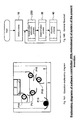
- Fig. 4 shows explanatory diagrams of a software constitution (a first embodiment) of a system according to the present invention
- Fig. 5 shows a flowchart showing an essential part of the software constitution (the first embodiment) in detail.
- reference numeral 2 designates an imaging region
- reference characters 2a to 2d designate an outline of the imaging region 2
- reference numeral 3 designates a dangerous source
- reference numeral 5 designates a warning region
- reference characters 5a to 5d designate an outline of the warning region
- reference numeral 6 designates a warning target region
- reference character P1 designates a person intruding into the warning region 5
- reference character P2 designates a person moving'toward the dangerous source 3 in the warning target region.
- the warning when the mobile object intrudes into the warning region 5 in the periphery of the dangerous source 3, the warning is immediately generated and when the mobile object intrudes into the warning target region 6 in the periphery of the warning region 5, the warning is generated only when the speed of the mobile object toward the dangerous source exceeds a predetermined value.
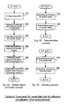
- the software shown in the general flowchart in Fig. 4B is carried out by the personal computer PC shown in Fig. 1 and includes an initial process (at step 10) , a mobile object arithmetic process (at step 20) , a determination process (at step 30) , and a warning process (at step 40) .
- a process for obtaining an initial image for a background difference process, a process for clearing various kinds of flags and the like are performed.
- the next mobile object arithmetic process at step 20
- a process for detecting the mobile object and calculating its number, a process for calculating the position of each mobile object, a process for calculating the speed of each mobile object toward the dangerous source and the like are performed.
- the next determination process at step 30
- a process for setting an intrusion flag at "1" when the mobile object is in the predetermined region, a process for setting a speed flag at "1" when the speed toward the dangerous source exceeds the predetermined value and the like are performed.
- next warning process (at step 40), a process for confirming the intrusion flag and the speed flag and outputting the warning signal when at least one of the flags is set at "1", and not outputting the warning signal when the flags are all at "0" are performed.
- Fig. 5A shows a detail of the mobile object arithmetic process (at step 20) .
- the current image is acquired at step 210.
- the mobile obj ect is figured out by a background difference method and its number is counted.
- the position of the mobile object is calculated. For example, coordinates at four corners of a rectangle surrounding the mobile object (referred to as a mobile object region hereinafter) are found.
- a feature amount of the mobile object is calculated from its color, area, configuration and the like. For example, a RGB value of a pixel extracted as the mobile object, an aspect ratio of the mobile object region and the like are found.
- the same ones are related to each other between the mobile object found by the mobile object arithmetic process at this time and the mobile object found by the mobile object arithmetic process at the previous time.
- that mobile object is regarded as the same one.
- that mobile object does not similar to any one, that mobile object is regarded as a new one.
- a moving amount toward the dangerous source in the Y direction in the drawing is found based on the related result and the speed is calculated. At this time, the speed of the new mobile object is set at "0".
- Fig. 5B shows a detail of the determination process (at step 30) .
- step 310 it is determined whether any mobile object is in the predetermined region (the warning region) or not and when it is, the intrusion flag set for each mobile object is set at "1". The intrusion is determined when any one of coordinates at the four corners of the mobile object region is within the predetermined region, for example.
- step 320 it is determined whether the speed of each mobile object toward the dangerous source exceeds the predetermine value or not and when it exceeds the value, the speed flag set for each mobile object is set at "1" .
- the threshold value of the speed determination is set at 2m/s, for example.
- Fig. 5C shows a detail of the warning process (at step 40).
- OR logical sum
- the warning signal is output and when it is "0", the warning signal is canceled.
- the predetermined warning is immediately generated.
- the warning is generated only when the person moves at the speed more than a certain value toward the dangerous source 3. Meanwhile, the warning is canceled when the person moves out of the warning region or the direction and the speed of the person in the warning target region does not exceed the predetermined value.
- the warning is generated regardless of the condition when the person is in the region 5 close to the dangerous source 3 in which the person could get into touch with the machine in a prompt action, and the warning is generated depending on the direction and the speed in the region 6 apart from the dangerous source 3.
- the person can be kept safe without lowering an operation rate of the machine.
- the warning region 5 is in the vicinity of the region just below the camera CA, the intrusion can be precisely detected.
- the precision as well as that in the warning region 5 is not required in the warning target region 6.
- Fig. 6 shows explanatory diagrams of a software constitution (a second embodiment) of a system according to the present invention
- Fig. 7 shows a flowchart showing an essential part of the software constitution (the second embodiment) in detail.
- reference numeral 2 designates an imaging region
- reference numeral 3 designates a dangerous source
- reference numeral 5 designates a warning region
- reference numeral 6 designates a warning target region
- reference numeral 7 designates a shielding object
- reference character P3 designates a person (mobile object). In this example, when all or a part of the object is lost in sight in the warning region 5, a warning is held up.
- Fig. 6B shows a general flowchart showing processes for implementing such intruding object monitoring function.
- Processes shown in this general flowchart comprises an initial process (at step 10), a mobile object arithmetic process (at step 20A) , a determination process (at step 30A) , and a warning process (step 40A).
- the same constituted part as in the process of the general flowchart in Fig. 4B is allotted to the same reference sign and its description is omitted.
- a process for detecting hiding is added.
- the next determination process in addition to the content of the determination process (at step 30) shown in Fig. 4B, a process for setting a hiding flag at "1" when the mobile object is hiding in the warning region is added.
- the next warning process in addition to the content of the warning process (step 40) shown in Fig. 4B, a process for holding up the warning when the hiding flag is "1" is added.
- Fig. 7A shows a detail of the mobile object arithmetic process (at step 20A).
- the same constituted part as in the process shown in Fig. 5A is allotted to the same reference sign and its description is omitted.
- step 250A in addition to the content at step 250 shown in Fig. 5A, a process for regarding the previous mobile object which does not correspond to any one of the mobile object at this time as being hiding is added.
- Fig. 7B shows a detail of the determination process (at step 30A).
- a process at step 330 is added.
- the hiding flag set for each mobile object is set at "1".
- the mobile obj ect is regarded as moved out of the viewing field and the process is not especially performed.
- Fig. 7C shows a detail of the warning process (at step 40A) .
- step 430 and step 440 are added. In other words, in this example, when the hiding flag is "1", the process is suspended (the warning is held up).
- Fig. 8 shows explanatory diagrams of a software constitution (a third embodiment) of a system according to the present invention
- Fig. 9 shows a flowchart showing the warning process of the software constitution (the third embodiment) in detail.
- a warning is held up when all or a part of an object is lost in sight in a warning region 5, the waning can be canceled only by a reset operation from the outside.
- Fig. 8B shows a general flowchart showing processes for implementing such intruding object monitoring function.
- the same constituted part as in the flowcharts shown in Fig. 4B and Fig. 68 is allotted to the same reference sign and its description is omitted.
- a process for canceling the warning when a reset is input is added.
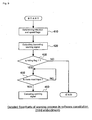
- Fig. 9 shows a detailed flowchart of the warning process (at step 40B) in the software constitution (the third embodiment) .
- the same constituted part as in Fig. 7C is allotted to the same reference sign and its description is omitted.
- the operation proceeds to a warning signal canceling process (at step 460).
- a warning signal is canceled.
- Fig. 10 shows explanatory diagrams of a software constitution (a fourth embodiment) of a system according to the present invention
- Fig. 11 shows a flowchart showing an essential part of the software constitution (the fourth embodiment) in detail.
- a warning is held up when the objects whose number exceeds a predetermined value intrude into a monitoring target region 2.
- reference numeral 2 designates a monitoring target region (a viewing field of a camera)
- reference numeral 3 designates a dangerous source
- reference numeral 5 designates a warning region
- reference numeral 6 designates a warning target region
- reference characters P4 to P9 designate people constituting the mobile objects.
- Fig. 10B shows a general flowchart of processes for implementing such intruding object monitoring function.
- the same constituted part as in the general flowcharts shown in Fig. 4A and Fig. 6B is allotted to the same reference sign and its description is omitted.
- a process for setting a mobile object number flag at "1" when the number of the mobile objects is more than a predetermined value is added.
- a warning process at step 40C
- the content in the warning process (at step 40B) shown in Fig. 8B is changed such that the warning is held up when the mobile object number flag is "1".
- Fig. 11A shows a detail of the mobile object arithmetic process (at step 20B).
- the same constituted part as in the process shown in Fig. 7A is allotted the same reference sign and its description is omitted.
- the mobile object number flag is set at "1" (at step 234).
- Fig. 11B shows a detail of the warning process (at step 40C) .
- the same constituted part as in the process shown in Fig. 9 is allotted the same reference sign and its description is omitted.
- step 430A it is determined whether the hiding flag or the mobile object number flag is "1" or not. When the hiding flag or the mobile object number flag is "1", the operation proceeds to reset waiting (a warning is held up).
- Fig. 12 shows explanatory diagrams of a software constitution (a fifth embodiment) of a system according to the present invention
- Fig. 13 shows a flowchart showing an essential part of the software constitution (the fifth embodiment) in detail.
- reference numeral 2 designates a monitoring target region (a viewing field of a camera)
- reference numeral 3 designates a dangerous source
- reference numeral 5 designates a warning region
- reference numeral 6 designates a warning target region
- reference signs P10 to P14 designate people constituting the mobile object.
- Fig. 12B shows a general flowchart showing processes for implementing such intruding object monitoring function.
- the same constituted part as in the process in Fig. 10B is allotted to the same sign and its description is omitted.
- a mobile object arithmetic process in a mobile object arithmetic process (at step 20C), the content of the mobile object arithmetic process (at step 20B) in Fig. 10B is changed to a content in which when the number of the mobile object is more than the predetermined value, following processes are skipped.
- a content of the warning process at step 40B is the same as that of the warning process (at step 40B) in Fig. 8B.
- Fig. 13A shows a detail of the mobile object arithmetic process (at step 20C). Referring to Fig. 13A, at step 232, when the number of mobile objects is more than a predetermined value, following process (at steps 240 to 260) are skipped.
- Fig. 13B shows a detail of the warning process (at step 40B). Referring to Fig. 13B, at step 430, when a hiding flag is "1", the operation proceeds to reset waiting (at step 450) .
- Fig. 14 shows explanatory diagrams of a software constitution (a sixth embodiment) of a system according to the present invention
- Fig. 15 shows flowcharts showing an essential part of the mobile object arithmetic process of the software constitution (the sixth embodiment) in detail.
- objects whose number is more than the predetermined value intrudes
- objects whose number is less than the predetermined value and which are closer to a dangerous source are monitored (including direction and speed).
- reference numeral 2 designates a monitoring target region (a viewing field of a camera)
- reference numeral 3 designates a dangerous source
- reference numeral 5 designates a warning region
- reference numeral 6 designates a warning target region
- reference character P15 designates a mobile object closest to the dangerous source 3
- reference character P16 designates a mobile object secondly closest to the dangerous source 3
- reference character 17 designates a mobile object thirdly closest to the dangerous source 3
- reference character P18 designates a mobile object fourthly closest to the dangerous source 3
- reference character P19 designates a mobile obj ect farthest from dangerous source 3.
- Fig. 14B shows a general flowchart showing processes for implementing such intruding object monitoring function.
- the same constituted part as in the process in Fig. 4B is allotted to the same sign and its description is omitted.
- a function of processing only the mobile object whose number is within the predetermined value and which are closer the dangerous source is added when the number of the mobile objects is more than the predetermined value.
- Fig. 15 shows a detail of the mobile object arithmetic process (at step 20D) in Fig. 14B.
- the same constituted part as in the process in Fig. 13A is allotted to the same sign and its description is omitted.
- a process is performed for calculating a distance between each object and the dangerous source, from a central coordinate of the dangerous source and a gravity point coordinate of the mobile object.
- a process is performed for calculating feature amounts of the mobile obj ects whose number is the predetermined value, which are selected in increasing order of the distance.
- the calculation of the feature amount is the same as the content at step 240 shown in Fig. 5A.
- a process is performed for relating the mobile objects whose number is the predetermined value, which are selected in increasing order of the distance to each other. In addition, this method is the same as the content at step 250 shown in Fig. 5A.
- the speed of the mobile objects whose number is the predetermined value, which are selected in increasing order of the distance, toward the dangerous source is calculated. The calculation of the speed is the same as the content at step 260 shown in Fig. 5A.
- the function (processing time or recognition precision) of the intruding object monitoring system can be maintained in only the process of monitoring the objects whose number is within the predetermined value.
- the intruding obj ect can be monitored with high reliability with only one camera.
Landscapes
- Engineering & Computer Science (AREA)
- General Engineering & Computer Science (AREA)
- Mechanical Engineering (AREA)
- Alarm Systems (AREA)
- Burglar Alarm Systems (AREA)
- Image Analysis (AREA)
- Emergency Alarm Devices (AREA)
- Numerical Control (AREA)
- Manipulator (AREA)
- Image Processing (AREA)
- Closed-Circuit Television Systems (AREA)
Abstract
Description
Claims (10)
- An intruding object monitoring system comprising:wherein a mounting position of the camera is determined so that the dangerous source is shown at a peripheral part of a viewing field of the camera.a camera mounted on a position so as to look down a monitoring target region including a dangerous source; andan information processing apparatus performing information processes for monitoring an intruding obj ect based on a monitoring target region image taken by the camera,
- An intruding object monitoring system comprising:wherein the dangerous source can be set only at a peripheral part of a viewing field of the camera.a camera mounted on a position so as to look down a monitoring target region including a dangerous source; andan information processing apparatus performing information processes for monitoring an intruding obj ect based on a monitoring target region image taken by the camera,
- The intruding object monitoring system according to claim 1 or 2, wherein the information processes for monitoring the intruding object performed in the information processing apparatus comprises a process for determining that a mobile object intrudes into a warning region set in the vicinity of the dangerous source, by comparing a mobile object position in the monitoring target region image to a warning region position in the monitoring target region image on an image.
- The intruding object monitoring system according to claim 1, wherein the information processes for monitoring the intruding object performed in the information processing apparatus comprises a process for immediately generating a warning in a case where a mobile object intrudes into a warning region existing in the vicinity of the dangerous source, while for generating a warning only when speed of the mobile object toward the dangerous source exceeds a predetermined value in a case where the mobile obj ect intrudes into the warning target region existing in the vicinity of the warning region.
- The intruding obj ect monitoring system according to claim 2, wherein the information processes for monitoring the intruding object performed in the information processing apparatus comprises a process for immediately generating a warning in a case where a mobile object intrudes into a warning region existing in the vicinity of the dangerous source, while for generating a warning only when speed of the mobile object toward the dangerous source exceeds a predetermined value in a case where the mobile obj ect intrudes into the warning target region existing in the vicinity of the warning region.
- The intruding object monitoring system according to claim 4 or 5, wherein the information process for monitoring the intruding object performed in the information processing apparatus comprises a process for continuously generating the warning until the mobile object which intruded into the warning region existing in the vicinity of the dangerous source moves out of the warning region, while for holding up the warning when at least one part of the mobile object is lost in sight in the warning region.
- The intruding object monitoring system according to claim 6, wherein the information processes for monitoring the intruding object performed in the information processing apparatus comprises a process for allowing a reset of the warning which was held up when at least one part of the mobile object is lost in sight in the warning region, only by a manual resetting operation.
- The intruding object monitoring system according to claim 4 or 5, wherein the information processes for monitoring the intruding object performed in the information processing apparatus comprises a process for immediately generating the warning and then holding up the warning when the mobile obj ects whose number is more than a predetermined value intrude into the monitoring target region.
- The intruding object monitoring system according to claim 4 or 5, wherein the information processes for monitoring the intruding object performed in the information processing apparatus comprises a process for monitoring only the mobile objects existing in the warning region when the total number of the mobile objects existing in the warning region and the number of the mobile objects existing in the warning target region is more than a predetermined value.
- The intruding object monitoring system according to claim 4 or 5, wherein the information processes for monitoring the intruding object performed in the information processing apparatus comprises a process for monitoring only the mobile objects whose number is a predetermined value and which are selected in increasing order of a distance from the dangerous source when the mobile objects whose number is more than the predetermined value intrude into the monitoring target region.
Applications Claiming Priority (2)
| Application Number | Priority Date | Filing Date | Title |
|---|---|---|---|
| JP2003068794A JP4066168B2 (en) | 2003-03-13 | 2003-03-13 | Intruder monitoring device |
| JP2003068794 | 2003-03-13 |
Publications (3)
| Publication Number | Publication Date |
|---|---|
| EP1457730A2 true EP1457730A2 (en) | 2004-09-15 |
| EP1457730A3 EP1457730A3 (en) | 2005-06-15 |
| EP1457730B1 EP1457730B1 (en) | 2010-09-29 |
Family
ID=32767968
Family Applications (1)
| Application Number | Title | Priority Date | Filing Date |
|---|---|---|---|
| EP04004449A Expired - Lifetime EP1457730B1 (en) | 2003-03-13 | 2004-02-26 | Intruding object monitoring system |
Country Status (5)
| Country | Link |
|---|---|
| US (1) | US20040227816A1 (en) |
| EP (1) | EP1457730B1 (en) |
| JP (1) | JP4066168B2 (en) |
| CN (1) | CN100337254C (en) |
| DE (1) | DE602004029304D1 (en) |
Cited By (9)
| Publication number | Priority date | Publication date | Assignee | Title |
|---|---|---|---|---|
| WO2007085330A1 (en) * | 2006-01-30 | 2007-08-02 | Abb Ab | A method and a system for supervising a work area including an industrial robot |
| EP2053538A1 (en) * | 2007-10-25 | 2009-04-29 | Sick Ag | Securing a surveillance area and visual support for automatic processing |
| WO2013093163A1 (en) * | 2011-12-23 | 2013-06-27 | Universidad De Extremadura | System for active and immediate detection and prevention of risks in industrial machinery |
| US8731276B2 (en) | 2009-12-28 | 2014-05-20 | Panasonic Corporation | Motion space presentation device and motion space presentation method |
| JP2014148027A (en) * | 2013-02-04 | 2014-08-21 | Seiko Epson Corp | Warning device |
| US9333652B2 (en) | 2013-11-11 | 2016-05-10 | Industrial Technology Research Institute | Safety monitoring system for human-machine symbiosis and method using the same |
| US10384345B2 (en) | 2016-07-27 | 2019-08-20 | Fanuc Corporation | Safety management method and safety management system |
| AT16611U1 (en) * | 2017-12-06 | 2020-02-15 | Wide Automation S R L | security system |
| US10618170B2 (en) | 2017-02-17 | 2020-04-14 | Fanuc Corporation | Robot system |
Families Citing this family (38)
| Publication number | Priority date | Publication date | Assignee | Title |
|---|---|---|---|---|
| KR100725544B1 (en) * | 2006-05-01 | 2007-06-08 | 삼성전자주식회사 | A mobile communication terminal and a method for blocking harmful information thereof |
| DE102006048166A1 (en) * | 2006-08-02 | 2008-02-07 | Daimler Ag | Method for observing a person in an industrial environment |
| JP2008165341A (en) * | 2006-12-27 | 2008-07-17 | Giken Torasutemu Kk | Person movement path recognition apparatus |
| JP5377837B2 (en) * | 2007-05-31 | 2013-12-25 | 株式会社キーエンス | Photoelectric sensor |
| JP5432983B2 (en) * | 2009-03-09 | 2014-03-05 | パナソニック株式会社 | Entrance / exit detection device, monitoring device, and entrance / exit detection method |
| TWI471825B (en) * | 2010-07-27 | 2015-02-01 | Hon Hai Prec Ind Co Ltd | System and method for managing security of a roof |
| JP2013012836A (en) * | 2011-06-28 | 2013-01-17 | Nifco Inc | Data recording control device and data recording device |
| KR101207197B1 (en) | 2011-08-30 | 2012-12-03 | 주식회사 아이디스 | Digital image monitoring apparatus through setting virtual tripzone and the method thereof |
| JP5378479B2 (en) * | 2011-10-31 | 2013-12-25 | 株式会社キーエンス | Photoelectric sensor and setting method thereof |
| CN103192414B (en) * | 2012-01-06 | 2015-06-03 | 沈阳新松机器人自动化股份有限公司 | Robot anti-collision protection device and method based on machine vision |
| DE112012005650B4 (en) * | 2012-01-13 | 2018-01-25 | Mitsubishi Electric Corporation | Risk measurement system |
| JP5874412B2 (en) * | 2012-01-30 | 2016-03-02 | セイコーエプソン株式会社 | Robot, approach detection method |
| JP5924134B2 (en) | 2012-05-30 | 2016-05-25 | セイコーエプソン株式会社 | Intrusion detection device, robot system, intrusion detection method, and intrusion detection program |
| JP6018821B2 (en) * | 2012-07-09 | 2016-11-02 | 東京エレクトロン株式会社 | CLEAN ROOM MONITORING DEVICE AND CLEAN ROOM MONITORING METHOD |
| JP6123307B2 (en) | 2013-01-23 | 2017-05-10 | 株式会社デンソーウェーブ | Surveillance system and method for monitoring the intrusion of an object around a robot |
| JP2015131375A (en) * | 2014-01-15 | 2015-07-23 | セイコーエプソン株式会社 | Robot, robot system, robot control device, and robot control method |
| JP6402469B2 (en) | 2014-04-04 | 2018-10-10 | 富士電機株式会社 | Safety control device and safety control system |
| JP6034892B2 (en) | 2015-01-27 | 2016-11-30 | ファナック株式会社 | A robot system in which the brightness of the robot mount changes |
| JP6177837B2 (en) * | 2015-06-30 | 2017-08-09 | ファナック株式会社 | Robot system using visual sensor |
| US9842485B2 (en) * | 2015-08-25 | 2017-12-12 | Honeywell International Inc. | Prognosticating panic situations and pre-set panic notification in a security system |
| JP6088605B1 (en) | 2015-08-31 | 2017-03-01 | ファナック株式会社 | Robot system using visual sensor |
| JP6572092B2 (en) * | 2015-10-21 | 2019-09-04 | ファナック株式会社 | A moving body system using a visual sensor |
| US10945361B2 (en) * | 2016-02-17 | 2021-03-09 | Fuji Corporation | Production line safety system |
| DE102016007519A1 (en) * | 2016-06-20 | 2017-12-21 | Kuka Roboter Gmbh | Monitoring a system with at least one robot |
| DE102016007520A1 (en) * | 2016-06-20 | 2017-12-21 | Kuka Roboter Gmbh | Monitoring a robot arrangement |
| CN106003047B (en) * | 2016-06-28 | 2019-01-22 | 北京光年无限科技有限公司 | A kind of danger early warning method and apparatus towards intelligent robot |
| JP6416980B1 (en) | 2017-05-17 | 2018-10-31 | ファナック株式会社 | Monitoring device for monitoring a spatial area obtained by dividing a monitoring area |
| DE102017221305B4 (en) * | 2017-11-23 | 2025-08-07 | Robert Bosch Gmbh | Method for operating a collaborative robot with a sensor on the head of a person and computer program |
| CN111220202A (en) * | 2018-11-23 | 2020-06-02 | 中国科学院大连化学物理研究所 | Dangerous chemical solution safety early warning remote monitoring system and method based on Internet of things |
| US11726018B2 (en) * | 2018-11-30 | 2023-08-15 | Illinois Tool Works Inc. | Safety system interfaces and material testing systems including safety system interfaces |
| US11879871B2 (en) * | 2018-11-30 | 2024-01-23 | Illinois Tool Works Inc. | Safety systems requiring intentional function activation and material testing systems including safety systems requiring intentional function activation |
| JP2020095617A (en) * | 2018-12-14 | 2020-06-18 | コニカミノルタ株式会社 | Safety management support system and control program |
| CN111310556A (en) * | 2019-12-20 | 2020-06-19 | 山东汇佳软件科技股份有限公司 | Drowning prevention safety supervision system based on primary and middle school student area and monitoring method thereof |
| JP7122439B2 (en) * | 2020-07-06 | 2022-08-19 | 株式会社タクマ | Garbage pit fall alarm device, garbage pit fall alarm method and garbage pit fall alarm program |
| JP7527884B2 (en) * | 2020-07-31 | 2024-08-05 | 株式会社東芝 | Attention calling system, attention calling method and program |
| CN112333355A (en) * | 2020-09-09 | 2021-02-05 | 北京潞电电气设备有限公司 | A tunnel inspection system |
| CN114299391A (en) * | 2021-12-28 | 2022-04-08 | 联想(北京)有限公司 | An information processing method, device and electronic device |
| US12430916B2 (en) * | 2022-01-19 | 2025-09-30 | Target Brands, Inc. | Safety compliance system and method |
Family Cites Families (9)
| Publication number | Priority date | Publication date | Assignee | Title |
|---|---|---|---|---|
| JPH05261692A (en) * | 1992-03-17 | 1993-10-12 | Fujitsu Ltd | Working environment monitoring device for robot |
| US6167143A (en) * | 1993-05-03 | 2000-12-26 | U.S. Philips Corporation | Monitoring system |
| CN1168185C (en) * | 1999-12-20 | 2004-09-22 | 阿斯莫株式会社 | Rectifier forming plate, rectifier, motor with rectifier and manufacture thereof |
| DE10000287B4 (en) * | 2000-01-07 | 2004-02-12 | Leuze Lumiflex Gmbh + Co. Kg | Device and method for monitoring a detection area on a work equipment |
| US6829371B1 (en) * | 2000-04-29 | 2004-12-07 | Cognex Corporation | Auto-setup of a video safety curtain system |
| US6504470B2 (en) * | 2000-05-19 | 2003-01-07 | Nextgenid, Ltd. | Access control method and apparatus for members and guests |
| US7200246B2 (en) * | 2000-11-17 | 2007-04-03 | Honeywell International Inc. | Object detection |
| DE10152543A1 (en) * | 2001-10-24 | 2003-05-08 | Sick Ag | Method and device for controlling a safety-relevant function of a machine |
| DE10327388C5 (en) * | 2003-06-18 | 2011-12-08 | Leuze Lumiflex Gmbh + Co. Kg | guard |
-
2003
- 2003-03-13 JP JP2003068794A patent/JP4066168B2/en not_active Expired - Fee Related
-
2004
- 2004-02-26 EP EP04004449A patent/EP1457730B1/en not_active Expired - Lifetime
- 2004-02-26 DE DE602004029304T patent/DE602004029304D1/en not_active Expired - Lifetime
- 2004-03-10 US US10/796,300 patent/US20040227816A1/en not_active Abandoned
- 2004-03-12 CN CNB2004100287402A patent/CN100337254C/en not_active Expired - Fee Related
Cited By (10)
| Publication number | Priority date | Publication date | Assignee | Title |
|---|---|---|---|---|
| WO2007085330A1 (en) * | 2006-01-30 | 2007-08-02 | Abb Ab | A method and a system for supervising a work area including an industrial robot |
| EP2053538A1 (en) * | 2007-10-25 | 2009-04-29 | Sick Ag | Securing a surveillance area and visual support for automatic processing |
| US8731276B2 (en) | 2009-12-28 | 2014-05-20 | Panasonic Corporation | Motion space presentation device and motion space presentation method |
| WO2013093163A1 (en) * | 2011-12-23 | 2013-06-27 | Universidad De Extremadura | System for active and immediate detection and prevention of risks in industrial machinery |
| ES2421285A1 (en) * | 2011-12-23 | 2013-08-30 | Universidad De Extremadura | System for active and immediate detection and prevention of risks in industrial machinery |
| JP2014148027A (en) * | 2013-02-04 | 2014-08-21 | Seiko Epson Corp | Warning device |
| US9333652B2 (en) | 2013-11-11 | 2016-05-10 | Industrial Technology Research Institute | Safety monitoring system for human-machine symbiosis and method using the same |
| US10384345B2 (en) | 2016-07-27 | 2019-08-20 | Fanuc Corporation | Safety management method and safety management system |
| US10618170B2 (en) | 2017-02-17 | 2020-04-14 | Fanuc Corporation | Robot system |
| AT16611U1 (en) * | 2017-12-06 | 2020-02-15 | Wide Automation S R L | security system |
Also Published As
| Publication number | Publication date |
|---|---|
| JP4066168B2 (en) | 2008-03-26 |
| US20040227816A1 (en) | 2004-11-18 |
| CN100337254C (en) | 2007-09-12 |
| EP1457730B1 (en) | 2010-09-29 |
| JP2004276154A (en) | 2004-10-07 |
| DE602004029304D1 (en) | 2010-11-11 |
| EP1457730A3 (en) | 2005-06-15 |
| CN1538355A (en) | 2004-10-20 |
Similar Documents
| Publication | Publication Date | Title |
|---|---|---|
| EP1457730B1 (en) | Intruding object monitoring system | |
| US10379513B2 (en) | Monitoring system, monitoring device, and monitoring method | |
| KR102786033B1 (en) | Monitoring device, industrial equipment, monitoring method, and computer program | |
| JP6360105B2 (en) | Robot system | |
| KR101742634B1 (en) | Device and method for monitoring moving entity | |
| JP7043968B2 (en) | Monitoring system and monitoring method | |
| US9073483B2 (en) | Vehicle surroundings monitoring device | |
| CN109564382B (en) | Shooting device and shooting method | |
| JP6722051B2 (en) | Object detection device and object detection method | |
| KR20140009148A (en) | Work machine peripheral monitoring device | |
| JP2021139283A (en) | Detection system | |
| KR102815590B1 (en) | safety equipment wearing monitoring system for workers and dangerous situation warning system at work site based on artificial intelligence deep learning | |
| KR20230101505A (en) | The around monitoring apparatus ofo the image base | |
| JP2020142903A (en) | Image processing apparatus and control program | |
| JP4171501B2 (en) | Vehicle periphery monitoring device | |
| JPH05261692A (en) | Working environment monitoring device for robot | |
| CN111113374A (en) | Robot system | |
| US20250244741A1 (en) | Real-Time Collision Detection and Illuminated Guidance System Using Computer Vision | |
| JP2020021110A (en) | Warning system, warning control device, and warning method | |
| JP6806845B2 (en) | Robot system and robot control method | |
| DE102014209337A1 (en) | System and method for detecting a hazardous area | |
| US10204276B2 (en) | Imaging device, method and recording medium for capturing a three-dimensional field of view | |
| RU2270162C2 (en) | Method to increase safety of operation of load-lifting crane | |
| KR20220161611A (en) | AVM system with point-of-view function | |
| JP7581576B2 (en) | How to operate an overhead crane equipped with a human detection system |
Legal Events
| Date | Code | Title | Description |
|---|---|---|---|
| PUAI | Public reference made under article 153(3) epc to a published international application that has entered the european phase |
Free format text: ORIGINAL CODE: 0009012 |
|
| AK | Designated contracting states |
Kind code of ref document: A2 Designated state(s): AT BE BG CH CY CZ DE DK EE ES FI FR GB GR HU IE IT LI LU MC NL PT RO SE SI SK TR |
|
| AX | Request for extension of the european patent |
Extension state: AL LT LV MK |
|
| RIN1 | Information on inventor provided before grant (corrected) |
Inventor name: AKAGI, TETSUYAC/O OMRON CORPORATION801, Inventor name: UEKI, JUNICHIROC/O OMRON CORPORATION801, Inventor name: IIDA, TOYOOC/O OMRON CORPORATION801, Inventor name: SATO, MASANORIC/O OMRON CORPORATION801, |
|
| PUAL | Search report despatched |
Free format text: ORIGINAL CODE: 0009013 |
|
| AK | Designated contracting states |
Kind code of ref document: A3 Designated state(s): AT BE BG CH CY CZ DE DK EE ES FI FR GB GR HU IE IT LI LU MC NL PT RO SE SI SK TR |
|
| AX | Request for extension of the european patent |
Extension state: AL LT LV MK |
|
| 17P | Request for examination filed |
Effective date: 20051014 |
|
| AKX | Designation fees paid |
Designated state(s): DE FR GB IT |
|
| 17Q | First examination report despatched |
Effective date: 20070220 |
|
| GRAP | Despatch of communication of intention to grant a patent |
Free format text: ORIGINAL CODE: EPIDOSNIGR1 |
|
| GRAS | Grant fee paid |
Free format text: ORIGINAL CODE: EPIDOSNIGR3 |
|
| GRAA | (expected) grant |
Free format text: ORIGINAL CODE: 0009210 |
|
| AK | Designated contracting states |
Kind code of ref document: B1 Designated state(s): DE FR GB IT |
|
| REG | Reference to a national code |
Ref country code: GB Ref legal event code: FG4D |
|
| REF | Corresponds to: |
Ref document number: 602004029304 Country of ref document: DE Date of ref document: 20101111 Kind code of ref document: P |
|
| PLBI | Opposition filed |
Free format text: ORIGINAL CODE: 0009260 |
|
| 26 | Opposition filed |
Opponent name: LEUZE ELECTRONIC GMBH + CO. KG Effective date: 20110614 |
|
| PLAX | Notice of opposition and request to file observation + time limit sent |
Free format text: ORIGINAL CODE: EPIDOSNOBS2 |
|
| REG | Reference to a national code |
Ref country code: DE Ref legal event code: R026 Ref document number: 602004029304 Country of ref document: DE Effective date: 20110614 |
|
| PLBB | Reply of patent proprietor to notice(s) of opposition received |
Free format text: ORIGINAL CODE: EPIDOSNOBS3 |
|
| PLCK | Communication despatched that opposition was rejected |
Free format text: ORIGINAL CODE: EPIDOSNREJ1 |
|
| PLBN | Opposition rejected |
Free format text: ORIGINAL CODE: 0009273 |
|
| STAA | Information on the status of an ep patent application or granted ep patent |
Free format text: STATUS: OPPOSITION REJECTED |
|
| REG | Reference to a national code |
Ref country code: DE Ref legal event code: R082 Ref document number: 602004029304 Country of ref document: DE Representative=s name: KILIAN KILIAN & PARTNER, DE Ref country code: DE Ref legal event code: R082 Ref document number: 602004029304 Country of ref document: DE Representative=s name: KILIAN KILIAN & PARTNER MBB PATENTANWAELTE, DE |
|
| 27O | Opposition rejected |
Effective date: 20121015 |
|
| REG | Reference to a national code |
Ref country code: DE Ref legal event code: R100 Ref document number: 602004029304 Country of ref document: DE Effective date: 20121015 |
|
| REG | Reference to a national code |
Ref country code: FR Ref legal event code: PLFP Year of fee payment: 13 |
|
| REG | Reference to a national code |
Ref country code: FR Ref legal event code: PLFP Year of fee payment: 14 |
|
| REG | Reference to a national code |
Ref country code: FR Ref legal event code: PLFP Year of fee payment: 15 |
|
| PGFP | Annual fee paid to national office [announced via postgrant information from national office to epo] |
Ref country code: IT Payment date: 20190221 Year of fee payment: 19 |
|
| PGFP | Annual fee paid to national office [announced via postgrant information from national office to epo] |
Ref country code: DE Payment date: 20200211 Year of fee payment: 17 |
|
| PGFP | Annual fee paid to national office [announced via postgrant information from national office to epo] |
Ref country code: FR Payment date: 20200113 Year of fee payment: 17 |
|
| GBPC | Gb: european patent ceased through non-payment of renewal fee |
Effective date: 20200226 |
|
| PG25 | Lapsed in a contracting state [announced via postgrant information from national office to epo] |
Ref country code: GB Free format text: LAPSE BECAUSE OF NON-PAYMENT OF DUE FEES Effective date: 20200226 |
|
| REG | Reference to a national code |
Ref country code: DE Ref legal event code: R119 Ref document number: 602004029304 Country of ref document: DE |
|
| PG25 | Lapsed in a contracting state [announced via postgrant information from national office to epo] |
Ref country code: IT Free format text: LAPSE BECAUSE OF NON-PAYMENT OF DUE FEES Effective date: 20200226 |
|
| PG25 | Lapsed in a contracting state [announced via postgrant information from national office to epo] |
Ref country code: FR Free format text: LAPSE BECAUSE OF NON-PAYMENT OF DUE FEES Effective date: 20210228 Ref country code: DE Free format text: LAPSE BECAUSE OF NON-PAYMENT OF DUE FEES Effective date: 20210901 |