EP1457696A1 - Universal joint with friction and bearing cup retainer - Google Patents
Universal joint with friction and bearing cup retainer Download PDFInfo
- Publication number
- EP1457696A1 EP1457696A1 EP04001517A EP04001517A EP1457696A1 EP 1457696 A1 EP1457696 A1 EP 1457696A1 EP 04001517 A EP04001517 A EP 04001517A EP 04001517 A EP04001517 A EP 04001517A EP 1457696 A1 EP1457696 A1 EP 1457696A1
- Authority
- EP
- European Patent Office
- Prior art keywords
- trunnion
- universal joint
- prong
- lubricant passage
- bearing
- Prior art date
- Legal status (The legal status is an assumption and is not a legal conclusion. Google has not performed a legal analysis and makes no representation as to the accuracy of the status listed.)
- Granted
Links
Images




Classifications
-
- C—CHEMISTRY; METALLURGY
- C10—PETROLEUM, GAS OR COKE INDUSTRIES; TECHNICAL GASES CONTAINING CARBON MONOXIDE; FUELS; LUBRICANTS; PEAT
- C10G—CRACKING HYDROCARBON OILS; PRODUCTION OF LIQUID HYDROCARBON MIXTURES, e.g. BY DESTRUCTIVE HYDROGENATION, OLIGOMERISATION, POLYMERISATION; RECOVERY OF HYDROCARBON OILS FROM OIL-SHALE, OIL-SAND, OR GASES; REFINING MIXTURES MAINLY CONSISTING OF HYDROCARBONS; REFORMING OF NAPHTHA; MINERAL WAXES
- C10G3/00—Production of liquid hydrocarbon mixtures from oxygen-containing organic materials, e.g. fatty oils, fatty acids
-
- F—MECHANICAL ENGINEERING; LIGHTING; HEATING; WEAPONS; BLASTING
- F16—ENGINEERING ELEMENTS AND UNITS; GENERAL MEASURES FOR PRODUCING AND MAINTAINING EFFECTIVE FUNCTIONING OF MACHINES OR INSTALLATIONS; THERMAL INSULATION IN GENERAL
- F16D—COUPLINGS FOR TRANSMITTING ROTATION; CLUTCHES; BRAKES
- F16D3/00—Yielding couplings, i.e. with means permitting movement between the connected parts during the drive
- F16D3/16—Universal joints in which flexibility is produced by means of pivots or sliding or rolling connecting parts
- F16D3/26—Hooke's joints or other joints with an equivalent intermediate member to which each coupling part is pivotally or slidably connected
- F16D3/38—Hooke's joints or other joints with an equivalent intermediate member to which each coupling part is pivotally or slidably connected with a single intermediate member with trunnions or bearings arranged on two axes perpendicular to one another
- F16D3/40—Hooke's joints or other joints with an equivalent intermediate member to which each coupling part is pivotally or slidably connected with a single intermediate member with trunnions or bearings arranged on two axes perpendicular to one another with intermediate member provided with two pairs of outwardly-directed trunnions on intersecting axes
- F16D3/41—Hooke's joints or other joints with an equivalent intermediate member to which each coupling part is pivotally or slidably connected with a single intermediate member with trunnions or bearings arranged on two axes perpendicular to one another with intermediate member provided with two pairs of outwardly-directed trunnions on intersecting axes with ball or roller bearings
-
- F—MECHANICAL ENGINEERING; LIGHTING; HEATING; WEAPONS; BLASTING
- F16—ENGINEERING ELEMENTS AND UNITS; GENERAL MEASURES FOR PRODUCING AND MAINTAINING EFFECTIVE FUNCTIONING OF MACHINES OR INSTALLATIONS; THERMAL INSULATION IN GENERAL
- F16C—SHAFTS; FLEXIBLE SHAFTS; ELEMENTS OR CRANKSHAFT MECHANISMS; ROTARY BODIES OTHER THAN GEARING ELEMENTS; BEARINGS
- F16C17/00—Sliding-contact bearings for exclusively rotary movement
- F16C17/04—Sliding-contact bearings for exclusively rotary movement for axial load only
- F16C17/08—Sliding-contact bearings for exclusively rotary movement for axial load only for supporting the end face of a shaft or other member, e.g. footstep bearings
-
- F—MECHANICAL ENGINEERING; LIGHTING; HEATING; WEAPONS; BLASTING
- F16—ENGINEERING ELEMENTS AND UNITS; GENERAL MEASURES FOR PRODUCING AND MAINTAINING EFFECTIVE FUNCTIONING OF MACHINES OR INSTALLATIONS; THERMAL INSULATION IN GENERAL
- F16C—SHAFTS; FLEXIBLE SHAFTS; ELEMENTS OR CRANKSHAFT MECHANISMS; ROTARY BODIES OTHER THAN GEARING ELEMENTS; BEARINGS
- F16C21/00—Combinations of sliding-contact bearings with ball or roller bearings, for exclusively rotary movement
- F16C21/005—Combinations of sliding-contact bearings with ball or roller bearings, for exclusively rotary movement the external zone of a bearing with rolling members, e.g. needles, being cup-shaped, with or without a separate thrust-bearing disc or ring, e.g. for universal joints
-
- F—MECHANICAL ENGINEERING; LIGHTING; HEATING; WEAPONS; BLASTING
- F16—ENGINEERING ELEMENTS AND UNITS; GENERAL MEASURES FOR PRODUCING AND MAINTAINING EFFECTIVE FUNCTIONING OF MACHINES OR INSTALLATIONS; THERMAL INSULATION IN GENERAL
- F16D—COUPLINGS FOR TRANSMITTING ROTATION; CLUTCHES; BRAKES
- F16D3/00—Yielding couplings, i.e. with means permitting movement between the connected parts during the drive
- F16D3/16—Universal joints in which flexibility is produced by means of pivots or sliding or rolling connecting parts
- F16D3/26—Hooke's joints or other joints with an equivalent intermediate member to which each coupling part is pivotally or slidably connected
- F16D3/38—Hooke's joints or other joints with an equivalent intermediate member to which each coupling part is pivotally or slidably connected with a single intermediate member with trunnions or bearings arranged on two axes perpendicular to one another
- F16D3/382—Hooke's joints or other joints with an equivalent intermediate member to which each coupling part is pivotally or slidably connected with a single intermediate member with trunnions or bearings arranged on two axes perpendicular to one another constructional details of other than the intermediate member
- F16D3/385—Bearing cup; Bearing construction; Bearing seal; Mounting of bearing on the intermediate member
-
- F—MECHANICAL ENGINEERING; LIGHTING; HEATING; WEAPONS; BLASTING
- F16—ENGINEERING ELEMENTS AND UNITS; GENERAL MEASURES FOR PRODUCING AND MAINTAINING EFFECTIVE FUNCTIONING OF MACHINES OR INSTALLATIONS; THERMAL INSULATION IN GENERAL
- F16C—SHAFTS; FLEXIBLE SHAFTS; ELEMENTS OR CRANKSHAFT MECHANISMS; ROTARY BODIES OTHER THAN GEARING ELEMENTS; BEARINGS
- F16C2361/00—Apparatus or articles in engineering in general
- F16C2361/41—Couplings
-
- F—MECHANICAL ENGINEERING; LIGHTING; HEATING; WEAPONS; BLASTING
- F16—ENGINEERING ELEMENTS AND UNITS; GENERAL MEASURES FOR PRODUCING AND MAINTAINING EFFECTIVE FUNCTIONING OF MACHINES OR INSTALLATIONS; THERMAL INSULATION IN GENERAL
- F16D—COUPLINGS FOR TRANSMITTING ROTATION; CLUTCHES; BRAKES
- F16D2300/00—Special features for couplings or clutches
- F16D2300/06—Lubrication details not provided for in group F16D13/74
-
- Y—GENERAL TAGGING OF NEW TECHNOLOGICAL DEVELOPMENTS; GENERAL TAGGING OF CROSS-SECTIONAL TECHNOLOGIES SPANNING OVER SEVERAL SECTIONS OF THE IPC; TECHNICAL SUBJECTS COVERED BY FORMER USPC CROSS-REFERENCE ART COLLECTIONS [XRACs] AND DIGESTS
- Y02—TECHNOLOGIES OR APPLICATIONS FOR MITIGATION OR ADAPTATION AGAINST CLIMATE CHANGE
- Y02P—CLIMATE CHANGE MITIGATION TECHNOLOGIES IN THE PRODUCTION OR PROCESSING OF GOODS
- Y02P30/00—Technologies relating to oil refining and petrochemical industry
- Y02P30/20—Technologies relating to oil refining and petrochemical industry using bio-feedstock
Definitions
- the present invention generally relates to a universal joint for use in a driveline of a motor vehicle. More specifically, the present invention pertains to a universal joint equipped with a mechanism for securing a bearing cup assembly to a cruciform trunnion.
- universal joints are used in motor vehicle driveline applications for interconnecting a pair of rotary shafts and permitting changes in angularity therebetween.
- Many conventional universal joints include a pair of bifurcated yokes which are secured to the rotary shafts.
- the bifurcated yokes are interconnected by a spider or a cruciform for rotation about independent axes.
- the cruciform includes four orthogonal trunnions with each opposing pair of axially aligned trunnions mounted in a pair of aligned bores formed in the bifurcated yokes.
- a bearing cup is secured in each bore and a bearing assembly is retained in the bearing cup such that each yoke is supported for pivotal movement relative to one of the pairs of trunnions.
- a thrust washer between the trunnion and the bearing cup to absorb the radially-directed thrust forces which may occur therebetween.
- each bearing assembly, thrust washer and bearing cup are positioned on a trunnion but not positively retained thereto.
- the bearing cup and bearing assembly may be accidentally disrupted and separated from the trunnion. Gravitational forces may also cause separation of the components during the assembly process. Possible bearing contamination and loss of productivity may result.
- extraneous straps, nets or other packaging are used to retain the bearing cup assemblies in place during shipping and handling. These straps must be removed and discarded by the end user requiring expense of time and cost. Accordingly, it would be advantageous to provide a universal joint having bearing cup assemblies which are retained on the trunnions without the use of external discardable devices.
- the present invention is directed to a universal joint for interconnecting a pair of rotating shafts.
- the universal joint includes a pair of bifurcated yokes interconnected by a cruciform.
- the cruciform includes four orthogonal trunnions each including a lubricant passage.
- a thrust washer engages an inner surface of the lubricant passage to retain a bearing assembly on each trunnion.
- the present invention is directed to a universal joint of the type used in motor vehicle driveline applications for interconnecting rotating shafts in a manner permitting changes in angularity therebetween.
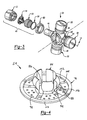
- a universal joint 10 is shown connecting a first shaft 12 to a second shaft 14.
- universal joint 10 includes a first yoke 16 attached to an end of first shaft 12, a second yoke 18 attached to an end of second shaft 14 and a cruciform 20 interconnecting first yoke 16 to second yoke 18.
- the first yoke 16 is bifurcated and includes a pair of laterally-spaced legs 22 which are preferably symmetrical with respect to the rotary axis of first shaft 12, as denoted by construction line "A".
- Legs 22 include an inboard surface 24 and an outboard surface 26 with a journal 27 extending therebetween.
- Apertures 28 are formed by coupling a pair of end caps 30 to legs 22 via fasteners 31. End caps 30 cooperate with journals 27 to complete apertures 28. Apertures 28 are aligned on a first trunnion axis, as denoted by construction line "Y", which passes through and is orthogonal with respect to rotary axis "A" of first shaft 12.
- Second yoke 18 is bifurcated and includes a pair of laterally-spaced legs 32 which are preferably symmetrical with respect to the rotary axis of second shaft 14, as denoted by construction line "B".
- Legs 32 include an inboard surface 34 and an outboard surface 36 with an aperture 38 extending therebetween.
- Apertures 38 are aligned on a second trunnion axis, as denoted by construction line “Z”, which passes through and is orthogonal with respect to rotary axis "B" of second shaft 14.
- Apertures 38 are throughbores which include an annular groove 40 formed between the inboard surface 34 and the outboard surface 36.
- the shape and dimensions of apertures 28 and 38 may either be identical or different depending on the particular dimensions of cruciform 20 used therewith.
- the annular ring grooves 40 may be formed by machining, casting or by similar technique.
- cruciform 20 includes a central hub 42 from which a pair of first trunnions 44 and a pair of second trunnions 46 extend.
- First trunnions 44 are orthogonal with respect to second trunnions 46.
- First trunnions 44 are adapted for insertion into apertures 28 in legs 22 of first yoke 16 so as to be axially aligned on first trunnion axis "Y”.
- second trunnions 46 are adapted to be inserted into apertures 38 in legs 32 of second yoke 18 so as to be axially aligned on second trunnion axis "Z".
- trunnion axes "Y" and "Z” pass through a common plane "C" which orthogonally intersects the rotary axis of cruciform 20, as shown in Figure 1.
- Universal joint 10 also includes a first pair of bearing cup assemblies 48 adapted to be mounted in apertures 28 and a second pair of bearing cup assemblies 50 adapted to be mounted in apertures 38.
- First bearing cup assemblies 48 are provided for receiving and rotatably supporting first trunnions 44 in apertures 28.
- second bearing cup assemblies 50 are provided for receiving and rotatably supporting second trunnions 46 in apertures 38.
- first bearing cup assemblies 48 With the understanding that the corresponding components of second bearing cup assemblies 50 are substantially identical.
- Bearing cup 52 is substantially hollow and cylindrical in shape.
- Bearing cup 52 includes a substantially cylindrical tubular segment 62 closed at one end by an end segment 64.
- Tubular segment 62 includes an outer wall surface 66 and an inner wall surface 68.
- End segment 64 includes an outer surface 70 and an inner surface 72.
- Roller bearings 56 are positioned between inner wall surface 68 and an outer wall surface 74 of trunnion 44 to allow relative rotary movement between bearing cup 52 and trunnion 44.
- Roller bearings 56 are oriented to rotate on an axis parallel to axis "Y" of trunnions 44 and are arranged in a circumferential array about this axis. One end of each roller bearing 56 is supported to roll against the bearing surface 76 formed on a circumferential flange segment 78 of thrust washer 54. The opposite ends of roller bearings 56 are captured by seal washer 58 which, in turn, is retained by seal 60. Seal 60 extends between outer wall surface 66 of bearing cup 52 and outer wall surface 74 of trunnion 44 to protect roller bearings 56 from contamination and to retain lubricant within bearing cup assembly 48.
- thrust washer 54 includes a disk segment 82 from which circumferential flange 78 extends.
- a plurality of finger portions 84 extend from disk segment 82 and are circumferentially positioned about a central aperture 86.
- Each of finger portions 84 include an outer surface 88 engageable with an inner surface 90 of a lubricant passage 92 found in each trunnion.
- a protrusion 94 is positioned on outer surface 88 to assure that each finger portion 84 biasedly engages inner surface 90 of lubricant passage 92.
- a fitting (not shown) mounted on central hub 42 of cruciform 20 communicates with lubricant passage 92. The fitting is used to supply lubricant to passage 92 for lubricating roller bearings 56 as well as for providing a lubricant film between relatively moveable surfaces.
- Disk segment 82 has an outer face surface 96 which faces and contacts inner surface 72 of bearing cup 52. Disk segment 82 also includes an inner face surface 98 which faces and contacts an end surface 100 of trunnion 44. Inner face surface 98 and outer face surface 96 are substantially parallel such that disk segment 82 has a constant thickness.
- thrust washer 54 includes a circumferential inner wall surface 102 and a circumferential outer wall surface 103, as defined by flange segment 78. Circumferential inner wall surface 102 is adapted to face and contact outer wall surface 74 of trunnion 44. Circumferential outer wall surface 103 contacts inner wall surface 68 of bearing cup 52. A chamfer 104 interconnects outer face surface 96 and circumferential outer wall surface 103. As such, thrust washer 54 functions to align bearing cup 52 and trunnion 44.
- Thrust washer 54 includes a series of lubrication grooves 105 which extend radially from central aperture 86 to circumferential inner wall surface 102 of flange segment 78.
- Grooves 105 are arcuate in profile to define a cylindrical wall surface. It is preferable that an odd number of grooves 105 are provided and which are equally spaced to define a like number of pie-shaped portions of disk segment 82.
- a plurality of indentations or dimples 106 are formed on the pie-shaped portions of disk segment 82. Dimples 106 can be randomly oriented or, more preferably, be aligned to define two circumferential rows.
- Dimples 106 are adapted to retain lubricant therein to provide continuous lubrication over a large area of trunnion end surface 100. In addition, dimples 106 allow contaminants to be removed from the operating surfaces and be collected therein. A pocket 107 is formed in cup 52 for retaining lubricant in a reservoir for use during operation of the universal joint.
- first bearing cup assemblies 48 and second bearing cup assemblies 50 are installed on a respective trunnion.
- finger portions 84 are axially disposed within lubricant passage 92.
- Protrusions 94 engage inner surface 90 of lubricant passage 92 and create a friction fit between finger portions 84 and trunnion 44.
- thrust washer 54 and roller bearings 56 are retained on trunnion 44.
- seal 60 transferring the axial load through seal washer 58, roller bearings 56 and thrust washer 54.
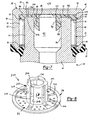
- FIGS. 8-11 depict an alternate embodiment thrust washer identified at reference numeral 200.
- Thrust washer 200 is substantially similar to thrust washer 54 previously described.
- thrust washer 200 includes a generally cup-shaped prong 202 extending from disk segment 82 in lieu of finger portions 84.
- Prong 202 is generally cylindrically shaped having a side wall 204 and an end wall 206.
- Side wall 204 is interrupted by a plurality of slots 208 extending from end wall 206 to disk segment 82.
- An aperture 210 extends through end wall 206 to allow lubricant to pass therethrough.
- Each remaining portion of side wall 204 includes a protrusion 212 extending radially outwardly from an outer surface 214 of side wall 204.
- Protrusions 212 assure that at least a portion of prong 202 of thrust washer 54 biasedly engages inner surface 90 of lubricant passage 92. Accordingly, first bearing cup assembly 48 is axially retained on trunnion 44.
- FIGS 12 and 13 depict another alternate embodiment thrust washer 300.
- Thrust washer 300 is substantially similar to thrust washers 200 and 54. Accordingly, only the substantial differences will be described hereinafter.
- Thrust washer 300 includes a plurality of fingers 302 extending from disk segment 82. Collectively, circumferentially spaced fingers 302 define the shape of a cone. Each of fingers 302 includes a plurality of radially outwardly extending barbs 304. Barbs 304 are angularly positioned such that a relatively small force is required to insert fingers 302 within lubricant passage 92 but a relatively large force is required to remove fingers 302 from lubricant passage 92.
- Barbs 304 function to provide the increased resistance to removal of fingers 302 from lubricant passage 92 when a removing force is applied. Furthermore, the conical shape of fingers 302 provides an alignment feature assuring ease of assembly of the bearing cup assembly. The smallest portion of the cone is sized to clear inner surface 90. The largest portion of the cone is sized to interfere with inner surface 90 thereby retaining the bearing cup assembly on the trunnion.
- Thrust washer 300 also includes a radially extending flange 308 positioned within a recess 310 formed at the bottom of cup 52.
- Flange 308 is installed within cup 52 as a snap-fit connection where thrust washer 300 is deformed during initial insertion within cup 52 and springs back to an undeformed condition once flange 308 enters recess 310.
- FIGS 14 and 15 show another alternate embodiment thrust washer depicted at reference numeral 400.
- Thrust washer 400 includes a prong 402 extending from disk segment 82.
- Prong 402 includes a bifurcated end 404 defining a pair of fingers 406.
- Each finger 406 includes a radially outwardly extending barb 408.
- Each barb 408 includes a conical lead surface 410, a cylindrical outer surface 412 and a back surface 414.
- Back surface 414 engages a portion of a groove 416 formed within lubricant passage 92.
- thrust washer 400 During the installation of thrust washer 400 into lubricant passage 92, fingers 406 are compressed towards one another as conical lead surfaces 410 engage inner surface 90 of lubricant passage 92. Because thrust washer 400 is constructed from a resilient material such as injection molded plastic, fingers 406 resiliently expand toward their undeformed position as barbs 408 enter groove 416. A snap-fit connection is formed once back surface 414 enters groove 416.
- bearing cup assemblies 48 and 50 are installed on trunnions 44 and 46, the bearing cup assemblies are inserted into leg apertures 28 and 38. Thereafter, cruciform 20 is centered, dynamically balanced and coupled to legs 22 and 32.
- a variety of methods for securing yokes 16 and 18 to cruciform 20 are available.
- One method includes mounting a snap ring 122 within a circumferential groove 124 formed on outer wall surface 70 of bearing cup 52. Snap ring 122 engages inboard surface 24 to retain the bearing assembly.
- portions of outboard surface 26 surrounding apertures 28 may be deformed using processes such as staking or peening to create local areas which engage outer end surface 70 of bearing cup 52.
- Another method involves injecting molten resin within a passageway extending between the leg and the bearing cup.
- the molten resin solidifies to retain the bearing cup within the aperture of the leg.
- Yet another retention method incorporates the use of projections (not shown) extending from legs 22 which may be deformed to engage snap ring 122 against outer end surface 70 of bearing cup 52.
Landscapes
- Engineering & Computer Science (AREA)
- General Engineering & Computer Science (AREA)
- Mechanical Engineering (AREA)
- Chemical & Material Sciences (AREA)
- Oil, Petroleum & Natural Gas (AREA)
- Chemical Kinetics & Catalysis (AREA)
- General Chemical & Material Sciences (AREA)
- Organic Chemistry (AREA)
- Sliding-Contact Bearings (AREA)
Abstract
Description
Claims (25)
- A universal joint comprising:a yoke including a leg having an aperture extending therethrough;a cruciform having a trunnion, said trunnion including a substantially cylindrical portion having an end face and a lubricant passage extending at least partially through said trunnion in communication with said end face;a bearing rotatably positioned on said substantially cylindrical portion; anda thrust washer having a substantially planar disk segment and a prong protruding from said disk segment, said disk segment engaging said end face of said trunnion, said prong engaging an inner surface of said lubricant passage to retain said bearing on said trunnion.
- The universal joint of claim 1 wherein said prong biasedly engages said inner surface.
- The universal joint of claim 1 wherein said prong is at least partially deformed during positioning of said bearing on said substantially cylindrical portion of said trunnion.
- The universal joint of claim 1 wherein said prong includes a plurality of spaced apart finger portions, each finger portion being individually deformable.
- The universal joint of claim 4 wherein at least one of said finger portions includes a radially extending barb engaging said inner surface of said lubricant passage.
- The universal joint of claim 5 wherein said lubricant passage includes a detent positioned on said inner surface and offset from said end face of said trunnion, said barb being positioned within said detent to resist removal of said bearing from said trunnion.
- The universal joint of claim 4 wherein said plurality of spaced apart fingers are circumferentially positioned about an aperture extending through said disk segment.
- The universal joint of claim 7 wherein said circumferentially positioned fingers define said prong to be substantially conically shaped.
- The universal joint of claim 7 wherein at least one of said spaced apart fingers includes a plurality of radially extending and spaced apart barbs, said barbs being arranged at an angle such that a force to insert said fingers into said lubricant passage is substantially less than a force to remove said fingers from said lubricant passage.
- The universal joint of claim 1 wherein said prong is a substantially hollow cylinder having a sidewall and an end wall.
- The universal joint of claim 10 wherein said substantially hollow cylinder includes a plurality of slots extending through said sidewall.
- The universal joint of claim 11 wherein said sidewall includes an outer surface, at least a portion of said sidewall including a projection extending radially outwardly from said outer surface, said projection engaging said inner surface of said lubricant passage.
- A method of assembling a universal joint comprising the steps of:positioning a bearing on a trunnion of a cruciform, said trunnion including a substantially cylindrical portion having an end face and a lubricant passage extending through said end face;coupling a thrust washer to said trunnion, said thrust washer including a substantially planar disk segment and a prong extending therefrom;inserting said prong within said lubricant passage;biasedly engaging said prong with an internal surface of said lubricant passage; andpositioning a bearing cup over said thrust washer and said bearing.
- The method of claim 13 further including coupling a seal to said bearing cup and positioning at least a portion of said seal proximate to said bearing.
- The method of claim 13 wherein the step of positioning said bearing cup over said thrust washer and said bearing occurs before said inserting said prong step.
- The method of claim 13 further including engaging said end face of said trunnion with a surface of said disk segment.
- The method of claim 16 further including engaging an inner surface of a circumferential flange of said thrust washer with an outer surface of said substantially cylindrical portion of said trunnion.
- The method of claim 13 wherein said prong includes a plurality of spaced apart finger portions being cantilevered from said disk segment, at least one said finger portion being deflected during insertion within said lubricant passage.
- The method of claim 18 wherein at least one of said finger portions includes a radially extending barb engaging said inner surface of said lubricant passage.
- The method of claim 19 wherein said lubricant passage includes a detent positioned on said inner surface and offset from said end face of said trunnion, said barb being positioned within said detent to resist removal of said bearing from said trunnion.
- The method of claim 18 wherein said plurality of spaced apart fingers are circumferentially positioned about an aperture extending through said disk segment.
- The method of claim 21 wherein said circumferentially positioned fingers define said prong to be substantially conically shaped.
- The method of claim 13 wherein said prong includes an outer surface with a plurality of barbs radially extending therefrom, said barbs being angularly positioned to provide resistance to removing barbs from said lubricant passage.
- The method of claim 13 wherein said prong is a substantially hollow cylinder having a sidewall and an end wall.
- The method of claim 24 wherein said substantially hollow cylinder includes a plurality of slots extending through said sidewall.
Applications Claiming Priority (2)
| Application Number | Priority Date | Filing Date | Title |
|---|---|---|---|
| US387103 | 1995-02-10 | ||
| US10/387,103 US6827649B2 (en) | 2003-03-12 | 2003-03-12 | Universal joint with friction fit and bearing cup retainer |
Publications (2)
| Publication Number | Publication Date |
|---|---|
| EP1457696A1 true EP1457696A1 (en) | 2004-09-15 |
| EP1457696B1 EP1457696B1 (en) | 2006-08-30 |
Family
ID=32771605
Family Applications (1)
| Application Number | Title | Priority Date | Filing Date |
|---|---|---|---|
| EP04001517A Expired - Lifetime EP1457696B1 (en) | 2003-03-12 | 2004-01-24 | Universal joint with friction and bearing cup retainer |
Country Status (7)
| Country | Link |
|---|---|
| US (3) | US6827649B2 (en) |
| EP (1) | EP1457696B1 (en) |
| JP (1) | JP4117564B2 (en) |
| KR (1) | KR101035088B1 (en) |
| BR (1) | BRPI0400203A (en) |
| DE (1) | DE602004002128T2 (en) |
| ES (1) | ES2271708T3 (en) |
Cited By (5)
| Publication number | Priority date | Publication date | Assignee | Title |
|---|---|---|---|---|
| WO2006089533A3 (en) * | 2005-02-22 | 2006-11-16 | Dieter Faude | Universal joint |
| EP1865216A1 (en) * | 2006-06-05 | 2007-12-12 | JTEKT Corporation | Manufacture method for cross joint |
| EP2105622A3 (en) * | 2008-03-27 | 2010-09-22 | JTEKT Corporation | Cross shaft joint |
| CN103591131A (en) * | 2013-11-07 | 2014-02-19 | 河南三维重工有限公司 | Improved thrust bearing for cross axle type universal coupling cross package |
| CN104822957B (en) * | 2013-08-30 | 2018-01-02 | 日本精工株式会社 | The manufacture method of universal-joint-pin type universal joint |
Families Citing this family (20)
| Publication number | Priority date | Publication date | Assignee | Title |
|---|---|---|---|---|
| US7037199B2 (en) * | 2004-01-16 | 2006-05-02 | Federal-Mogul World Wide, Inc. | Universal joint washer baffle |
| US7338378B1 (en) * | 2004-08-03 | 2008-03-04 | Torque-Traction Technologies Llc | Retainer for universal joint bearing cups |
| JP2007064309A (en) * | 2005-08-30 | 2007-03-15 | Ntn Corp | Shell type roller bearing |
| US20070087846A1 (en) * | 2005-10-07 | 2007-04-19 | Timken Us Corporation | Universal joint with vibration isolation |
| US7736238B2 (en) * | 2007-02-23 | 2010-06-15 | Arvinmeritor Technology, Llc | Retained needle thrust washer |
| US20090011841A1 (en) * | 2007-07-03 | 2009-01-08 | Torque-Traction Technologies Llc | Thrust washer for universal joint cross |
| US7887422B2 (en) * | 2007-08-02 | 2011-02-15 | American Axle & Manufacturing, Inc. | Universal joint with bearing cup retention mechanism |
| DE102008028115A1 (en) * | 2008-06-13 | 2009-12-24 | Carl Freudenberg Kg | camp |
| US8316731B2 (en) | 2008-10-10 | 2012-11-27 | American Axle & Manufacturing, Inc. | Power transmission device with torque-resistant seal |
| US20100113166A1 (en) * | 2008-11-04 | 2010-05-06 | Overholt John D | Propshaft assembly with universal joint having non-conductive sleeve between yoke and bearing cup |
| US8092310B2 (en) * | 2008-11-04 | 2012-01-10 | American Axle & Manufacturing, Inc. | Propshaft assembly with universal joint having non-conductive sleeve between yoke and bearing cup |
| US8142292B2 (en) | 2008-11-26 | 2012-03-27 | American Axle & Manufacturing, Inc. | Universal joint with trunnion shaft seal assembly |
| US8256328B2 (en) * | 2009-06-10 | 2012-09-04 | Magna Powertrain Of America, Inc. | Power transfer unit with output shaft having integrated joint assembly |
| US20110011200A1 (en) * | 2009-07-16 | 2011-01-20 | Koyo Bearings Usa Llc | Bearing for a Connecting Rod |
| US10080552B2 (en) * | 2014-04-21 | 2018-09-25 | Covidien Lp | Adapter assembly with gimbal for interconnecting electromechanical surgical devices and surgical loading units, and surgical systems thereof |
| DE102014224751A1 (en) * | 2014-12-03 | 2016-05-25 | Schaeffler Technologies AG & Co. KG | Journal bearing for universal joints and method for producing a journal bearing |
| US10226239B2 (en) * | 2015-04-10 | 2019-03-12 | Covidien Lp | Adapter assembly with gimbal for interconnecting electromechanical surgical devices and surgical loading units, and surgical systems thereof |
| DE112018000482T5 (en) | 2017-01-23 | 2019-10-31 | Dana Automotive Systems Group, Llc | LOCKING BAG |
| CN116871883B (en) * | 2023-09-04 | 2023-12-15 | 万向钱潮股份公司 | Universal joint installation method |
| US12497995B2 (en) | 2024-01-17 | 2025-12-16 | Hamilton Sundstrand Corporation | Microscopic surface texturing for shouldered shaft and bearing pads |
Citations (5)
| Publication number | Priority date | Publication date | Assignee | Title |
|---|---|---|---|---|
| FR1278541A (en) * | 1961-01-31 | 1961-12-08 | Gelenkwellenbau Gmbh | Needle bearing for articulated shaft cross members |
| US4650440A (en) * | 1984-03-24 | 1987-03-17 | Brd Company Limited | Lubrication of hookes universal joints |
| US4710150A (en) * | 1984-06-15 | 1987-12-01 | Glaenzer Spicer | Sealing device for a universal joint |
| JPH11125263A (en) * | 1997-10-22 | 1999-05-11 | Hino Motors Ltd | Grease valve of universal joint |
| US6129634A (en) * | 1998-11-13 | 2000-10-10 | Dana Corporation | Thrust washer for universal joint |
Family Cites Families (57)
| Publication number | Priority date | Publication date | Assignee | Title |
|---|---|---|---|---|
| US2037947A (en) * | 1934-01-22 | 1936-04-21 | Borg Warner | Universal joint |
| US3200615A (en) | 1963-08-14 | 1965-08-17 | Borg Warner | Sealing element |
| US3377820A (en) | 1966-09-07 | 1968-04-16 | Cleveland Steel Products Corp | Universal joint seal |
| US3479840A (en) | 1968-04-16 | 1969-11-25 | Dana Corp | Trunnion seal for cardan-type universal joint |
| SE333279B (en) | 1969-06-30 | 1971-03-08 | Skf Svenska Kullagerfab Ab | SUPPORT AND SEALING FOR ROLLING STOCK |
| US3595586A (en) | 1969-09-10 | 1971-07-27 | Anderson Associates Inc | Lubricant seal for making cylindrical objects |
| FR2123796A5 (en) | 1971-02-01 | 1972-09-15 | Pitner Alfred | |
| BE791371A (en) * | 1971-11-17 | 1973-03-01 | Western Electric Co | DIGITAL DEMODULATOR FOR PHASE MODULATION DATA TRANSMISSION SYSTEM |
| FR2183397A5 (en) | 1972-05-05 | 1973-12-14 | Glaenzer Spicer Sa | |
| US3858413A (en) | 1973-05-02 | 1975-01-07 | Jury Mitrofanovich Nemtsov | Universal joint |
| FR2231261A5 (en) | 1973-05-25 | 1974-12-20 | Pitner Alfred | |
| GB1480650A (en) | 1973-08-23 | 1977-07-20 | Nadella & Pitner | Universal joints |
| US3906746A (en) | 1974-06-20 | 1975-09-23 | Dana Corp | Universal joint sealing |
| US4021085A (en) | 1975-11-06 | 1977-05-03 | Ford Motor Company | Universal joint seal |
| US4138863A (en) | 1977-08-25 | 1979-02-13 | Rockford Acromatic Products Co. | Universal joint cross with adjustable bearing cups |
| DE2908713C2 (en) | 1979-03-06 | 1985-04-18 | Skf Kugellagerfabriken Gmbh, 8720 Schweinfurt | Seal for bearing bushes |
| HU179667B (en) | 1979-12-28 | 1982-11-29 | Autoipari Kutato Intezet | Turn angle limiting device for jointed vehicle |
| US4445875A (en) * | 1980-12-03 | 1984-05-01 | Matsui Universal Joint Manufacturing Company | Universal joint |
| FR2519407B1 (en) * | 1982-01-07 | 1986-03-21 | Glaenzer Spicer Sa | LUBRICATION DEVICE, PARTICULARLY FOR CARDAN JOINT CROSSOVER |
| FR2526896B1 (en) | 1982-05-15 | 1986-10-10 | Skf Kugellagerfabriken Gmbh | SEALING DEVICE FOR BEARINGS |
| US4515574A (en) | 1983-02-16 | 1985-05-07 | The Zeller Corporation | Universal joint seal with multiple lips |
| US4530675A (en) | 1983-02-16 | 1985-07-23 | The Zeller Corporation | Internal universal joint seal with multiple lips |
| JPS6030829A (en) * | 1983-07-26 | 1985-02-16 | Matsui Seisakusho:Kk | Universal joint |
| US4810233A (en) | 1984-03-27 | 1989-03-07 | Borg-Warner Corporation | Interlocking universal joint seal assembly |
| DE3428389A1 (en) | 1984-08-01 | 1986-02-13 | FAG Kugelfischer Georg Schäfer KGaA, 8720 Schweinfurt | PROTECTIVE CAP FOR THE SEAL OF A UNIVERSAL JOINT |
| DE8437288U1 (en) | 1984-12-20 | 1985-03-21 | Skf Kugellagerfabriken Gmbh, 8720 Schweinfurt | Sealing arrangement for bearing bushes, in particular for universal joints |
| JPH0648012B2 (en) * | 1985-02-07 | 1994-06-22 | 株式会社松井製作所 | Universal Sardin |
| JPH0686887B2 (en) * | 1985-02-12 | 1994-11-02 | 株式会社松井製作所 | Universal Sardin |
| DE3615929C1 (en) * | 1986-05-12 | 1987-09-24 | Gelenkwellenbau Gmbh | Cone cross |
| DE3639315C1 (en) | 1986-11-17 | 1988-04-14 | Gelenkwellenbau Gmbh | Device for sealing a roller bearing, in particular bearing bushes of a universal joint |
| US4861315A (en) | 1987-04-10 | 1989-08-29 | The Zeller Corporation | Flexible internal universal joint seal |
| DE3806397A1 (en) | 1988-02-29 | 1989-09-28 | Gkn Cardantec | BEARING ARRANGEMENT FOR A PIN CROSS OF A CROSS JOINT |
| FR2628998B1 (en) | 1988-03-23 | 1990-12-28 | Glaenzer Spicer Sa | METHOD FOR MANUFACTURING A GROOVED TRUCK MEMBER, AND FORMING METHOD AND TOOL FOR GROOVING SAME |
| DE8805833U1 (en) | 1988-05-03 | 1988-07-21 | SKF GmbH, 8720 Schweinfurt | Sealing ring for bearings, especially for bearing bushes of universal joints |
| US5342240A (en) | 1989-07-12 | 1994-08-30 | The Zeller Corporation | High capacity universal joint |
| US5256107A (en) | 1990-02-08 | 1993-10-26 | Toyota Jidosha Kabushiki Kaisha | Sliding type constant velocity universal joint having regulating device for maintaining position of roller constant |
| JP3035116B2 (en) * | 1993-05-14 | 2000-04-17 | 株式会社松井製作所 | Manufacturing method of thrust washer for universal joint |
| JP3106805B2 (en) * | 1993-10-14 | 2000-11-06 | 富士電機株式会社 | Pressure difference measuring method and displacement converter |
| JPH07217668A (en) | 1994-02-04 | 1995-08-15 | Unisia Jecs Corp | Universal joint sealing device |
| DE4412132C5 (en) | 1994-04-08 | 2005-07-28 | Ina-Schaeffler Kg | Sealing for a universal joint box |
| US5813916A (en) | 1995-05-03 | 1998-09-29 | Meritor Heavy Vehicle Systems, Llc | Retained needle thrust washer |
| US5626520A (en) | 1995-06-14 | 1997-05-06 | The Zeller Corporation | Reversible universal joint seal |
| DE19622444C1 (en) | 1996-06-05 | 1998-02-12 | Gkn Automotive Ag | Cross pin set for universal joints |
| DE19622446C1 (en) | 1996-06-05 | 1997-10-16 | Gkn Automotive Ag | Journal cross fitting for universal joint of motor vehicle |
| US5716277A (en) | 1996-06-10 | 1998-02-10 | Dana Corporation | Seal for a universal joint trunnion |
| US5725431A (en) | 1996-09-26 | 1998-03-10 | Dana Corporation | Thrust washer for universal joint having preloading thrust surfaces |
| US5865678A (en) | 1996-12-16 | 1999-02-02 | Dana Corporation | Two-piece thrust washer for universal joint |
| US6162126A (en) | 1998-01-12 | 2000-12-19 | American Axle & Manufacturing, Inc. | Universal joint |
| US6050899A (en) | 1998-05-15 | 2000-04-18 | Neapco, Inc. | Sealing system for a universal joint assembly |
| US6077166A (en) | 1998-06-08 | 2000-06-20 | Dana Corporation | Dust guard and cross assembly for a universal joint |
| US6059663A (en) | 1998-07-13 | 2000-05-09 | Neapco Inc. | One-piece sealing system for a universal joint assembly |
| US6264566B1 (en) | 1998-12-31 | 2001-07-24 | Dana Corporation | Thrust washer for universal joint |
| US6336868B1 (en) | 1999-04-06 | 2002-01-08 | American Axle & Manufacturing, Inc. | Universal joint with thrust washer |
| US6280335B1 (en) | 2000-02-01 | 2001-08-28 | American Axle & Manufacturing, Inc. | Universal joint |
| US6357757B1 (en) | 2000-03-07 | 2002-03-19 | American Axle & Manufacturing, Inc. | Integral seal protector/labyrinth |
| US6406373B1 (en) | 2000-12-21 | 2002-06-18 | Spicer Driveshaft, Inc. | Dust guard and cross assembly for a universal joint |
| DE10145536A1 (en) * | 2001-09-14 | 2003-07-31 | Ina Schaeffler Kg | Storage for universal joint pin |
-
2003
- 2003-03-12 US US10/387,103 patent/US6827649B2/en not_active Expired - Lifetime
-
2004
- 2004-01-24 ES ES04001517T patent/ES2271708T3/en not_active Expired - Lifetime
- 2004-01-24 EP EP04001517A patent/EP1457696B1/en not_active Expired - Lifetime
- 2004-01-24 DE DE602004002128T patent/DE602004002128T2/en not_active Expired - Lifetime
- 2004-03-08 JP JP2004064508A patent/JP4117564B2/en not_active Expired - Lifetime
- 2004-03-09 BR BR0400203-2A patent/BRPI0400203A/en active Search and Examination
- 2004-03-10 KR KR1020040016105A patent/KR101035088B1/en not_active Expired - Lifetime
- 2004-12-01 US US11/001,499 patent/US7044859B2/en not_active Expired - Lifetime
-
2006
- 2006-05-11 US US11/432,691 patent/US7189162B2/en not_active Expired - Lifetime
Patent Citations (5)
| Publication number | Priority date | Publication date | Assignee | Title |
|---|---|---|---|---|
| FR1278541A (en) * | 1961-01-31 | 1961-12-08 | Gelenkwellenbau Gmbh | Needle bearing for articulated shaft cross members |
| US4650440A (en) * | 1984-03-24 | 1987-03-17 | Brd Company Limited | Lubrication of hookes universal joints |
| US4710150A (en) * | 1984-06-15 | 1987-12-01 | Glaenzer Spicer | Sealing device for a universal joint |
| JPH11125263A (en) * | 1997-10-22 | 1999-05-11 | Hino Motors Ltd | Grease valve of universal joint |
| US6129634A (en) * | 1998-11-13 | 2000-10-10 | Dana Corporation | Thrust washer for universal joint |
Non-Patent Citations (1)
| Title |
|---|
| PATENT ABSTRACTS OF JAPAN vol. 1999, no. 10 31 August 1999 (1999-08-31) * |
Cited By (5)
| Publication number | Priority date | Publication date | Assignee | Title |
|---|---|---|---|---|
| WO2006089533A3 (en) * | 2005-02-22 | 2006-11-16 | Dieter Faude | Universal joint |
| EP1865216A1 (en) * | 2006-06-05 | 2007-12-12 | JTEKT Corporation | Manufacture method for cross joint |
| EP2105622A3 (en) * | 2008-03-27 | 2010-09-22 | JTEKT Corporation | Cross shaft joint |
| CN104822957B (en) * | 2013-08-30 | 2018-01-02 | 日本精工株式会社 | The manufacture method of universal-joint-pin type universal joint |
| CN103591131A (en) * | 2013-11-07 | 2014-02-19 | 河南三维重工有限公司 | Improved thrust bearing for cross axle type universal coupling cross package |
Also Published As
| Publication number | Publication date |
|---|---|
| US7044859B2 (en) | 2006-05-16 |
| BRPI0400203A (en) | 2004-12-28 |
| US20060205520A1 (en) | 2006-09-14 |
| KR20040080352A (en) | 2004-09-18 |
| ES2271708T3 (en) | 2007-04-16 |
| KR101035088B1 (en) | 2011-05-19 |
| DE602004002128T2 (en) | 2006-12-21 |
| US6827649B2 (en) | 2004-12-07 |
| US20050079917A1 (en) | 2005-04-14 |
| US20040180723A1 (en) | 2004-09-16 |
| US7189162B2 (en) | 2007-03-13 |
| JP2004278790A (en) | 2004-10-07 |
| JP4117564B2 (en) | 2008-07-16 |
| DE602004002128D1 (en) | 2006-10-12 |
| EP1457696B1 (en) | 2006-08-30 |
Similar Documents
| Publication | Publication Date | Title |
|---|---|---|
| EP1457696B1 (en) | Universal joint with friction and bearing cup retainer | |
| EP1469215B1 (en) | Universal joint with bearing cup retention thrust washer | |
| EP1122452B1 (en) | Universal joint | |
| EP1045159B1 (en) | Universal joint | |
| EP1471276B1 (en) | Universal joint with venting seal assembly | |
| EP1620656B1 (en) | Universal joint with integral seal deflector and retainer assembly | |
| US6994627B2 (en) | Universal joint | |
| US6837795B2 (en) | Universal joint with bearing cup retention seal assembly | |
| US7004841B2 (en) | Driveshaft assembly with retention mechanism | |
| BRPI0401115B1 (en) | UNIVERSAL GASKET WASHER FOR RETAINING MANCAL CUP AND MOUNTING METHOD FOR A UNIVERSAL JOINT |
Legal Events
| Date | Code | Title | Description |
|---|---|---|---|
| PUAI | Public reference made under article 153(3) epc to a published international application that has entered the european phase |
Free format text: ORIGINAL CODE: 0009012 |
|
| AK | Designated contracting states |
Kind code of ref document: A1 Designated state(s): AT BE BG CH CY CZ DE DK EE ES FI FR GB GR HU IE IT LI LU MC NL PT RO SE SI SK TR |
|
| AX | Request for extension of the european patent |
Extension state: AL LT LV MK |
|
| 17P | Request for examination filed |
Effective date: 20041022 |
|
| 17Q | First examination report despatched |
Effective date: 20041124 |
|
| AKX | Designation fees paid |
Designated state(s): DE ES FR GB IT |
|
| RAP1 | Party data changed (applicant data changed or rights of an application transferred) |
Owner name: AMERICAN AXLE & MANUFACTURING, INC. |
|
| GRAP | Despatch of communication of intention to grant a patent |
Free format text: ORIGINAL CODE: EPIDOSNIGR1 |
|
| GRAS | Grant fee paid |
Free format text: ORIGINAL CODE: EPIDOSNIGR3 |
|
| GRAA | (expected) grant |
Free format text: ORIGINAL CODE: 0009210 |
|
| AK | Designated contracting states |
Kind code of ref document: B1 Designated state(s): DE ES FR GB IT |
|
| PG25 | Lapsed in a contracting state [announced via postgrant information from national office to epo] |
Ref country code: IT Free format text: LAPSE BECAUSE OF FAILURE TO SUBMIT A TRANSLATION OF THE DESCRIPTION OR TO PAY THE FEE WITHIN THE PRESCRIBED TIME-LIMIT;WARNING: LAPSES OF ITALIAN PATENTS WITH EFFECTIVE DATE BEFORE 2007 MAY HAVE OCCURRED AT ANY TIME BEFORE 2007. THE CORRECT EFFECTIVE DATE MAY BE DIFFERENT FROM THE ONE RECORDED. Effective date: 20060830 |
|
| REG | Reference to a national code |
Ref country code: GB Ref legal event code: FG4D |
|
| REF | Corresponds to: |
Ref document number: 602004002128 Country of ref document: DE Date of ref document: 20061012 Kind code of ref document: P |
|
| ET | Fr: translation filed | ||
| REG | Reference to a national code |
Ref country code: ES Ref legal event code: FG2A Ref document number: 2271708 Country of ref document: ES Kind code of ref document: T3 |
|
| PLBE | No opposition filed within time limit |
Free format text: ORIGINAL CODE: 0009261 |
|
| STAA | Information on the status of an ep patent application or granted ep patent |
Free format text: STATUS: NO OPPOSITION FILED WITHIN TIME LIMIT |
|
| 26N | No opposition filed |
Effective date: 20070531 |
|
| REG | Reference to a national code |
Ref country code: FR Ref legal event code: PLFP Year of fee payment: 13 |
|
| PGFP | Annual fee paid to national office [announced via postgrant information from national office to epo] |
Ref country code: ES Payment date: 20151214 Year of fee payment: 13 Ref country code: FR Payment date: 20151208 Year of fee payment: 13 |
|
| PGFP | Annual fee paid to national office [announced via postgrant information from national office to epo] |
Ref country code: IT Payment date: 20160127 Year of fee payment: 13 |
|
| PGFP | Annual fee paid to national office [announced via postgrant information from national office to epo] |
Ref country code: GB Payment date: 20160120 Year of fee payment: 13 |
|
| GBPC | Gb: european patent ceased through non-payment of renewal fee |
Effective date: 20170124 |
|
| REG | Reference to a national code |
Ref country code: FR Ref legal event code: ST Effective date: 20170929 |
|
| PG25 | Lapsed in a contracting state [announced via postgrant information from national office to epo] |
Ref country code: FR Free format text: LAPSE BECAUSE OF NON-PAYMENT OF DUE FEES Effective date: 20170131 |
|
| PG25 | Lapsed in a contracting state [announced via postgrant information from national office to epo] |
Ref country code: GB Free format text: LAPSE BECAUSE OF NON-PAYMENT OF DUE FEES Effective date: 20170124 |
|
| PG25 | Lapsed in a contracting state [announced via postgrant information from national office to epo] |
Ref country code: IT Free format text: LAPSE BECAUSE OF NON-PAYMENT OF DUE FEES Effective date: 20170124 |
|
| PG25 | Lapsed in a contracting state [announced via postgrant information from national office to epo] |
Ref country code: ES Free format text: LAPSE BECAUSE OF NON-PAYMENT OF DUE FEES Effective date: 20170125 |
|
| REG | Reference to a national code |
Ref country code: ES Ref legal event code: FD2A Effective date: 20181116 |
|
| PGFP | Annual fee paid to national office [announced via postgrant information from national office to epo] |
Ref country code: DE Payment date: 20200121 Year of fee payment: 17 |
|
| REG | Reference to a national code |
Ref country code: DE Ref legal event code: R119 Ref document number: 602004002128 Country of ref document: DE |
|
| PG25 | Lapsed in a contracting state [announced via postgrant information from national office to epo] |
Ref country code: DE Free format text: LAPSE BECAUSE OF NON-PAYMENT OF DUE FEES Effective date: 20210803 |