EP1457440A1 - Method and machine for transferring packets - Google Patents
Method and machine for transferring packets Download PDFInfo
- Publication number
- EP1457440A1 EP1457440A1 EP04100945A EP04100945A EP1457440A1 EP 1457440 A1 EP1457440 A1 EP 1457440A1 EP 04100945 A EP04100945 A EP 04100945A EP 04100945 A EP04100945 A EP 04100945A EP 1457440 A1 EP1457440 A1 EP 1457440A1
- Authority
- EP
- European Patent Office
- Prior art keywords
- transfer
- feed
- packet
- lead packet
- machine
- Prior art date
- Legal status (The legal status is an assumption and is not a legal conclusion. Google has not performed a legal analysis and makes no representation as to the accuracy of the status listed.)
- Withdrawn
Links
- 238000000034 method Methods 0.000 title claims abstract description 22
- 230000001105 regulatory effect Effects 0.000 claims description 4
- 230000001276 controlling effect Effects 0.000 claims 1
- 230000007423 decrease Effects 0.000 claims 1
- 235000019504 cigarettes Nutrition 0.000 description 5
- 238000012856 packing Methods 0.000 description 3
- 230000000712 assembly Effects 0.000 description 1
- 238000000429 assembly Methods 0.000 description 1
- 230000002452 interceptive effect Effects 0.000 description 1
- 238000011144 upstream manufacturing Methods 0.000 description 1
Images


Classifications
-
- B—PERFORMING OPERATIONS; TRANSPORTING
- B65—CONVEYING; PACKING; STORING; HANDLING THIN OR FILAMENTARY MATERIAL
- B65G—TRANSPORT OR STORAGE DEVICES, e.g. CONVEYORS FOR LOADING OR TIPPING, SHOP CONVEYOR SYSTEMS OR PNEUMATIC TUBE CONVEYORS
- B65G47/00—Article or material-handling devices associated with conveyors; Methods employing such devices
- B65G47/22—Devices influencing the relative position or the attitude of articles during transit by conveyors
- B65G47/26—Devices influencing the relative position or the attitude of articles during transit by conveyors arranging the articles, e.g. varying spacing between individual articles
- B65G47/30—Devices influencing the relative position or the attitude of articles during transit by conveyors arranging the articles, e.g. varying spacing between individual articles during transit by a series of conveyors
- B65G47/32—Applications of transfer devices
-
- B—PERFORMING OPERATIONS; TRANSPORTING
- B65—CONVEYING; PACKING; STORING; HANDLING THIN OR FILAMENTARY MATERIAL
- B65G—TRANSPORT OR STORAGE DEVICES, e.g. CONVEYORS FOR LOADING OR TIPPING, SHOP CONVEYOR SYSTEMS OR PNEUMATIC TUBE CONVEYORS
- B65G47/00—Article or material-handling devices associated with conveyors; Methods employing such devices
- B65G47/74—Feeding, transfer, or discharging devices of particular kinds or types
- B65G47/82—Rotary or reciprocating members for direct action on articles or materials, e.g. pushers, rakes, shovels
-
- B—PERFORMING OPERATIONS; TRANSPORTING
- B65—CONVEYING; PACKING; STORING; HANDLING THIN OR FILAMENTARY MATERIAL
- B65G—TRANSPORT OR STORAGE DEVICES, e.g. CONVEYORS FOR LOADING OR TIPPING, SHOP CONVEYOR SYSTEMS OR PNEUMATIC TUBE CONVEYORS
- B65G2201/00—Indexing codes relating to handling devices, e.g. conveyors, characterised by the type of product or load being conveyed or handled
- B65G2201/02—Articles
- B65G2201/0235—Containers
- B65G2201/025—Boxes
Definitions
- the present invention relates to a method and machine for transferring packets.
- the present invention may be used to advantage in the packing of cigarettes, to which the following description refers purely by way of example.
- a continuous line of packets of cigarettes is fed in a feed direction to a transfer station.
- the line of packets travelling in the feed direction is arrested when the lead packet, i.e. the first packet in the line, intercepts an end wall at the transfer station; at which point, the lead packet is transferred in a transfer direction substantially perpendicular to the feed direction to separate the lead packet from the line; and, once transferred, the lead packet is further conveyed along an output path.
- the above operations are obviously repeated for each packet occupying the lead position in the line.
- the line of packets is fed to the transfer station at relatively high speed to permit high output rates and prevent gaps forming between successive packets in the line.
- the lead packet contacts the end wall with fairly considerable force capable of damaging the lead packet.
- the lead packet slides against the end wall, thus possibly undergoing further damage.
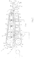
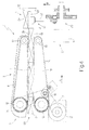
- Number 1 in Figure 1 indicates as a whole a machine for transferring substantially parallelepiped-shaped packets 2, in particular packets of cigarettes, from a known packing machine not shown.
- machine 1 comprises a feed unit 3 for feeding packets 2 horizontally in a feed direction A to a transfer station 4; and a transfer unit 5 for transferring at least one packet 2a, located at transfer station 4, to an output station 6 in a transfer direction B substantially perpendicular to feed direction A.
- Feed unit 3 comprises a conveyor belt 7 which feeds packets 2 to a further two-belt conveyor 8.
- Conveyor 8 feeds the packets to transfer station 4, is located downstream from conveyor belt 7, and comprises a top conveying assembly 9 and a bottom conveying assembly 10 defining, in between, a feed channel 11 for packets 2.
- Each conveying assembly 9, 10 comprises a drive pulley 12, and a number of - in the example shown, five - idle pulleys 13; and the respective pulleys 12 and 13 of the two assemblies are located on opposite sides of channel 11.
- Each conveying assembly 9, 10 comprises a belt 14 looped about relative pulleys 12 and 13 and which engages the walls of packets 2 to feed packets 2 in feed direction A.
- Conveying assembly 9 has a known guide device (not shown) for raising conveying assembly 9 to adjust the distance between it and conveying assembly 10; and a known locking device (not shown) operated by a lever 15 to lock conveying assembly 9 in a given position.
- Conveyor 8 comprises an electric motor 16 for driving pulleys 12 by means of a belt 17 (shown schematically in Figure 4) which is kept taut by a tension pulley 18.
- conveyor 8 comprises a slide plate 19 located immediately downstream from conveying assembly 10 and having a top slide surface substantially coplanar with a bottom surface of channel 11.
- Transfer unit 5 comprises a lifter 20, in turn comprising a lift head 21, and a rod 22, one end of which is integral with lift head 21, and the other end of which is connected by a cam follower to a cam 23 rotated about a respective axis by a motor M ( Figure 4).
- a lifter 20 in turn comprising a lift head 21, and a rod 22, one end of which is integral with lift head 21, and the other end of which is connected by a cam follower to a cam 23 rotated about a respective axis by a motor M ( Figure 4).
- the length, in feed direction A, of lift head 21 is shorter than the length, in feed direction A, of the wall of packet 2a.
- lift head 21 intercepts packet 2a at transfer station 4, and moves upwards in transfer direction B to transfer it to output station 6.
- Machine 1 also comprises a conveying unit 24 located downstream from transfer unit 5 to convey packets 2a along an output path from output station 6.
- Unit 24 comprises a push device 25 for feeding packet 2a at output station 6 onto a belt conveyor 26.
- machine 1 comprises a sensor 27 for detecting any gaps between packets 2 inside channel 11; and a sensor 28 for detecting the position of a second packet 2b behind packet 2a in feed direction A.
- Sensors 27 and 28 are connected to a known control unit (not shown) which controls the speed of motor 16 as a function of the position of lift head 21.
- the speed of motor 16 is also adjusted on the basis of the position of packet 2b determined by sensor 28. More specifically, if packet 2b is ahead with respect to a given predetermined position, motor 16 is slowed down accordingly.
- the known control unit arrests motor 16 and motor M.
- the individual incoming packets from the known packing machine are fed by conveyor belt 7 to conveyor 8 at a constant speed greater than the maximum travelling speed of conveyor 8.
- a continuous line 29 of packets 2 is formed, and of which packet 2a is the lead packet in feed direction A.
- the known control unit adjusts the speed of motor M of transfer unit 5 so that the longer line 29 is, the greater the speed of motor M of transfer unit 5 is.
- the line 29 of packets 2 inside channel 11 is fed by conveyor 8 to transfer station 4 in feed direction A.
- head 21 is moved vertically upwards in transfer direction B.
- line 29 continues moving so that packet 2b pushes packet 2a in feed direction A until packet 2a reaches output station 6 and is separated completely from line 29.
- push device 25 is operated so that packet 2a at the output station is fed along the output path defined at least partly by conveyor 26.
- Lift head 21 moves back and forth in transfer direction B so as to move down after feeding packet 2a to output station 6.
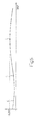
- FIG 5 graph shows, purely by way of example, the travelling speed of line 29 (y axis) as a function of the machine angle of transfer unit 5 (x axis).
- portion C-D represents the downward movement of lift head 21
- point E represents the instant in which head 21 begins moving upwards
- portion E-C represents the upward movement of head 21 (i.e. transfer of packet 2a in transfer direction B).
- the travelling speed of line 29 along portion C-D is relatively low (in particular, less than or equal to the speed along portion D-C) and reaches a maximum when lift head 21 is positioned beneath transfer station 4. Head 21 therefore has enough time to move downwards without coming into contact with line 29, and without interfering with the movement of line 29 in feed direction A.
- the travelling speed of line 29 typically slows down along portion E-C.
- the travelling speed of line 29 in feed direction A is also preferably varied as a function of the position of packet 2b as head 21 begins moving upwards.
- the real position of packet 2b is determined the instant packet 2a begins to be lifted, and is compared with an ideal theoretical position.
- the travelling speed is increased slightly with respect to that shown by way of example in Figure 5; and, conversely, if packet 2b is ahead of the ideal position, the travelling speed is reduced slightly with respect to that shown by way of example in Figure 5.
Landscapes
- Engineering & Computer Science (AREA)
- Mechanical Engineering (AREA)
- Wrapping Of Specific Fragile Articles (AREA)
- Auxiliary Devices For And Details Of Packaging Control (AREA)
- Intermediate Stations On Conveyors (AREA)
- Relays Between Conveyors (AREA)
Abstract
A method and machine (1) for transferring packets (2), whereby, as a continuous line (29) of packets (2) is fed in a first direction (A), the first packet (2a) in the line (29) is transferred in a second direction (B) perpendicular to the first direction (A), while the line (29) and the first packet (2a) continue travelling in the first direction (A); the first packet (2a) is subsequently conveyed in the second direction (B) along an output path. <IMAGE>
Description
The present invention relates to a method and
machine for transferring packets.
The present invention may be used to advantage in
the packing of cigarettes, to which the following
description refers purely by way of example.
In automatic machines for transferring packets of
cigarettes, a continuous line of packets of cigarettes is
fed in a feed direction to a transfer station. The line
of packets travelling in the feed direction is arrested
when the lead packet, i.e. the first packet in the line,
intercepts an end wall at the transfer station; at which
point, the lead packet is transferred in a transfer
direction substantially perpendicular to the feed
direction to separate the lead packet from the line; and,
once transferred, the lead packet is further conveyed
along an output path. The above operations are obviously
repeated for each packet occupying the lead position in
the line.
In modern automatic machines, the line of packets is
fed to the transfer station at relatively high speed to
permit high output rates and prevent gaps forming between
successive packets in the line. As a result, the lead
packet contacts the end wall with fairly considerable
force capable of damaging the lead packet. Moreover, as
it is being fed in the transfer direction, the lead
packet slides against the end wall, thus possibly
undergoing further damage.
It is an object of the present invention to provide
a method of transferring packets, designed to eliminate
the aforementioned drawbacks, and which at the same time
is cheap and easy to implement.
According to the present invention, there is
provided a method of transferring packets, as claimed in
Claim 1 and, preferably, in any one of the following
Claims depending directly or indirectly on Claim 1.
According to the present invention, there is also
provided a machine for transferring packets, as claimed
in Claim 15 and, preferably, in any one of the following
Claims depending directly or indirectly on Claim 15.
A non-limiting embodiment of the present invention
will be described by way of example with reference to the
accompanying drawings, in which:
Number 1 in Figure 1 indicates as a whole a machine
for transferring substantially parallelepiped-shaped
packets 2, in particular packets of cigarettes, from a
known packing machine not shown.
With reference to Figures 1, 2 and 3, machine 1
comprises a feed unit 3 for feeding packets 2
horizontally in a feed direction A to a transfer station
4; and a transfer unit 5 for transferring at least one
packet 2a, located at transfer station 4, to an output
station 6 in a transfer direction B substantially
perpendicular to feed direction A.
Each conveying assembly 9, 10 comprises a drive
pulley 12, and a number of - in the example shown, five -
idle pulleys 13; and the respective pulleys 12 and 13 of
the two assemblies are located on opposite sides of
channel 11.
Each conveying assembly 9, 10 comprises a belt 14
looped about relative pulleys 12 and 13 and which engages
the walls of packets 2 to feed packets 2 in feed
direction A.
Finally, conveyor 8 comprises a slide plate 19
located immediately downstream from conveying assembly 10
and having a top slide surface substantially coplanar
with a bottom surface of channel 11.
In actual use, lift head 21 intercepts packet 2a at
transfer station 4, and moves upwards in transfer
direction B to transfer it to output station 6.
Machine 1 also comprises a conveying unit 24 located
downstream from transfer unit 5 to convey packets 2a
along an output path from output station 6. Unit 24
comprises a push device 25 for feeding packet 2a at
output station 6 onto a belt conveyor 26.
Finally, machine 1 comprises a sensor 27 for
detecting any gaps between packets 2 inside channel 11;
and a sensor 28 for detecting the position of a second
packet 2b behind packet 2a in feed direction A. Sensors
27 and 28 are connected to a known control unit (not
shown) which controls the speed of motor 16 as a function
of the position of lift head 21. The speed of motor 16 is
also adjusted on the basis of the position of packet 2b
determined by sensor 28. More specifically, if packet 2b
is ahead with respect to a given predetermined position,
motor 16 is slowed down accordingly. When sensor 27
detects, in use, a gap between packets 2 in channel 11,
the known control unit (not shown) arrests motor 16 and
motor M.
In use, the individual incoming packets from the
known packing machine (not shown) are fed by conveyor
belt 7 to conveyor 8 at a constant speed greater than the
maximum travelling speed of conveyor 8. Upstream from
conveyor 8 and inside channel 11, a continuous line 29 of
packets 2 is formed, and of which packet 2a is the lead
packet in feed direction A. On the basis of the length of
line 29, which is determined by known sensors (not
shown), the known control unit (not shown) adjusts the
speed of motor M of transfer unit 5 so that the longer
line 29 is, the greater the speed of motor M of transfer
unit 5 is.
The line 29 of packets 2 inside channel 11 is fed by
conveyor 8 to transfer station 4 in feed direction A.
When packet 2a is positioned correctly at transfer
station 4 so as to be partly supported by lift head 21,
head 21 is moved vertically upwards in transfer direction
B. As packet 2a is being raised, line 29 continues moving
so that packet 2b pushes packet 2a in feed direction A
until packet 2a reaches output station 6 and is separated
completely from line 29.
It should be stressed that the movements of lift
head 21 and the speed at which conveyor 8 conveys line 29
are so regulated that packet 2a never comes into contact
with an end wall 30 located at the end of transfer
station 4 in feed direction A.
At this point, push device 25 is operated so that
packet 2a at the output station is fed along the output
path defined at least partly by conveyor 26. Lift head 21
moves back and forth in transfer direction B so as to
move down after feeding packet 2a to output station 6.
In this connection, it should be stressed that the
movements of lift head 21 and the travelling speed of
line 29 are so regulated that head 21 does not interfere
with the travel of line 29 inside transfer station 4.
More specifically, the travelling speed of line 29 in
feed direction A varies as a function of the position of
lift head 21, and therefore in a definite manner with
time.
The Figure 5 graph shows, purely by way of example,
the travelling speed of line 29 (y axis) as a function of
the machine angle of transfer unit 5 (x axis). In Figure
5, portion C-D represents the downward movement of lift
head 21, point E represents the instant in which head 21
begins moving upwards, and portion E-C represents the
upward movement of head 21 (i.e. transfer of packet 2a in
transfer direction B).
The travelling speed of line 29 along portion C-D is
relatively low (in particular, less than or equal to the
speed along portion D-C) and reaches a maximum when lift
head 21 is positioned beneath transfer station 4. Head 21
therefore has enough time to move downwards without
coming into contact with line 29, and without interfering
with the movement of line 29 in feed direction A. The
travelling speed of line 29 typically slows down along
portion E-C.
It should be pointed out that the travelling speed
of line 29 in feed direction A is also preferably varied
as a function of the position of packet 2b as head 21
begins moving upwards. For which purpose, the real
position of packet 2b is determined the instant packet 2a
begins to be lifted, and is compared with an ideal
theoretical position. When packet 2b falls short of the
ideal position, the travelling speed is increased
slightly with respect to that shown by way of example in
Figure 5; and, conversely, if packet 2b is ahead of the
ideal position, the travelling speed is reduced slightly
with respect to that shown by way of example in Figure 5.
Claims (23)
- A method of transferring packets; the method comprising a feed step of feeding a continuous line (29) of packets (2) at a travelling speed of other than zero in a first direction (A); a transfer step of transferring at least one lead packet (2a) in a second direction (B) substantially perpendicular to the first direction (A), so as to separate said lead packet (2a) from the line (29); and a conveying step subsequent to the transfer step, to convey the lead packet (2a) along an output path; said lead packet (2a) being a lead packet of said line (29) in said first direction (A); and the method being characterized in that said transfer step is performed during said feed step.
- A method as claimed in Claim 1, characterized in that said first direction (A) is a substantially horizontal direction.
- A method as claimed in Claim 2, characterized in that said second direction (B) is a substantially vertical upward direction.
- A method as claimed in any one of Claims 1 to 3, characterized in that the travelling speed varies with time.
- A method as claimed in any one of Claims 1 to 4, characterized in that the lead packet (2a) is transferred in said second direction (B) by mechanical transfer means (5) which engage said lead packet (2a) at a transfer station (4); the movements of the mechanical transfer means (5) and the travelling speed being so regulated that the mechanical transfer means (5) do not interfere with travel of the line (29) of packets (2) in said first direction (A).
- A method as claimed in Claim 5, characterized in that said mechanical transfer means (5) comprise a push member (21) movable back and forth in the second direction (B), and which engages a wall of the lead packet (2a) to transfer the lead packet (2a) in the second direction (B).
- A method as claimed in any one of Claims 1 to 6, characterized in that said feed step includes a first and a second feed substep (D-C, C-D) alternating with each other; the travelling speed during the first feed substep (D-C) being at least equal to the travelling speed during the second feed substep (C-D); and the transfer step (E-C) being performed during said first feed substep (D-C).
- A method as claimed in any one of Claims 5 to 7, characterized in that, during said transfer step (E-C) and said second feed substep (C-D), the mechanical transfer means (5) partly occupy the transfer station (4), so that the line (29) of packets (2) can partly engage the transfer station (4).
- A method as claimed in Claim 8, characterized in that, during the second feed substep (C-D), the mechanical transfer means (5) disengage the transfer station (4) so as not to interfere with travel of the line (29) of packets (2), and so that, at the end of the second feed substep (C-D), the mechanical transfer means (5) are located outside the transfer station (4).
- A method as claimed in any one of Claims 7 to 9, characterized in that the travelling speed varies during the first feed substep (D-C), and reaches a minimum value at the end of the transfer step (E-C) and at the start of the second feed substep (C-D); the end of the transfer step (E-C) and the start of the second feed substep (C-D) being simultaneous.
- A method as claimed in any one of Claims 7 to 10, characterized in that the travelling speed varies during the second feed substep, and reaches a maximum value (E) at the end of the first feed substep (D-C) and at the end of the transfer step (E-C); the end of the first feed substep (D-C) and the end of the transfer step (E-C) being simultaneous.
- A method as claimed in any one of Claims 4 to 11, characterized in that the travelling speed varies with time in a substantially sinusoidal pattern.
- A method as claimed in any one of Claims 5 to 12, characterized in that the travelling speed decreases with time during said transfer step (E-C).
- A method as claimed in any one of Claims 1 to 13, characterized in that, during at least part of the transfer step, the packet travels in the first direction (A) .
- A machine for transferring packets; the machine comprising feed means (3) for feeding a continuous line (29) of packets in a first direction (A) at a travelling speed of other than zero; and mechanical transfer means (5) which engage at least one lead packet (2a) in the line (29) at a transfer station (4), and transfer the lead packet (2a) in a second direction (B) substantially perpendicular to the first direction (A), so as to separate the lead packet (2a) from the line (29); said lead packet (2a) being a lead packet of said line (29) in said first direction (A); and the machine (1) being characterized in that the feed means (3) feed the line (29) of packets into the transfer station (4) while, in use, the mechanical transfer means (5) partly occupy the transfer station (4); the movements of the mechanical transfer means (5) and the travelling speed being so regulated, in use, that the mechanical transfer means (5) do not interfere with travel of the line (29) of packets (2) in the first direction (A).
- A machine as claimed in Claim 15, characterized in that the first direction (A) is substantially horizontal.
- A machine as claimed in Claim 16, characterized in that the second direction (B) is substantially vertical.
- A machine as claimed in Claim 16 or 17, characterized in that the mechanical transfer means (5) transfer the lead packet (2a) to an output station (6); the machine comprising an output conveyor (26), and push means (25) for transferring the lead packet (2a) at the output station (6) to the output conveyor (26).
- A machine as claimed in any one of Claims 15 to 18, characterized by comprising a control unit for controlling said feed means (3) so as to vary said travelling speed as a function of the movements of the mechanical transfer means (5).
- A machine as claimed in Claim 19, characterized by comprising detecting means (28) for detecting the position of a second packet (2b) located, in use, directly behind said lead packet (2a) in a travelling direction of the packets (2); the detecting means (28) being connected to the control unit, which varies the travelling speed as a function of the position of the second packet (2b).
- A machine as claimed in any one of Claims 15 to 20, characterized in that said mechanical transfer means comprise a push member (21), which engages a wall of the lead packet (2a) to transfer the lead packet (2a) in the second direction (B); and actuating means (23, M) for moving the push member (21) back and forth through the transfer station in said second direction (B).
- A machine as claimed in Claim 21, characterized in that the push member (21) engages a wall of the lead packet (2a), and is of a length, in the first direction (A), shorter than the length, in the first direction (A), of the wall of the packet (2).
- A machine as claimed in any one of Claims 15 to 22, for implementing a method as claimed in any one of Claims 1 to 14.
Applications Claiming Priority (2)
| Application Number | Priority Date | Filing Date | Title |
|---|---|---|---|
| IT000129A ITBO20030129A1 (en) | 2003-03-10 | 2003-03-10 | METHOD AND MACHINE FOR THE TRANSFER OF PACKAGES |
| ITBO20030129 | 2003-03-10 |
Publications (1)
| Publication Number | Publication Date |
|---|---|
| EP1457440A1 true EP1457440A1 (en) | 2004-09-15 |
Family
ID=32750461
Family Applications (1)
| Application Number | Title | Priority Date | Filing Date |
|---|---|---|---|
| EP04100945A Withdrawn EP1457440A1 (en) | 2003-03-10 | 2004-03-09 | Method and machine for transferring packets |
Country Status (5)
| Country | Link |
|---|---|
| US (1) | US7108122B2 (en) |
| EP (1) | EP1457440A1 (en) |
| JP (1) | JP2004269261A (en) |
| CN (1) | CN100519366C (en) |
| IT (1) | ITBO20030129A1 (en) |
Cited By (2)
| Publication number | Priority date | Publication date | Assignee | Title |
|---|---|---|---|---|
| EP1746055A3 (en) * | 2005-07-19 | 2007-03-07 | G.D. Societa' per Azioni | Device for handling packets |
| EP2740461A3 (en) * | 2012-12-10 | 2015-08-19 | Evondos Oy | Medication dispenser and method for dispensing medications |
Families Citing this family (3)
| Publication number | Priority date | Publication date | Assignee | Title |
|---|---|---|---|---|
| JP4878639B2 (en) * | 2009-10-29 | 2012-02-15 | 日特エンジニアリング株式会社 | Pallet conveying device and pallet conveying method |
| CN105600417A (en) * | 2015-11-02 | 2016-05-25 | 经纬纺织机械股份有限公司 | Pushing blocking rod mechanism |
| CN107878830A (en) * | 2017-10-30 | 2018-04-06 | 薛伟 | Material mounted box conveys flow |
Citations (4)
| Publication number | Priority date | Publication date | Assignee | Title |
|---|---|---|---|---|
| DE3840394A1 (en) * | 1987-12-03 | 1989-06-15 | Gd Spa | DEVICE FOR FEEDING OBJECTS TO A WORKSTATION |
| US4883163A (en) * | 1986-12-17 | 1989-11-28 | G.D. Societa Per Azioni | Apparatus and method for regularly spacing apart randomly spaced objects while conveying them |
| EP0519400A1 (en) * | 1991-06-21 | 1992-12-23 | G.D Societa' Per Azioni | Device for equally-spaced transportation of randomly arranged incoming products |
| EP0987180A1 (en) * | 1998-08-31 | 2000-03-22 | G.D. S.p.A. | A method of controlling the operation of a packaging line automatically |
Family Cites Families (5)
| Publication number | Priority date | Publication date | Assignee | Title |
|---|---|---|---|---|
| DE19528200A1 (en) * | 1995-08-01 | 1997-02-06 | Topack Verpacktech Gmbh | Device for transferring pack blocks from rod-shaped articles of the tobacco processing industry |
| IT1285962B1 (en) * | 1996-06-21 | 1998-06-26 | Gd Spa | METHOD AND DEVICE FOR THE CONVEYANCE, WITH VERTICAL MOVEMENT, OF PACKAGES OF CIGARETTES |
| IT1299982B1 (en) * | 1998-04-22 | 2000-04-04 | Gd Spa | METHOD FOR THE CREATION OF CIGARETTE PACKAGES AND PLANT FOR THE IMPLEMENTATION OF THIS METHOD. |
| JPH11314749A (en) * | 1998-04-30 | 1999-11-16 | O M Ltd | Article lateral takeout method and device |
| DE19853313A1 (en) * | 1998-11-19 | 2000-05-25 | Topack Verpacktech Gmbh | Device for transferring pack blocks from rod-shaped articles |
-
2003
- 2003-03-10 IT IT000129A patent/ITBO20030129A1/en unknown
-
2004
- 2004-03-05 US US10/794,773 patent/US7108122B2/en not_active Expired - Fee Related
- 2004-03-08 CN CNB2004100064635A patent/CN100519366C/en not_active Expired - Fee Related
- 2004-03-09 EP EP04100945A patent/EP1457440A1/en not_active Withdrawn
- 2004-03-10 JP JP2004067748A patent/JP2004269261A/en active Pending
Patent Citations (4)
| Publication number | Priority date | Publication date | Assignee | Title |
|---|---|---|---|---|
| US4883163A (en) * | 1986-12-17 | 1989-11-28 | G.D. Societa Per Azioni | Apparatus and method for regularly spacing apart randomly spaced objects while conveying them |
| DE3840394A1 (en) * | 1987-12-03 | 1989-06-15 | Gd Spa | DEVICE FOR FEEDING OBJECTS TO A WORKSTATION |
| EP0519400A1 (en) * | 1991-06-21 | 1992-12-23 | G.D Societa' Per Azioni | Device for equally-spaced transportation of randomly arranged incoming products |
| EP0987180A1 (en) * | 1998-08-31 | 2000-03-22 | G.D. S.p.A. | A method of controlling the operation of a packaging line automatically |
Cited By (3)
| Publication number | Priority date | Publication date | Assignee | Title |
|---|---|---|---|---|
| EP1746055A3 (en) * | 2005-07-19 | 2007-03-07 | G.D. Societa' per Azioni | Device for handling packets |
| US7475769B2 (en) | 2005-07-19 | 2009-01-13 | G.D. Societa' Per Azioni | Device for handling packets |
| EP2740461A3 (en) * | 2012-12-10 | 2015-08-19 | Evondos Oy | Medication dispenser and method for dispensing medications |
Also Published As
| Publication number | Publication date |
|---|---|
| CN1550415A (en) | 2004-12-01 |
| US7108122B2 (en) | 2006-09-19 |
| US20040238325A1 (en) | 2004-12-02 |
| CN100519366C (en) | 2009-07-29 |
| JP2004269261A (en) | 2004-09-30 |
| ITBO20030129A1 (en) | 2004-09-11 |
Similar Documents
| Publication | Publication Date | Title |
|---|---|---|
| EP1719706B1 (en) | Multipurpose cartoning machine | |
| US7651089B2 (en) | Method and device for forming stacks of flat elements | |
| KR101784660B1 (en) | Transfer apparatus for hub element | |
| US7108122B2 (en) | Method and machine for transferring packets | |
| US5887701A (en) | Method and unit for forming and conveying groups of products | |
| EP0801014B1 (en) | Product conveying method | |
| EP4011808B1 (en) | Apparatus for moving and grouping flat products | |
| EP1300351B1 (en) | Method and device for the orderly supply of randomly received products | |
| US6951272B2 (en) | Signature-stacking apparatus | |
| EP0806380A1 (en) | Method and unit for ordering products | |
| EP1975289A2 (en) | Bobbin transport system | |
| JP4773061B2 (en) | Multi-function paper path gate selector system | |
| US6461102B2 (en) | Charging apparatus | |
| EP1003675B1 (en) | Transfer mechanism | |
| JPH0597260A (en) | Sheaved paper feeding device | |
| KR20000051022A (en) | Sheet transport apparatus for printer | |
| EP1746055A2 (en) | Device for handling packets | |
| KR20240123657A (en) | Apparatus for aligning materials to be transported | |
| JP7409924B2 (en) | Bag feeding method and bag feeding device | |
| EP4452791B1 (en) | Apparatus and method for moving objects | |
| EP1135263B1 (en) | Mail-processing machine | |
| KR200441731Y1 (en) | Haitai Packaging Tray Feeder | |
| CN120817287B (en) | Paper pulling device and box filling machine | |
| JP7403283B2 (en) | Product feeding device | |
| CN114762965B (en) | Fixture bracket control |
Legal Events
| Date | Code | Title | Description |
|---|---|---|---|
| PUAI | Public reference made under article 153(3) epc to a published international application that has entered the european phase |
Free format text: ORIGINAL CODE: 0009012 |
|
| AK | Designated contracting states |
Kind code of ref document: A1 Designated state(s): AT BE BG CH CY CZ DE DK EE ES FI FR GB GR HU IE IT LI LU MC NL PL PT RO SE SI SK TR |
|
| AX | Request for extension of the european patent |
Extension state: AL LT LV MK |
|
| AKX | Designation fees paid | ||
| REG | Reference to a national code |
Ref country code: DE Ref legal event code: 8566 |
|
| STAA | Information on the status of an ep patent application or granted ep patent |
Free format text: STATUS: THE APPLICATION IS DEEMED TO BE WITHDRAWN |
|
| 18D | Application deemed to be withdrawn |
Effective date: 20050316 |