EP1457433A2 - Dispenser pack for small solid articles for consumption, in particular sweets, pills and the like - Google Patents
Dispenser pack for small solid articles for consumption, in particular sweets, pills and the like Download PDFInfo
- Publication number
- EP1457433A2 EP1457433A2 EP04075761A EP04075761A EP1457433A2 EP 1457433 A2 EP1457433 A2 EP 1457433A2 EP 04075761 A EP04075761 A EP 04075761A EP 04075761 A EP04075761 A EP 04075761A EP 1457433 A2 EP1457433 A2 EP 1457433A2
- Authority
- EP
- European Patent Office
- Prior art keywords
- dispensing
- articles
- cavity
- container
- article
- Prior art date
- Legal status (The legal status is an assumption and is not a legal conclusion. Google has not performed a legal analysis and makes no representation as to the accuracy of the status listed.)
- Withdrawn
Links
- 235000009508 confectionery Nutrition 0.000 title claims description 4
- 239000006187 pill Substances 0.000 title claims description 4
- 239000007787 solid Substances 0.000 title claims description 4
- 238000003780 insertion Methods 0.000 claims abstract description 16
- 230000037431 insertion Effects 0.000 claims abstract description 16
- 239000000463 material Substances 0.000 claims abstract description 6
- 230000000284 resting effect Effects 0.000 claims description 5
- 230000005489 elastic deformation Effects 0.000 claims description 2
- 230000005484 gravity Effects 0.000 description 2
- -1 polyethylene Polymers 0.000 description 2
- 229920003002 synthetic resin Polymers 0.000 description 2
- 239000000057 synthetic resin Substances 0.000 description 2
- 239000004698 Polyethylene Substances 0.000 description 1
- 239000004743 Polypropylene Substances 0.000 description 1
- 230000007423 decrease Effects 0.000 description 1
- 239000003292 glue Substances 0.000 description 1
- 238000000034 method Methods 0.000 description 1
- 238000012986 modification Methods 0.000 description 1
- 230000004048 modification Effects 0.000 description 1
- 229920000573 polyethylene Polymers 0.000 description 1
- 229920001155 polypropylene Polymers 0.000 description 1
- 238000007789 sealing Methods 0.000 description 1
- 239000010409 thin film Substances 0.000 description 1
- 238000011144 upstream manufacturing Methods 0.000 description 1
Images


Classifications
-
- B—PERFORMING OPERATIONS; TRANSPORTING
- B65—CONVEYING; PACKING; STORING; HANDLING THIN OR FILAMENTARY MATERIAL
- B65D—CONTAINERS FOR STORAGE OR TRANSPORT OF ARTICLES OR MATERIALS, e.g. BAGS, BARRELS, BOTTLES, BOXES, CANS, CARTONS, CRATES, DRUMS, JARS, TANKS, HOPPERS, FORWARDING CONTAINERS; ACCESSORIES, CLOSURES, OR FITTINGS THEREFOR; PACKAGING ELEMENTS; PACKAGES
- B65D83/00—Containers or packages with special means for dispensing contents
- B65D83/04—Containers or packages with special means for dispensing contents for dispensing annular, disc-shaped, spherical or like small articles, e.g. tablets or pills
- B65D83/0481—Containers or packages with special means for dispensing contents for dispensing annular, disc-shaped, spherical or like small articles, e.g. tablets or pills the articles passing through a small opening or passage, without additional dispensing devices and without retaining means for the following article
Definitions
- the present invention relates to a dispenser pack for small solid articles for consumption, in particular sweets, pills and the like.
- dispenser packs for sweets, pills and the like comprising a rigid container having, in the vicinity of its head, means for dispensing the articles to the outside in a controlled manner, and means for closing the dispensing outlet.
- dispenser packs are rigid, and mostly of synthetic resin, they maintain their original dimensions not only when completely filled with articles, but even when they contain only one, hence occupying a uselessly large space and creating a corresponding obstruction, particularly in the consumer's pocket.
- the dispenser pack according to the invention comprises, for containing the loose articles, a limp container of yieldable material having a mouth and a rigid dispensing head which is joined to the container mouth to close the mouth, and has an outlet for the articles, means for dispensing the articles to the outside in a controlled manner, and means for closing said outlet.
- the foldable container is in the form of a limp tube having one end closed on itself and the opposite end open to define the container mouth, which is closed by the rigid head to which the edge of the end is fixed.
- Another object of the invention is to overcome this and other technical problems.
- the dispenser pack of the invention comprises a dispensing element to project outwards from the head and having a dispensing cavity able to receive, virtually as an exact fit, one article at a time disposed with predetermined orientation, said cavity having, in one side, an outlet aperture to enable the article to leave the cavity, and a insertion corridor substantially coaxial with the major axis of the dispensing cavity and communicating therewith via a passage section located in the plane perpendicular to the major axis of the cavity, which corridor is arranged to convey into the corridor, one at a time, the articles disposed loose in the container, and from the corridor into the dispensing cavity in a predetermined orientation.
- the dispenser element is arranged to assume two different stable positions: an open position in which it projects outwards from the dispensing head and the outlet aperture is positioned external to the inner chamber, to dispense to the outside one article at a time, and a closed position in which the outlet aperture is enclosed in the interior of the inner chamber.
- said outlet aperture is positioned in a lateral wall of the dispensing element coplanar with a side of the insertion corridor, at the passage section of the insertion corridor there being positioned a projection which projects slightly towards the interior of the section starting from the said wall in which the outlet aperture is located, to halt the travel, towards the dispensing cavity, of an article which rests on that surface of the insertion corridor coplanar with the wall in which the outlet aperture is located, but to allow passage of the same article when resting on the opposite surface of the insertion corridor.
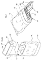
- Figure 1 is a perspective view of the dispenser pack, disposed in a prone position with the dispensing element in its open position.
- Figure 1A is perspective view of the dispenser pack of Figure 1 in an erect position, with the dispensing element in its closed position and with the dispensing head and the limp container shown detached from each other.
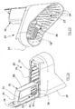
- Figure 2A is an enlarged detail of the dispensing head of Figure 1A (the limp container having been removed).
- Figure 2B is a perspective view of Figure 2A from a different viewpoint.
- Figure 3 is a section through the rigid head, with the dispensing element in its open position.
- Figure 3A is a section such as Figure 3, with the dispensing element in its closed position.
- Figure 4 is a section on the plane IV-IV of Figure 3, with the pack disposed in the position for releasing an article to the outside.
- Figure 5 shows an article of the type suitable to be contained in the pack of the invention.
- Figures 1 and 1A show a dispenser pack according to the invention, having a rigid dispensing head 20, in particular made of sufficiently rigid synthetic resin, and a limp container 10 of yieldable material to contain loose articles 8, and having an upper mouth 11 closed by the dispensing head 20, to which the edge 12 of the mouth 11 adheres and is rigidly joined in a sealed manner.
- the limp container 10 is preferably made of a thin film of foldable yieldable polyethylene shaped as a limp tube (possibly made by folding a sheet back on itself and bonding the side edges together) with its upper end open to define the mouth 11 and its opposite lower end closed along a sealing edge 13;
- the dispensing head 20 is preferably also made of the same material or of polypropylene.
- the edge 12 of the mouth adheres to the outer surface of a lateral wall 25 of the dispensing head 20 and is joined rigidly thereto preferably by hot bonding, or by glue, or by other known methods.
- the head 20 possesses an outlet 22 for the articles 8, means for dispensing the articles to the outside in a controlled manner, and means for closing the outlet 22.
- the size of the pack decreases on the basis of the quantity of articles contained; for example when the articles are relatively few in number, the limp container folds about itself so that when placed in a pocket, a bag or other similar storage space, its overall size reduces correspondingly.
- this behavior means that the articles remain amassed tightly against each other and, even when the pack is shaken for example because lying in a pocket or bag in movement, it produces no substantial noise.
- this is typically suitable for containing and dispensing articles 8 having a shape in which the main dimensions along the three Cartesian axes X, Y and Z are different, such as in the case of the tablet shown in Figure 5, which is of generally parallelepiped form with rounded corners, in which the length along the X axis is the maximum dimension and the width, i.e. the dimension along the Y axis, is less than the length but greater than the thickness, i.e. the dimension along the Z axis.
- the dispensing head 20 comprises an outer shell composed substantially of the skirt-shaped outer lateral wall 25 and an upper wall 26, and a dispensing element 30 having a dispensing cavity 31 able to receive, virtually as an exact fit with small clearance, one article 8 at a time disposed in predetermined orientation.
- the dispensing element 30 is of roughly parallelepiped shape with a major axis X' and two minor axes, its cavity 31 being closed by two major walls 33 located on one of the two major faces, by a minor wall 34 located on one of the two minor faces, and by two intermediate walls 35 located on the two faces of intermediate size.
- One of the two major walls 33 is virtually completely open to define the outlet aperture 22 enabling the article to leave the cavity.
- an insertion corridor 23 substantially coaxial with the major axis of the dispensing cavity 31 when this is in its open position, and communicating therewith via a passage section 37 positioned in the plane perpendicular to the major axis of the cavity 31, the corridor being arranged to convey, one at a time, the articles disposed loose in the container 10, firstly into the corridor 23 and from there into the dispensing cavity 31.
- the cross-section of the corridor 23 has dimensions substantially equal to the cross-section of the cavity 31, to enable an article 8 to pass only if disposed with a predetermined orientation determined by the shape of the cavity 31, i.e. disposed with is major axis substantially coinciding with the axis of the corridor 23.
- the surfaces of the corridor 23 are substantially coplanar with the lateral faces of the cavity 31.
- the corridor in its initial portion the corridor has a wider shape, which narrows until it reaches a constant dimension which it maintains as far as the passage section 37.
- the surfaces of the corridor 23 are not defined by smooth walls, but instead by the inner edges, all parallel to each other and to the axis of the corridor 23, of a plurality of fins 24 which, joined to the inner surface of the lateral wall 25, project inwards; these fins 24 are sufficiently close together, in relation to the dimensions of the articles 8, to define with the envelope defined by their inner edges a slide and guide surface for the articles.
- the dispensing element 30 is able to assume two different stable positions: an "open position” in which it projects outwards from the outer shell of the dispensing head 20 and the outlet aperture 22 lies external to the pack in order to dispense one article 8 at a time to the outside, and a "closed position” in which the outlet aperture lies inside the inner chamber.
- the dispensing element 30 is able to rotate about one of its minor corners, that situated on the outer side of the upper wall 26, and is joined to, and integral with, the head 20 by a thin strip of material defining a hinge 36;
- the dispensing element 30 can rotate through approximately 90 degrees about the hinge 36, to assume the open position (see Figures 1, 2A, 3 and 4) or the closed position (see Figures 1 A and 3A).
- the major axis X' of the cavity 31 substantially coincides with the axis of the insertion corridor 23.
- the dispensing element 30 penetrates into the head 20 by passing through an aperture 27 provided in the upper wall 26, to be housed to the side of the corridor 23 and partly within it; when in its closed position, one of the walls 35 of the dispensing element 30 exactly closes the aperture 27.
- an elastically deformable flat spring 28 is provided which undergoes elastic deformation following rotation of the element 30.
- the flat spring 28 is composed of a front portion 28' which, when the dispensing element 30 is in its open position, is disposed virtually parallel to the axis of the corridor 23 (see Figure 3), and of a rear portion virtually parallel to the upper wall 26.
- the flat spring 28 is in geometrical relationship with the dispensing element 30 such that its two flat portions are deformed to a maximum extent when the dispensing element 30 is in an intermediate position between the open position and the closed position, and vice versa are deformed to a minimum extent when the element 30 is in one of its two end positions, which are consequently stable because of the action of the spring 28.
- the front portion 28' of the spring also defines a side of the insertion corridor 23 when the dispensing element 30 is in its open position.
- the correct manual operations involved in dispensing one article at a time consist firstly of holding the pack in a prone position with the dispensing element 30 open, the aperture 22 facing upwards and the head 20 lower than the container 10 (as shown in Figure 1), to enable the articles 8 to enter the corridor 23 one at a time by gravity, and then to slide along the surfaces of the corridor and reach the cavity 31.
- the projection 39 lies on the top of the corridor 23 and hence, as the articles slide on the lower surface of the corridor and as there is a slight difference between the dimensions of the articles and those of the passage section 37, the projection 39 does not touch the articles and there is no obstacle to their passage through the section.
- the pack When an article 8 is positioned in the cavity 31, it can be taken from the cavity by the fingers or, more comfortably, the pack can be inverted through 180 degrees about the axis X' so that the aperture 22 faces downwards and the article 8 falls by gravity from the cavity 31 (see Figure 4).
- the projection 39 plays an important role as it is in contact with the front end of the article located upstream of the passage section 37 and hence holds it at rest to prevent it being able to reach the cavity 31 and also escape from the cavity 22.
Landscapes
- Engineering & Computer Science (AREA)
- Mechanical Engineering (AREA)
- Medical Preparation Storing Or Oral Administration Devices (AREA)
- Packages (AREA)
Abstract
The dispenser pack comprises: for containing the loose articles, a limp
container (10) of yieldable material having a mouth (11) and a rigid
dispensing head (20) which is joined to the container mouth (11) to close
the mouth (11) and has an outlet (22) for the articles, means for
dispensing the articles to the outside in a controlled manner, and means
for closing said outlet (22).
According to another aspect of the invention, the dispensing head (20) comprises a dispensing element (30) arranged to project outwards from the head and having a dispensing cavity (31) able to receive, virtually as an exact fit, one article (8) at a time disposed with predetermined orientation, said cavity (31) having, provided in one side, an outlet aperture enabling the article (8) to leave the cavity (31), and an insertion corridor (23) substantially coaxial with the major axis of the dispensing cavity (31) and communicating therewith via a passage section (37) located in the plane perpendicular to said major axis of the cavity (31), and which is arranged to convey the articles disposed loose in the container (10) one at a time into the corridor (23), and from there into the dispensing cavity (31) in a predetermined orientation.
According to another aspect of the invention, the dispensing head (20) comprises a dispensing element (30) arranged to project outwards from the head and having a dispensing cavity (31) able to receive, virtually as an exact fit, one article (8) at a time disposed with predetermined orientation, said cavity (31) having, provided in one side, an outlet aperture enabling the article (8) to leave the cavity (31), and an insertion corridor (23) substantially coaxial with the major axis of the dispensing cavity (31) and communicating therewith via a passage section (37) located in the plane perpendicular to said major axis of the cavity (31), and which is arranged to convey the articles disposed loose in the container (10) one at a time into the corridor (23), and from there into the dispensing cavity (31) in a predetermined orientation.
Description
- The present invention relates to a dispenser pack for small solid articles for consumption, in particular sweets, pills and the like.
- Numerous different dispenser packs for sweets, pills and the like are known, comprising a rigid container having, in the vicinity of its head, means for dispensing the articles to the outside in a controlled manner, and means for closing the dispensing outlet.
- These packs are able to dispense the contained articles hygienically, as they are able to dispense them one at a time without it being necessary to return part of the dispensed articles to the container after having touched them with the hand.
- However, a drawback of these dispenser packs is that being rigid, and mostly of synthetic resin, they maintain their original dimensions not only when completely filled with articles, but even when they contain only one, hence occupying a uselessly large space and creating a corresponding obstruction, particularly in the consumer's pocket.
- Another drawback is that if the articles themselves are rigid, these packs are rather noisy because of collisions between the articles and between these and the inner walls of the container when the pack is shaken, as is typically the case if the pack lies in a moving consumers pocket or bag.
- A first object of the invention is to overcome these and further drawbacks. To this end, the dispenser pack according to the invention comprises, for containing the loose articles, a limp container of yieldable material having a mouth and a rigid dispensing head which is joined to the container mouth to close the mouth, and has an outlet for the articles, means for dispensing the articles to the outside in a controlled manner, and means for closing said outlet.
- Preferably, the foldable container is in the form of a limp tube having one end closed on itself and the opposite end open to define the container mouth, which is closed by the rigid head to which the edge of the end is fixed.
- Another problem connected with known dispensers is that in dispensing the articles in a controlled manner one at a time, intrinsic difficulties arise in terms of their shape when this is such that the main dimensions along the three Cartesian axes X, Y and Z are different, such as in the case of the tablet shown in Figure 5, which has a generally parallelepiped shape with rounded corners, in which the length along the X axis is the maximum dimension, the dimension along the Y axis being less than the length but greater than the thickness, i.e. the dimension along the Z axis.
- Another object of the invention is to overcome this and other technical problems.
- To this end, the dispenser pack of the invention comprises a dispensing element to project outwards from the head and having a dispensing cavity able to receive, virtually as an exact fit, one article at a time disposed with predetermined orientation, said cavity having, in one side, an outlet aperture to enable the article to leave the cavity, and a insertion corridor substantially coaxial with the major axis of the dispensing cavity and communicating therewith via a passage section located in the plane perpendicular to the major axis of the cavity, which corridor is arranged to convey into the corridor, one at a time, the articles disposed loose in the container, and from the corridor into the dispensing cavity in a predetermined orientation.
- Preferably, the dispenser element is arranged to assume two different stable positions: an open position in which it projects outwards from the dispensing head and the outlet aperture is positioned external to the inner chamber, to dispense to the outside one article at a time, and a closed position in which the outlet aperture is enclosed in the interior of the inner chamber.
- Preferably, said outlet aperture is positioned in a lateral wall of the dispensing element coplanar with a side of the insertion corridor, at the passage section of the insertion corridor there being positioned a projection which projects slightly towards the interior of the section starting from the said wall in which the outlet aperture is located, to halt the travel, towards the dispensing cavity, of an article which rests on that surface of the insertion corridor coplanar with the wall in which the outlet aperture is located, but to allow passage of the same article when resting on the opposite surface of the insertion corridor.
- The invention is described in detail hereinafter with the aid of the accompanying figures which illustrate one embodiment thereof by way of non-limiting example.
- Figure 1 is a perspective view of the dispenser pack, disposed in a prone position with the dispensing element in its open position.
- Figure 1A is perspective view of the dispenser pack of Figure 1 in an erect position, with the dispensing element in its closed position and with the dispensing head and the limp container shown detached from each other.
- Figure 2A is an enlarged detail of the dispensing head of Figure 1A (the limp container having been removed).
- Figure 2B is a perspective view of Figure 2A from a different viewpoint.
- Figure 3 is a section through the rigid head, with the dispensing element in its open position.
- Figure 3A is a section such as Figure 3, with the dispensing element in its closed position.
- Figure 4 is a section on the plane IV-IV of Figure 3, with the pack disposed in the position for releasing an article to the outside.
- Figure 5 shows an article of the type suitable to be contained in the pack of the invention.
- Figures 1 and 1A show a dispenser pack according to the invention, having a rigid dispensing
head 20, in particular made of sufficiently rigid synthetic resin, and alimp container 10 of yieldable material to containloose articles 8, and having anupper mouth 11 closed by the dispensinghead 20, to which theedge 12 of themouth 11 adheres and is rigidly joined in a sealed manner. - The
limp container 10 is preferably made of a thin film of foldable yieldable polyethylene shaped as a limp tube (possibly made by folding a sheet back on itself and bonding the side edges together) with its upper end open to define themouth 11 and its opposite lower end closed along asealing edge 13; the dispensinghead 20 is preferably also made of the same material or of polypropylene. Theedge 12 of the mouth adheres to the outer surface of alateral wall 25 of the dispensinghead 20 and is joined rigidly thereto preferably by hot bonding, or by glue, or by other known methods. - The
head 20 possesses anoutlet 22 for thearticles 8, means for dispensing the articles to the outside in a controlled manner, and means for closing theoutlet 22. - By virtue of the invention, the size of the pack decreases on the basis of the quantity of articles contained; for example when the articles are relatively few in number, the limp container folds about itself so that when placed in a pocket, a bag or other similar storage space, its overall size reduces correspondingly.
- Moreover, this behavior means that the articles remain amassed tightly against each other and, even when the pack is shaken for example because lying in a pocket or bag in movement, it produces no substantial noise.
- According to a different aspect of the invention, this is typically suitable for containing and dispensing
articles 8 having a shape in which the main dimensions along the three Cartesian axes X, Y and Z are different, such as in the case of the tablet shown in Figure 5, which is of generally parallelepiped form with rounded corners, in which the length along the X axis is the maximum dimension and the width, i.e. the dimension along the Y axis, is less than the length but greater than the thickness, i.e. the dimension along the Z axis. - The dispensing
head 20 comprises an outer shell composed substantially of the skirt-shaped outerlateral wall 25 and anupper wall 26, and a dispensingelement 30 having a dispensingcavity 31 able to receive, virtually as an exact fit with small clearance, onearticle 8 at a time disposed in predetermined orientation. The dispensingelement 30 is of roughly parallelepiped shape with a major axis X' and two minor axes, itscavity 31 being closed by twomajor walls 33 located on one of the two major faces, by aminor wall 34 located on one of the two minor faces, and by twointermediate walls 35 located on the two faces of intermediate size. One of the twomajor walls 33 is virtually completely open to define theoutlet aperture 22 enabling the article to leave the cavity. - Within the internal chamber of the dispenser pack there is positioned an
insertion corridor 23, substantially coaxial with the major axis of the dispensingcavity 31 when this is in its open position, and communicating therewith via apassage section 37 positioned in the plane perpendicular to the major axis of thecavity 31, the corridor being arranged to convey, one at a time, the articles disposed loose in thecontainer 10, firstly into thecorridor 23 and from there into the dispensingcavity 31. - In its final part, i.e. in proximity to the
passage section 37, the cross-section of thecorridor 23 has dimensions substantially equal to the cross-section of thecavity 31, to enable anarticle 8 to pass only if disposed with a predetermined orientation determined by the shape of thecavity 31, i.e. disposed with is major axis substantially coinciding with the axis of thecorridor 23. In addition the surfaces of thecorridor 23 are substantially coplanar with the lateral faces of thecavity 31. In contrast, in its initial portion the corridor has a wider shape, which narrows until it reaches a constant dimension which it maintains as far as thepassage section 37. - In particular, in the embodiment shown in the figures, the surfaces of the
corridor 23 are not defined by smooth walls, but instead by the inner edges, all parallel to each other and to the axis of thecorridor 23, of a plurality offins 24 which, joined to the inner surface of thelateral wall 25, project inwards; thesefins 24 are sufficiently close together, in relation to the dimensions of thearticles 8, to define with the envelope defined by their inner edges a slide and guide surface for the articles. - The dispensing
element 30 is able to assume two different stable positions: an "open position" in which it projects outwards from the outer shell of the dispensinghead 20 and theoutlet aperture 22 lies external to the pack in order to dispense onearticle 8 at a time to the outside, and a "closed position" in which the outlet aperture lies inside the inner chamber. The dispensingelement 30 is able to rotate about one of its minor corners, that situated on the outer side of theupper wall 26, and is joined to, and integral with, thehead 20 by a thin strip of material defining ahinge 36; The dispensingelement 30 can rotate through approximately 90 degrees about thehinge 36, to assume the open position (see Figures 1, 2A, 3 and 4) or the closed position (see Figures 1 A and 3A). - When the dispensing
element 30 is in its open position, the major axis X' of thecavity 31 substantially coincides with the axis of theinsertion corridor 23. When moved into its closed position, the dispensingelement 30 penetrates into thehead 20 by passing through anaperture 27 provided in theupper wall 26, to be housed to the side of thecorridor 23 and partly within it; when in its closed position, one of thewalls 35 of the dispensingelement 30 exactly closes theaperture 27. - To maintain the dispensing
element 30 in its closed or alternatively open position, an elastically deformableflat spring 28 is provided which undergoes elastic deformation following rotation of theelement 30. Theflat spring 28 is composed of a front portion 28' which, when the dispensingelement 30 is in its open position, is disposed virtually parallel to the axis of the corridor 23 (see Figure 3), and of a rear portion virtually parallel to theupper wall 26. - The
flat spring 28 is in geometrical relationship with the dispensingelement 30 such that its two flat portions are deformed to a maximum extent when the dispensingelement 30 is in an intermediate position between the open position and the closed position, and vice versa are deformed to a minimum extent when theelement 30 is in one of its two end positions, which are consequently stable because of the action of thespring 28. - The front portion 28' of the spring also defines a side of the
insertion corridor 23 when the dispensingelement 30 is in its open position. - At the passage section of the
insertion corridor 23, on the same side as theoutlet aperture 22, there is aprojection 39 which projects slightly towards the interior of the section, to halt the travel, towards the dispensingcavity 31, of an article resting on that surface of the insertion corridor which is coplanar with the wall where theoutlet aperture 22 is positioned, whereas it enables the same article to pass if resting on the opposite surface of theinsertion corridor 23. - In detail, the correct manual operations involved in dispensing one article at a time consist firstly of holding the pack in a prone position with the dispensing
element 30 open, theaperture 22 facing upwards and thehead 20 lower than the container 10 (as shown in Figure 1), to enable thearticles 8 to enter thecorridor 23 one at a time by gravity, and then to slide along the surfaces of the corridor and reach thecavity 31. In this state, theprojection 39 lies on the top of thecorridor 23 and hence, as the articles slide on the lower surface of the corridor and as there is a slight difference between the dimensions of the articles and those of thepassage section 37, theprojection 39 does not touch the articles and there is no obstacle to their passage through the section. - When an
article 8 is positioned in thecavity 31, it can be taken from the cavity by the fingers or, more comfortably, the pack can be inverted through 180 degrees about the axis X' so that theaperture 22 faces downwards and thearticle 8 falls by gravity from the cavity 31 (see Figure 4). In this stage theprojection 39 plays an important role as it is in contact with the front end of the article located upstream of thepassage section 37 and hence holds it at rest to prevent it being able to reach thecavity 31 and also escape from thecavity 22. - Hence only one article is dispensed each time the pack is inverted, as is required.
- Numerous modifications of a practical and applicational nature can be made to the invention, but without leaving the scope of the inventive idea as claimed below.
Claims (7)
- A dispenser pack for small solid articles for consumption, in particular sweets, pills and the like, characterized by comprising:for containing the loose articles, a limp container (10) of yieldable material having a mouth (11) anda rigid dispensing head (20) joined to the container mouth (11) to close the mouth (11) and having an outlet (22) for the articles, means for dispensing the articles to the outside in a controlled manner, and means for closing said outlet (22).
- A dispenser pack as claimed in claim 1, characterized in that the limp container (10) is in the form of a limp tube having one end closed on itself and its opposite end open to define the container mouth (11), which is closed by the dispensing head (20) to which the edge (12) of the end is fixed.
- A dispenser pack for small solid articles for consumption, the main dimensions along the three Cartesian axes of which are different, comprising a container (10) for containing the loose articles, and a dispensing head (20) having an outlet (22) for the articles, means for dispensing the articles to the outside in a controlled manner, and means for closing said outlet (22), characterized by comprising a dispensing element (30) arranged to project outwards from the dispensing head (20) and having a dispensing cavity (31) able to receive, virtually as an exact fit, one article (8) at a time disposed with predetermined orientation, said cavity (31) having, provided in one side, an outlet aperture enabling the article (8) to leave the cavity (31), and an insertion corridor (23) substantially coaxial with the major axis of the dispensing cavity (31) and communicating therewith via a passage section (37) located in the plane perpendicular to said major axis of the cavity (31) and arranged to convey the articles disposed loose in the container (10) one at a time into the corridor (23), and from there into the dispensing cavity (31) in a predetermined orientation.
- A dispenser pack as claimed in claim 3, characterized in that said dispenser element (30) is arranged to assume two different stable positions: an open position in which it projects outwards from the dispensing head (20) and the outlet aperture (22) is positioned external to the chamber of the container (10), to dispense to the outside one article at a time, and a closed position in which the outlet aperture (22) is enclosed in the interior of the container (10).
- A dispenser pack as claimed in claim 4, characterized in that said dispensing element (30) is able to rotate about a hinge (36) to assume said open and closed positions.
- A dispenser pack as claimed in claim 5, characterized by comprising an elastic flat spring (28) which undergoes elastic deformation following rotation of the dispensing element (30), to maintain the element (30) in its closed or alternatively open position.
- A dispenser pack as claimed in claim 3, characterized in that at the passage section of the insertion corridor (23), on the same side as the outlet aperture (22), there is provided a projection (39) which projects slightly towards the interior of the section (39), to halt the travel, towards the dispensing cavity (31), of an article resting on that surface of the insertion corridor (23) which is coplanar with the wall (33) where the outlet aperture (22) is positioned, whereas it enables the same article to pass if resting on the opposite surface of the insertion corridor (23).
Applications Claiming Priority (2)
| Application Number | Priority Date | Filing Date | Title |
|---|---|---|---|
| IT000027A ITRE20030027A1 (en) | 2003-03-14 | 2003-03-14 | "PACKAGE-DISPENSER FOR SMALL SOLID CONSUMABLES, |
| ITRE20030027 | 2003-03-14 |
Publications (1)
| Publication Number | Publication Date |
|---|---|
| EP1457433A2 true EP1457433A2 (en) | 2004-09-15 |
Family
ID=29267144
Family Applications (1)
| Application Number | Title | Priority Date | Filing Date |
|---|---|---|---|
| EP04075761A Withdrawn EP1457433A2 (en) | 2003-03-14 | 2004-03-09 | Dispenser pack for small solid articles for consumption, in particular sweets, pills and the like |
Country Status (3)
| Country | Link |
|---|---|
| US (1) | US20040178212A1 (en) |
| EP (1) | EP1457433A2 (en) |
| IT (1) | ITRE20030027A1 (en) |
Families Citing this family (1)
| Publication number | Priority date | Publication date | Assignee | Title |
|---|---|---|---|---|
| JP2009519871A (en) * | 2005-12-16 | 2009-05-21 | ミードウエストベコ・コーポレーション | Pediatric safety dispenser |
Family Cites Families (4)
| Publication number | Priority date | Publication date | Assignee | Title |
|---|---|---|---|---|
| US2086296A (en) * | 1937-01-08 | 1937-07-06 | Gilbert Charles Emile | Box unloading device |
| US2472871A (en) * | 1946-04-17 | 1949-06-14 | Marshall I Williamson | Dispensing container |
| US5484089A (en) * | 1994-11-23 | 1996-01-16 | Picerno; Virginia L. | Pill bottle and dispensing cap combination |
| US5860742A (en) * | 1997-08-28 | 1999-01-19 | Faircloth, Jr.; J. Wade | Flexible bag dispenser |
-
2003
- 2003-03-14 IT IT000027A patent/ITRE20030027A1/en unknown
-
2004
- 2004-03-09 EP EP04075761A patent/EP1457433A2/en not_active Withdrawn
- 2004-03-12 US US10/798,866 patent/US20040178212A1/en not_active Abandoned
Also Published As
| Publication number | Publication date |
|---|---|
| US20040178212A1 (en) | 2004-09-16 |
| ITRE20030027A1 (en) | 2004-09-15 |
| ITRE20030027A0 (en) | 2003-03-14 |
Similar Documents
| Publication | Publication Date | Title |
|---|---|---|
| US20080029528A1 (en) | Storage and dispenser box for small articles | |
| RU2288153C2 (en) | Package for disposable items | |
| US2917162A (en) | Pill dispensing unit | |
| CN107000889A (en) | Shoulder bag with lid lifting member | |
| US5431304A (en) | Liquid and particulate product dispenser | |
| JP7816741B2 (en) | Sanitary product containers and sanitary product container sets | |
| CN103958358A (en) | box packaging | |
| CN101146723A (en) | Combined Hinged Lid Cigarette Pack | |
| US2472871A (en) | Dispensing container | |
| US6892877B2 (en) | Dispensing container | |
| WO2018183239A1 (en) | Child-resistant dispenser, method of dispensing a unit of product from a dispenser | |
| US20040178212A1 (en) | Dispenser pack for small solid articles for consumption, in particular sweets, pills and the like | |
| EP3710369B1 (en) | Container for consumer goods including dispensing means | |
| US20090008286A1 (en) | Dispenser with a Spout | |
| US2475738A (en) | Pill dispenser | |
| US8181772B2 (en) | Dispenser with corner latches | |
| US20050236419A1 (en) | Comestible product dispensers and methods of making and using same | |
| CN104159826A (en) | Pocket-sized packaging for small products | |
| JP5123315B2 (en) | container | |
| JP2002104546A (en) | Dispensing device | |
| US6070759A (en) | Container with dispensing feature in overcap | |
| WO2006123228A1 (en) | Container for delivering doses of a particulate product | |
| JP4460114B2 (en) | Double container | |
| ITRM960195U1 (en) | CONTAINER-DOSER FOR BULK PRODUCTS, IN PARTICULAR GRANULARS AND POWDER | |
| MX2007008536A (en) | A pocket-size packet of confectionery products. |
Legal Events
| Date | Code | Title | Description |
|---|---|---|---|
| PUAI | Public reference made under article 153(3) epc to a published international application that has entered the european phase |
Free format text: ORIGINAL CODE: 0009012 |
|
| AK | Designated contracting states |
Kind code of ref document: A2 Designated state(s): AT BE BG CH CY CZ DE DK EE ES FI FR GB GR HU IE IT LI LU MC NL PL PT RO SE SI SK TR |
|
| AX | Request for extension of the european patent |
Extension state: AL HR LT LV MK |
|
| STAA | Information on the status of an ep patent application or granted ep patent |
Free format text: STATUS: THE APPLICATION IS DEEMED TO BE WITHDRAWN |
|
| 18D | Application deemed to be withdrawn |
Effective date: 20061002 |