EP1457422A2 - Method of dispensing particles, a container filled with particles in accordance with the same method, and a particle filling line arranged to fill containers in accordance with the same method - Google Patents
Method of dispensing particles, a container filled with particles in accordance with the same method, and a particle filling line arranged to fill containers in accordance with the same method Download PDFInfo
- Publication number
- EP1457422A2 EP1457422A2 EP04005325A EP04005325A EP1457422A2 EP 1457422 A2 EP1457422 A2 EP 1457422A2 EP 04005325 A EP04005325 A EP 04005325A EP 04005325 A EP04005325 A EP 04005325A EP 1457422 A2 EP1457422 A2 EP 1457422A2
- Authority
- EP
- European Patent Office
- Prior art keywords
- conduit
- particles
- outlet
- hollow
- porous tube
- Prior art date
- Legal status (The legal status is an assumption and is not a legal conclusion. Google has not performed a legal analysis and makes no representation as to the accuracy of the status listed.)
- Granted
Links
Images

Classifications
-
- B—PERFORMING OPERATIONS; TRANSPORTING
- B65—CONVEYING; PACKING; STORING; HANDLING THIN OR FILAMENTARY MATERIAL
- B65B—MACHINES, APPARATUS OR DEVICES FOR, OR METHODS OF, PACKAGING ARTICLES OR MATERIALS; UNPACKING
- B65B1/00—Packaging fluent solid material, e.g. powders, granular or loose fibrous material, loose masses of small articles, in individual containers or receptacles, e.g. bags, sacks, boxes, cartons, cans, or jars
- B65B1/20—Reducing volume of filled material
- B65B1/26—Reducing volume of filled material by pneumatic means, e.g. suction
-
- B—PERFORMING OPERATIONS; TRANSPORTING
- B65—CONVEYING; PACKING; STORING; HANDLING THIN OR FILAMENTARY MATERIAL
- B65B—MACHINES, APPARATUS OR DEVICES FOR, OR METHODS OF, PACKAGING ARTICLES OR MATERIALS; UNPACKING
- B65B39/00—Nozzles, funnels or guides for introducing articles or materials into containers or wrappers
- B65B39/04—Nozzles, funnels or guides for introducing articles or materials into containers or wrappers having air-escape, or air-withdrawal, passages
Definitions
- a method of dispensing particles utilizing apparatus comprising a vertically-oriented conduit having a conduit hollow, a conduit top and a conduit bottom, the conduit bottom defining an outlet, the conduit arranged so that particles supplied to the conduit top flow through the outlet, the method comprising (a) filling the conduit hollow with particles, the particles including a particle spacing air; (b) reducing the particle spacing air; and (c) flowing the particles through the outlet.
- a container at least partly filled with particles in accordance with a method, the method utilizing apparatus comprising a vertically-oriented conduit having a conduit hollow, a conduit top and a conduit bottom, the conduit bottom defining an outlet, the conduit arranged so that particles supplied to the conduit top flow through the outlet, the method comprising (a) filling the conduit hollow with particles, the particles including a particle spacing air; (b) reducing the particle spacing air; and (c) flowing the particles through the outlet to be received in the container.
- the conduit has a porous tube substantially horizontally-oriented in the conduit hollow, the conduit hollow filled with particles so that particles substantially surround the porous tube, the particle spacing air being reduced by applying a vacuum pressure to the porous tube.
- the porous tube forms a toroid-shaped ring.
- the particles comprise toner particles
- the conduit comprises a toner filler hopper and the container comprises a toner cartridge.
- the porous tube is comprised of an ultra-high molecular weight polyethylene material.
- the vacuum pressure is applied to the porous tube at a pressure of about 3 pounds per square inch.
- a particle filling line comprising a vertically-oriented conduit, the conduit having a conduit hollow, a conduit top and a conduit bottom, the conduit bottom defining an outlet, the conduit arranged so that particles supplied to the conduit top flow through the outlet, the particle filling line arranged to fill one or more containers with particles in accordance with a method comprising (a) filling the conduit hollow with particles, the particles including a particle spacing air; (b) reducing the particle spacing air; and (c) flowing the particles through the outlet to be received in one or more containers disposed on an included movable conveyor belt.
- the particle spacing air is reduced by means of a porous tube substantially horizontally-oriented in the conduit hollow and coupled to a vacuum source.
- a method of dispensing particles utilizing apparatus comprising a vertically-oriented conduit having a conduit hollow, a conduit top and a conduit bottom, the conduit bottom defining an outlet, the conduit arranged so that particles supplied to the conduit top flow through the outlet, a porous tube substantially horizontally-oriented in the conduit hollow, the method comprising (a) filling the conduit hollow with particles so that particles substantially surround the porous tube; (b) applying a vacuum pressure to the porous tube; and (c) flowing the particles through the outlet.
- the porous tube forms a toroid-shaped ring.
- the method comprises providing at least one container to receive particles from the outlet.
- the particles comprises toner particles and the conduit comprises a toner filler hopper.
- the porous tube is comprised of an ultra-high molecular weight polyethylene material.
- the vacuum pressure is applied to the porous tube at a pressure of about 3 pounds per square inch.
- a container at least partly filled with particles in accordance with a method, the method utilizing apparatus comprising a vertically-oriented conduit having a conduit hollow, a conduit top and a conduit bottom, the conduit bottom defining an outlet, the conduit arranged so that particles supplied to the conduit top flow through the outlet, a porous tube substantially horizontally-oriented in the conduit hollow, the method comprising (a) filling the conduit hollow with particles so that particles substantially surround the porous tube; (b) applying a vacuum pressure to the porous tube; and (c) flowing the particles through the outlet to be received in the container.
- a particle filling line comprising a vertically-oriented conduit, the conduit having a conduit hollow, a conduit top and a conduit bottom, the conduit bottom defining an outlet, the conduit arranged so that particles supplied to the conduit top flow through the outlet, a porous tube substantially horizontally-oriented in the conduit hollow, the particle filling line arranged to fill one or more containers with particles in accordance with a method comprising (a) filling the conduit hollow with particles so that particles substantially surround the porous tube; (b) applying a vacuum pressure to the porous tube; and (c) flowing the particles through the outlet to be received in one or more containers disposed on an included movable conveyor belt.
- a particle filling line comprises a vertical conduit that is arranged to dispense particles to one or more containers that are disposed on an included movable conveyor belt.
- the conduit includes a conduit hollow, a conduit top and a conduit bottom that defines an outlet. Particles supplied to the conduit top flow through the outlet to fill the containers.
- the conduit is filled with particles.
- the particles include a particle spacing air. The particle spacing air is reduced by means of a porous tube that is fixed in the conduit hollow and coupled to a vacuum source. After reducing the particle spacing air, the particles flow through the outlet to be received in the containers.
- the porous tube is substantially horizontally-oriented.
- the porous tube forms a toroid-shaped ring.
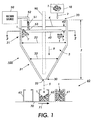
- a particle filling line comprising a vertically-oriented conduit 100.
- the conduit 100 includes a conduit hollow 3, a conduit top 20 and a conduit bottom 30, with a conduit height 7 between the conduit top 20 and the conduit bottom 30.
- the conduit bottom 30 defines an outlet 33.
- a particle source 10 is arranged to supply particles 1 to the conduit top 20.
- Particles 1 being supplied to the conduit 100 are depicted by the reference number 2.
- the particles 1 thereafter flow in a downward particle flow direction 9 to the conduit bottom 30 to then be dispensed through the outlet 33.
- Particles being dispensed from the conduit 100 are depicted by the reference number 5.
- the particle filling line is arranged to fill one or more containers 60 with particles 1.
- the conduit 100 comprises a cylindrical-shaped portion 21 proximate to the conduit top 20, with a corresponding cylindrical portion inner diameter 22 that is uniform along the height 7 in the particle flow direction 9. Also, the conduit 100 further comprises a conical-shaped portion 31 proximate to the conduit bottom 30 with a corresponding cylindrical portion inner diameter 32 that becomes increasingly narrower along the height 7 in the particle flow direction 9.
- the conduit 100 includes a vertically-oriented particle conveyor 90 (shown in broken lines) disposed at least partly in the conduit hollow 3.
- the particle conveyor 90 is substantially centered with the conduit vertical axis 101.
- the conduit hollow 3 is filled 2 with particles 1 to a particle supply level 4, the particles in the conduit hollow 3 below the particle supply level 4 including a particle spacing air 1'.
- the particle spacing air 1' is then reduced.
- the particles 1 flow 5 through the outlet 33 to be received in one or more containers 60 disposed on an included conveyor belt 70 that is arranged to move in a direction 71.
- the particle spacing air 1' is reduced by a porous tube 40 that is fixed in the conduit hollow 3.
- the porous tube 40 has a substantially horizontal orientation.
- the filling 2 of the conduit hollow 3 with particles 1 results in the particles 1 substantially surrounding the porous tube 4.
- the particle supply level 4 is above the porous tube 40 by a height difference depicted in FIG. 1 by reference number 42.
- the porous tube 40 is coupled to a vacuum source 50 by means of a vacuum feed line 52.
- the flow of particle spacing air 1' from the conduit 100 to the vacuum source 50 is depicted by reference number 51.
- the vacuum source 50 applies a vacuum pressure of about 3 pounds per square inch, which pressure is equivalent to 6 inches of Mercury, or 0.2 Bars.
- the porous tube 40 forms a toroid-shaped ring that surrounds the particle conveyor 90.
- the toroid-shaped porous tube 40 is substantially centered with the conduit vertical axis 101.
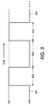
- the vacuum pressure 50 is applied to the porous tube for at least a fixed period 302 such as, for example, about 5 seconds, with the one or more containers 60 being filled during the successive period 303.
- the porous tube 40 is fixed in the hollow 3 by being suspended by vertically-oriented support wires (not shown) from above the conduit top 20.
- the porous tube 40 is supported by the vertical vacuum feed line 52 and two (2) included two millimeter (2 mm) outer diameter stainless steel weld support wires.
- Each support wire is spaced an equal radial distance from the juncture 53 of the porous tube 40 and the vacuum feed line 52.
- each support wire is radially spaced one hundred twenty (120) degrees from the juncture 53.
- Each support wire has one end wrapped tightly several times around the porous tube 40 outer diameter with the opposite end brought through a tapped hole in the conduit top 20 to hold the support wire.
- the vacuum feed line 52 connects to an end-to-end quick connect externally threaded push fitting secured to the conduit top 20 by two (2) nuts and two (2) gaskets to seal each side.
- the porous tubing material is obtained from its supplier in a standard thirty-six inch (36 ") linear length.
- the tubing is bent into a circular ring shape with each tube end inserted into a one-half inch (1/2 ") T quick connect push fitting at the porous tube and vacuum feed line juncture 53.
- the T fitting secures the tube ends to maintain the ring shape.
- the T fitting provides the coupling juncture 53 for the vacuum feed line 52 to thus maintain the integrity of the vacuum flow of particle spacing air 51 through the porous tube 40 and the vacuum feed line 52.
- the porous tube 40 comprises an ultra-high molecular weight polyethylene material.
- Such porous tubing materials are available from various suppliers, such suppliers including Porex Technologies, 500 Bohannon Road, Fairbum, Georgia, 30312, phone number 770-964-1428, website address www.porex.com.
- the porous tube 40 comprises an inner diameter of about 1/8-inch and an outer diameter of about 1/2-inch.
- the particles 1 comprise xerographic toner particles
- the conduit 100 comprises a toner filler hopper
- the one or more containers 60 comprise toner cartridges.
- the particles 1 comprise non-toner particles.
- the conduit height 7 is about 28 inches and the particle supply level 4 and porous tube 40 height difference 42 is from 1 to 3 inches.
- the conduit cylindrical portion inner diameter 22 is about 22 inches and the porous tube 40 outer diameter 41 is about 12 inches.
- the conduit 100 is similar or identical to any of the following apparatus counterparts: the hopper 12 in the Wegman '821 patent; the powder filling assisting apparatus 10 in the Wegman '025 patent; the hopper 12 in the Wegman '278 patent; the hopper 14 in the Wegman '764 patent; and the hopper 14 in the Wegman '259 patent.
- the particle conveyor 90 is similar or identical to any of the following apparatus counterparts: the screw auger 22 in the Wegman '821 patent; the spiral conveyor or auger 40 in the Wegman '025 patent; the auger 104 in the Wegman '278 patent; the spiral conveyor or auger 40 in the Wegman '764 patent; and the spiral conveyor or auger 40 in the Wegman '259 patent.
- the one or more containers 60 are similar or identical to any of the following apparatus counterparts: the toner bottle 36 described at col. 9, lines 13-14 in the Wegman '821 patent; the container 16 in the Wegman '025 patent; the container 116 in the Wegman '278 patent; the container 116 in the Wegman '764 patent; and the container 16 in the Wegman '259 patent.
- the conveyor belt 70 is similar or identical to any of the following apparatus counterparts: the conveyor 142 in the Wegman '821 patent; the indexing conveyor 170 in the Wegman '025 patent; and the conveyor 170 in the Wegman '278 patent.
- FIG. 1 depicted in FIG. 1 comprising a vertically-oriented conduit 100 having a conduit hollow 3, a conduit top 20 and a conduit bottom 30, the conduit bottom 30 defining an outlet 33, the conduit 100 arranged so that particles 1 supplied to the conduit top 20 flow through the outlet 33, the method comprising (a) filling 2 the conduit hollow 3 with particles 1, the particles 1 including a particle spacing air 1'; (b) reducing the particle spacing air 1' (based on the flow 51 of particle spacing air 1'); and (c) flowing 5 the particles 1 through the outlet 33.
- FIG. 1 a container depicted in FIG. 1 by the reference number 62 that has been at least partly filled with particles 1 in accordance with a method.
- the method utilizes apparatus depicted in FIG. 1 comprising a vertically-oriented conduit 100 having a conduit hollow 3, a conduit top 20 and a conduit bottom 30, the conduit bottom 30 defining an outlet 33, the conduit 100 arranged so that particles 1 supplied to the conduit top 20 flow through the outlet 33, the method comprising (a) filling 2 the conduit hollow 3 with particles 1, the particles 1 including a particle spacing air 1'; (b) reducing the particle spacing air 1' (based on the flow 51 of particle spacing air 1'); and (c) flowing 5 the particles 1 through the outlet 33 to be received in the container 62.
- FIG. 1 a particle filling line depicted in FIG. 1 comprising a vertically-oriented conduit 100, the conduit 100 having a conduit hollow 3, a conduit top 20 and a conduit bottom 30, the conduit bottom 30 defining an outlet 33, the conduit 100 arranged so that particles 1 supplied to the conduit top 20 flow through the outlet 33, the particle filling line arranged to fill one or more containers with particles 1 in accordance with a method comprising (a) filling 2 the conduit hollow 3 with particles 1, the particles 1 including a particle spacing air 1'; (b) reducing the particle spacing air 1' (based on the flow 51 of particle spacing air 1'); and (c) flowing the particles 1 through the outlet 33 to be received 5 in one or more containers 60 disposed on an included movable conveyor belt 70.
- FIG. 1 depicts a method of dispensing particles 1 utilizing apparatus depicted in FIG. 1 comprising a vertically-oriented conduit 100 having a conduit hollow 3, a conduit top 20 and a conduit bottom 30, the conduit bottom 30 defining an outlet 33, the conduit 100 arranged so that particles 1 supplied to the conduit top 20 flow through the outlet 33, a porous tube 40 substantially horizontally-oriented in the conduit hollow 3, the method comprising (a) filling 2 the conduit hollow 3 with particles 1 so that particles 1 substantially surround the porous tube 40; (b) applying a vacuum pressure 50 to the porous tube 40; and (c) flowing 5 the particles 1 through the outlet 33.
- FIG. 1 a container depicted in FIG. 1 by the reference number 62 that has been at least partly filled with particles 1 in accordance with a method.
- the method utilizes apparatus depicted in FIG. 1 comprising a vertically-oriented conduit 100 having a conduit hollow 3, a conduit top 20 and a conduit bottom 30, the conduit bottom 30 defining an outlet 33, the conduit 100 arranged so that particles 1 supplied to the conduit top 20 flow through the outlet 33, a porous tube 40 substantially horizontally-oriented in the conduit hollow 3, the method comprising (a) filling 2 the conduit hollow 3 with particles 1 so that particles 1 substantially surround the porous tube 40; (b) applying a vacuum pressure 50 to the porous tube 40; and (c) flowing 5 the particles 1 through the outlet 33 to be received in the container 62.
- FIG. 1 a particle filling line depicted in FIG. 1 comprising a vertically-oriented conduit 100, the conduit 100 having a conduit hollow 3, a conduit top 20 and a conduit bottom 30, the conduit bottom 30 defining an outlet 33, the conduit 100 arranged so that particles 1 supplied to the conduit top 20 flow through the outlet 33, a porous tube 40 substantially horizontally-oriented in the conduit hollow 3, the particle filling line arranged to fill one or more containers with particles 1 in accordance with a method comprising (a) filling 2 the conduit hollow 3 with particles 1 so that particles 1 substantially surround the porous tube 40; (b) applying a vacuum pressure 50 to the porous tube 40; and (c) flowing the particles 1 through the outlet 33 to be received 5 in one or more containers 60 disposed on an included movable conveyor belt 70.
- the present invention results in a 50-100% increase in toner filling throughput rates by enabling consistent dense toner in the toner filler hopper 100.
- this invention increases the capacity of existing capital toner filling equipment.
- the invention uses the porous tube 40 comprising Porex (it is noted the term "Porex” is a trade mark of Porex Technologies Corporation) rods connected to an alternating vacuum source 50 to increase the toner density inside the filler hopper 100.
- the vacuum 50 is turned on while particles 1 are being supplied 2 to the hopper 100 and off while particles 1 are being dispensed 5 to the toner cartridges 60.
- the small micron size of the porous tube 40 material allows air to be pulled out of the toner particles 1 below the particle supply level 4.
- the hollow core of the tube 40 maximizes vacuum flow to the entire surface of the tube 40. The air is pulled from the toner particles in the filler hopper 100 resulting in a dense toner state that enables accurate high-speed volumetric filling.
- the Porex rods are positioned inside the upper portion of the hopper 100 to come into contact with the toner 1.
- the rods are attached to a vacuum source that is alternated on and off as depicted in FIG. 3.
- the invention is easy and low cost to retrofit on existing toner filling equipment. By enabling consistent dense toner in the filling hopper, weight control improves, and the toner fill is denser, thus allowing more toner to fit in the container and a cleaner fill.
Landscapes
- Engineering & Computer Science (AREA)
- Mechanical Engineering (AREA)
- Basic Packing Technique (AREA)
Abstract
Description
In one embodiment, the conduit has a porous tube substantially horizontally-oriented in the conduit hollow, the conduit hollow filled with particles so that particles substantially surround the porous tube, the particle spacing air being reduced by applying a vacuum pressure to the porous tube.
In a further embodiment the porous tube forms a toroid-shaped ring.
In a further embodiment the particles comprise toner particles, the conduit comprises a toner filler hopper and the container comprises a toner cartridge.
In a further embodiment the porous tube is comprised of an ultra-high molecular weight polyethylene material.
In a further embodiment the vacuum pressure is applied to the porous tube at a pressure of about 3 pounds per square inch.
In a further embodiment the particle spacing air is reduced by means of a porous tube substantially horizontally-oriented in the conduit hollow and coupled to a vacuum source.
In a fourth aspect of the invention, there is described a method of dispensing particles utilizing apparatus comprising a vertically-oriented conduit having a conduit hollow, a conduit top and a conduit bottom, the conduit bottom defining an outlet, the conduit arranged so that particles supplied to the conduit top flow through the outlet, a porous tube substantially horizontally-oriented in the conduit hollow, the method comprising (a) filling the conduit hollow with particles so that particles substantially surround the porous tube; (b) applying a vacuum pressure to the porous tube; and (c) flowing the particles through the outlet.
In a further embodiment the porous tube forms a toroid-shaped ring.
In a further embodiment the method comprises providing at least one container to receive particles from the outlet.
In a further embodiment the particles comprises toner particles and the conduit comprises a toner filler hopper.
In a further embodiment the porous tube is comprised of an ultra-high molecular weight polyethylene material.
In a further embodiment the vacuum pressure is applied to the porous tube at a pressure of about 3 pounds per square inch.
| Reference number: | Description: |
| 1 | particles |
| 1' | |
| 2 | particles being supplied to the |
| 3 | conduit hollow |
| 4 | |
| 5 | particles being dispensed from the |
| 7 | |
| 9 | flow of particles in |
| 10 | |
| 20 | conduit top |
| 21 | conduit |
| 22 | conduit cylindrical portion |
| 30 | conduit bottom |
| 31 | conduit |
| 32 | conduit conical portion |
| 33 | |
| 40 | |
| 41 | porous tube toroid-shaped ring |
| 42 | particle supply level and porous |
| 50 | |
| 51 | flow of |
| 52 | |
| 53 | porous tube and vacuum |
| 60, 61, 62, 63 | |
| 70 | |
| 71 | direction of |
| 90 | |
| 100 | |
| 101 | conduit |
| 301, 302, 303, 304, 305 | time periods |
Claims (10)
- A method of dispensing particles utilizing apparatus comprising a vertically-oriented conduit having a conduit hollow, a conduit top and a conduit bottom, the conduit bottom defining an outlet, the conduit arranged so that particles supplied to the conduit top flow through the outlet, the method comprising (a) filling the conduit hollow with particles, the particles including a particle spacing air; (b) reducing the particle spacing air; and (c) flowing the particles through the outlet.
- The method of claim 1, the conduit having a porous tube substantially horizontally-oriented in the conduit hollow, the conduit hollow filled with particles so that particles substantially surround the porous tube, the particle spacing air being reduced by applying a vacuum pressure to the porous tube.
- The method of claim 2, the porous tube forming a toroid-shaped ring.
- The method of claim 3, including providing at least one container to receive particles from the outlet.
- The method of claim 4, the particles comprising toner particles and the conduit comprising a toner filler hopper.
- The method of claim 5, the porous tube comprised of an ultra-high molecular weight polyethylene material.
- The method of claim 5, the vacuum pressure applied to the porous tube at a pressure of about 3 pounds per square inch.
- A container at least partly filled with particles in accordance with a method, the method utilizing apparatus comprising a vertically-oriented conduit having a conduit hollow, a conduit top and a conduit bottom, the conduit bottom defining an outlet, the conduit arranged so that particles supplied to the conduit top flow through the outlet, the method comprising (a) filling the conduit hollow with particles, the particles including a particle spacing air; (b) reducing the particle spacing air; and (c) flowing the particles through the outlet to be received in the container.
- A particle filling line comprising a vertically-oriented conduit, the conduit having a conduit hollow, a conduit top and a conduit bottom, the conduit bottom defining an outlet, the conduit arranged so that particles supplied to the conduit top flow through the outlet, the particle filling line arranged to fill one or more containers with particles in accordance with a method comprising (a) filling the conduit hollow with particles, the particles including a particle spacing air; (b) reducing the particle spacing air; and (c) flowing the particles through the outlet to be received in one or more containers disposed on an included movable conveyor belt.
- A method of dispensing particles utilizing apparatus comprising a vertically-oriented conduit having a conduit hollow, a conduit top and a conduit bottom, the conduit bottom defining an outlet, the conduit arranged so that particles supplied to the conduit top flow through the outlet, a porous tube substantially horizontally-oriented in the conduit hollow, the method comprising (a) filling the conduit hollow with particles so that particles substantially surround the porous tube; (b) applying a vacuum pressure to the porous tube; and (c) flowing the particles through the outlet.
Applications Claiming Priority (2)
| Application Number | Priority Date | Filing Date | Title |
|---|---|---|---|
| US383348 | 2003-03-06 | ||
| US10/383,348 US6889722B2 (en) | 2003-03-06 | 2003-03-06 | Method of dispensing particles, a particle filling line, and apparatus for dispensing particles |
Publications (3)
| Publication Number | Publication Date |
|---|---|
| EP1457422A2 true EP1457422A2 (en) | 2004-09-15 |
| EP1457422A3 EP1457422A3 (en) | 2009-12-30 |
| EP1457422B1 EP1457422B1 (en) | 2012-05-09 |
Family
ID=32771552
Family Applications (1)
| Application Number | Title | Priority Date | Filing Date |
|---|---|---|---|
| EP04005325A Expired - Lifetime EP1457422B1 (en) | 2003-03-06 | 2004-03-05 | Method and apparatus for dispensing particles |
Country Status (3)
| Country | Link |
|---|---|
| US (1) | US6889722B2 (en) |
| EP (1) | EP1457422B1 (en) |
| CA (1) | CA2459486C (en) |
Cited By (1)
| Publication number | Priority date | Publication date | Assignee | Title |
|---|---|---|---|---|
| CN104709513A (en) * | 2015-03-30 | 2015-06-17 | 四川科伦天然药业有限公司 | Automatic-discharging small-dose traditional Chinese medicine packaging device |
Families Citing this family (9)
| Publication number | Priority date | Publication date | Assignee | Title |
|---|---|---|---|---|
| US7703540B2 (en) * | 2002-12-10 | 2010-04-27 | Frank's Casing Crew And Rental Tools, Inc. | Manipulatable spider components adapted for cooperation with a vertically reciprocating control line guide |
| ITMI20050876A1 (en) * | 2005-05-13 | 2006-11-14 | Francesco Illy | WATERPROOF DISPENSER FOR COFFEE MACHINE |
| US7540310B2 (en) * | 2005-10-11 | 2009-06-02 | Xerox Corporation | Continuity-detecting method of dispensing particles, a particle filling line and apparatus for dispensing particles |
| ES2332292T3 (en) | 2005-11-21 | 2010-02-01 | Mannkind Corporation | APPARATUS AND PROCEDURES FOR DISPENSATION AND DUST DETECTION. |
| US10280060B2 (en) | 2006-03-06 | 2019-05-07 | The Coca-Cola Company | Dispenser for beverages having an ingredient mixing module |
| US9415992B2 (en) | 2006-03-06 | 2016-08-16 | The Coca-Cola Company | Dispenser for beverages having a rotary micro-ingredient combination chamber |
| DE102007014917A1 (en) * | 2007-03-26 | 2008-10-02 | Platsch Gmbh & Co.Kg | Dosing device for powder |
| WO2009076374A1 (en) * | 2007-12-11 | 2009-06-18 | Tubemaster Inc | Device and process for precision loading of particles in a vertical tube chemical reactor |
| DK2684801T3 (en) | 2008-08-05 | 2015-10-05 | Mannkind Corp | Pulverdispenserings- and sensing apparatus and method for dispensing and sensing powder |
Family Cites Families (13)
| Publication number | Priority date | Publication date | Assignee | Title |
|---|---|---|---|---|
| US2142990A (en) * | 1936-07-25 | 1939-01-10 | Bemis Bro Bag Co | Flour packer |
| US3269611A (en) * | 1964-02-04 | 1966-08-30 | Komarek Greaves And Company | Feeding mechanism |
| FR1561294A (en) * | 1967-03-16 | 1969-03-28 | ||
| DE2623823A1 (en) * | 1976-05-28 | 1977-12-08 | Sapco Systemanalyse & Projektb | DEVICE FOR THE SUPPLY OF GRANULATE OR POWDERED PLASTICS UNDER VACUUM |
| US4457125A (en) * | 1983-04-22 | 1984-07-03 | Fishburne Francis B | Press for packing compressible material having an air release sleeve |
| US5531252A (en) * | 1989-09-15 | 1996-07-02 | B.A.G. Corporation | Vacuum fill system |
| US6196278B1 (en) * | 1997-04-01 | 2001-03-06 | Xerox Corporation | Powder filling utilizing vibrofluidization |
| US6056025A (en) * | 1997-09-03 | 2000-05-02 | Xerox Corporation | High speed air nozzle for particulate filling system |
| US6102088A (en) * | 1997-09-03 | 2000-08-15 | Xerox Corporation | Vacuum valve shutoff for particulate filling system |
| US6021821A (en) * | 1998-10-15 | 2000-02-08 | Xerox Corporation | Particulate processing apparatus |
| CA2327599C (en) * | 2000-12-05 | 2008-07-08 | Odiel Sanders | Dispensing measured quantities of materials for mixing into a larger batch |
| US6497259B1 (en) * | 2001-12-19 | 2002-12-24 | Xerox Corporation | Filling apparatus having a clean-shutoff conveyor |
| US6484764B1 (en) * | 2001-12-19 | 2002-11-26 | Xerox Corporation | Filling apparatus having an even-filling nozzle |
-
2003
- 2003-03-06 US US10/383,348 patent/US6889722B2/en not_active Expired - Lifetime
-
2004
- 2004-03-02 CA CA002459486A patent/CA2459486C/en not_active Expired - Fee Related
- 2004-03-05 EP EP04005325A patent/EP1457422B1/en not_active Expired - Lifetime
Cited By (1)
| Publication number | Priority date | Publication date | Assignee | Title |
|---|---|---|---|---|
| CN104709513A (en) * | 2015-03-30 | 2015-06-17 | 四川科伦天然药业有限公司 | Automatic-discharging small-dose traditional Chinese medicine packaging device |
Also Published As
| Publication number | Publication date |
|---|---|
| EP1457422A3 (en) | 2009-12-30 |
| EP1457422B1 (en) | 2012-05-09 |
| US6889722B2 (en) | 2005-05-10 |
| CA2459486C (en) | 2008-01-15 |
| CA2459486A1 (en) | 2004-09-06 |
| US20040173280A1 (en) | 2004-09-09 |
Similar Documents
| Publication | Publication Date | Title |
|---|---|---|
| CA2459486C (en) | A method of dispensing particles, a particle filling line, and apparatus for dispensing particles | |
| EP1334906B1 (en) | Apparatus for filling microscopic powder | |
| US6098677A (en) | High speed air nozzle with mechanical valve for particulate systems | |
| JP5591840B2 (en) | Method for dispensing and packaging polysilicon debris | |
| US3797707A (en) | Bins for storage and flow of bulk solids | |
| US6102088A (en) | Vacuum valve shutoff for particulate filling system | |
| US4505623A (en) | Apparatus for transferring powder from bulk drums | |
| US8157484B2 (en) | Device, and method for feeding substances | |
| CN109625350B (en) | Powdery emulsion explosive small-package filling metering device and metering method thereof | |
| US5921295A (en) | High speed nozzle for toner filling systems | |
| JP4255304B2 (en) | Powder continuous supply method, continuous filling method and powder continuous filling system | |
| CN110023193A (en) | For measuring the system for exporting and cutting off compacted powder | |
| CN104096516A (en) | Method for loading a multitubular catalytic reactor | |
| US3618828A (en) | Powder feeder | |
| CN100577519C (en) | Fine powder filling method and filling device | |
| CN109612350B (en) | Expanded ammonium nitrate explosive filling and metering device and metering method thereof | |
| CN102778830A (en) | Fluid transferer, fluid filling apparatus and fluid transfer method | |
| USRE32841E (en) | Apparatus for transferring powder from bulk drums | |
| US2774516A (en) | Apparatus for weighing and packaging powder or granular material | |
| US2922611A (en) | Method for filling powdered or granular materials into containers | |
| CN100422048C (en) | Powder packing method and apparatus therefor | |
| JP2003226308A (en) | Filling device with evenly filling nozzle | |
| CN211812396U (en) | BGA tin ball blanking funnel | |
| US20180143066A1 (en) | Multihead Weigher and Weighing Method | |
| JPH0347696A (en) | Method and device for vibrating and filling granular body |
Legal Events
| Date | Code | Title | Description |
|---|---|---|---|
| PUAI | Public reference made under article 153(3) epc to a published international application that has entered the european phase |
Free format text: ORIGINAL CODE: 0009012 |
|
| AK | Designated contracting states |
Kind code of ref document: A2 Designated state(s): AT BE BG CH CY CZ DE DK EE ES FI FR GB GR HU IE IT LI LU MC NL PL PT RO SE SI SK TR |
|
| AX | Request for extension of the european patent |
Extension state: AL LT LV MK |
|
| PUAL | Search report despatched |
Free format text: ORIGINAL CODE: 0009013 |
|
| AK | Designated contracting states |
Kind code of ref document: A3 Designated state(s): AT BE BG CH CY CZ DE DK EE ES FI FR GB GR HU IE IT LI LU MC NL PL PT RO SE SI SK TR |
|
| AX | Request for extension of the european patent |
Extension state: AL LT LV MK |
|
| RIC1 | Information provided on ipc code assigned before grant |
Ipc: B65B 1/26 20060101ALI20091123BHEP Ipc: B65B 39/04 20060101AFI20091123BHEP |
|
| 17P | Request for examination filed |
Effective date: 20100630 |
|
| AKX | Designation fees paid |
Designated state(s): DE FR GB IE NL |
|
| 17Q | First examination report despatched |
Effective date: 20100917 |
|
| REG | Reference to a national code |
Ref country code: DE Ref legal event code: R079 Ref document number: 602004037700 Country of ref document: DE Free format text: PREVIOUS MAIN CLASS: B65B0037020000 Ipc: B65B0039040000 |
|
| GRAP | Despatch of communication of intention to grant a patent |
Free format text: ORIGINAL CODE: EPIDOSNIGR1 |
|
| RIC1 | Information provided on ipc code assigned before grant |
Ipc: B65B 1/26 20060101ALI20110914BHEP Ipc: B65B 39/04 20060101AFI20110914BHEP |
|
| RTI1 | Title (correction) |
Free format text: METHOD AND APPARATUS FOR DISPENSING PARTICLES |
|
| RIN1 | Information on inventor provided before grant (corrected) |
Inventor name: HUSS, TIMOTHY L. |
|
| GRAS | Grant fee paid |
Free format text: ORIGINAL CODE: EPIDOSNIGR3 |
|
| GRAA | (expected) grant |
Free format text: ORIGINAL CODE: 0009210 |
|
| AK | Designated contracting states |
Kind code of ref document: B1 Designated state(s): DE FR GB IE NL |
|
| REG | Reference to a national code |
Ref country code: GB Ref legal event code: FG4D |
|
| REG | Reference to a national code |
Ref country code: IE Ref legal event code: FG4D |
|
| REG | Reference to a national code |
Ref country code: DE Ref legal event code: R096 Ref document number: 602004037700 Country of ref document: DE Effective date: 20120712 |
|
| REG | Reference to a national code |
Ref country code: NL Ref legal event code: T3 |
|
| PLBE | No opposition filed within time limit |
Free format text: ORIGINAL CODE: 0009261 |
|
| STAA | Information on the status of an ep patent application or granted ep patent |
Free format text: STATUS: NO OPPOSITION FILED WITHIN TIME LIMIT |
|
| 26N | No opposition filed |
Effective date: 20130212 |
|
| REG | Reference to a national code |
Ref country code: DE Ref legal event code: R097 Ref document number: 602004037700 Country of ref document: DE Effective date: 20130212 |
|
| REG | Reference to a national code |
Ref country code: FR Ref legal event code: PLFP Year of fee payment: 13 |
|
| REG | Reference to a national code |
Ref country code: FR Ref legal event code: PLFP Year of fee payment: 14 |
|
| PGFP | Annual fee paid to national office [announced via postgrant information from national office to epo] |
Ref country code: DE Payment date: 20170222 Year of fee payment: 14 Ref country code: FR Payment date: 20170221 Year of fee payment: 14 |
|
| PGFP | Annual fee paid to national office [announced via postgrant information from national office to epo] |
Ref country code: GB Payment date: 20170224 Year of fee payment: 14 Ref country code: NL Payment date: 20170221 Year of fee payment: 14 Ref country code: IE Payment date: 20170222 Year of fee payment: 14 |
|
| REG | Reference to a national code |
Ref country code: DE Ref legal event code: R119 Ref document number: 602004037700 Country of ref document: DE |
|
| REG | Reference to a national code |
Ref country code: NL Ref legal event code: MM Effective date: 20180401 |
|
| GBPC | Gb: european patent ceased through non-payment of renewal fee |
Effective date: 20180305 |
|
| REG | Reference to a national code |
Ref country code: IE Ref legal event code: MM4A |
|
| PG25 | Lapsed in a contracting state [announced via postgrant information from national office to epo] |
Ref country code: NL Free format text: LAPSE BECAUSE OF NON-PAYMENT OF DUE FEES Effective date: 20180401 |
|
| PG25 | Lapsed in a contracting state [announced via postgrant information from national office to epo] |
Ref country code: DE Free format text: LAPSE BECAUSE OF NON-PAYMENT OF DUE FEES Effective date: 20181002 Ref country code: IE Free format text: LAPSE BECAUSE OF NON-PAYMENT OF DUE FEES Effective date: 20180305 |
|
| PG25 | Lapsed in a contracting state [announced via postgrant information from national office to epo] |
Ref country code: GB Free format text: LAPSE BECAUSE OF NON-PAYMENT OF DUE FEES Effective date: 20180305 |
|
| PG25 | Lapsed in a contracting state [announced via postgrant information from national office to epo] |
Ref country code: FR Free format text: LAPSE BECAUSE OF NON-PAYMENT OF DUE FEES Effective date: 20180331 |