EP1457392B1 - Seatbelt Airbag - Google Patents
Seatbelt Airbag Download PDFInfo
- Publication number
- EP1457392B1 EP1457392B1 EP04004143.6A EP04004143A EP1457392B1 EP 1457392 B1 EP1457392 B1 EP 1457392B1 EP 04004143 A EP04004143 A EP 04004143A EP 1457392 B1 EP1457392 B1 EP 1457392B1
- Authority
- EP
- European Patent Office
- Prior art keywords
- seat belt
- air bag
- reinforcing sleeve
- bag member
- inflatable air
- Prior art date
- Legal status (The legal status is an assumption and is not a legal conclusion. Google has not performed a legal analysis and makes no representation as to the accuracy of the status listed.)
- Expired - Lifetime
Links
- 230000003014 reinforcing effect Effects 0.000 claims description 53
- 239000004744 fabric Substances 0.000 claims description 22
- 230000000977 initiatory effect Effects 0.000 claims 2
- 239000007789 gas Substances 0.000 description 9
- 239000000463 material Substances 0.000 description 4
- 229920000728 polyester Polymers 0.000 description 3
- 238000010276 construction Methods 0.000 description 2
- 239000000835 fiber Substances 0.000 description 2
- 238000000034 method Methods 0.000 description 2
- 230000007704 transition Effects 0.000 description 2
- 241000287828 Gallus gallus Species 0.000 description 1
- 239000004677 Nylon Substances 0.000 description 1
- 239000004793 Polystyrene Substances 0.000 description 1
- 238000004891 communication Methods 0.000 description 1
- 239000012530 fluid Substances 0.000 description 1
- 239000002184 metal Substances 0.000 description 1
- 238000012986 modification Methods 0.000 description 1
- 230000004048 modification Effects 0.000 description 1
- 229920001778 nylon Polymers 0.000 description 1
- 239000004033 plastic Substances 0.000 description 1
- 229920001296 polysiloxane Polymers 0.000 description 1
- 229920002223 polystyrene Polymers 0.000 description 1
- 238000009877 rendering Methods 0.000 description 1
- 230000000452 restraining effect Effects 0.000 description 1
- 238000005096 rolling process Methods 0.000 description 1
- 238000004804 winding Methods 0.000 description 1
Images




Classifications
-
- B—PERFORMING OPERATIONS; TRANSPORTING
- B60—VEHICLES IN GENERAL
- B60R—VEHICLES, VEHICLE FITTINGS, OR VEHICLE PARTS, NOT OTHERWISE PROVIDED FOR
- B60R21/00—Arrangements or fittings on vehicles for protecting or preventing injuries to occupants or pedestrians in case of accidents or other traffic risks
- B60R21/02—Occupant safety arrangements or fittings, e.g. crash pads
- B60R21/16—Inflatable occupant restraints or confinements designed to inflate upon impact or impending impact, e.g. air bags
- B60R21/20—Arrangements for storing inflatable members in their non-use or deflated condition; Arrangement or mounting of air bag modules or components
- B60R21/201—Packaging straps or envelopes for inflatable members
-
- B—PERFORMING OPERATIONS; TRANSPORTING
- B60—VEHICLES IN GENERAL
- B60R—VEHICLES, VEHICLE FITTINGS, OR VEHICLE PARTS, NOT OTHERWISE PROVIDED FOR
- B60R21/00—Arrangements or fittings on vehicles for protecting or preventing injuries to occupants or pedestrians in case of accidents or other traffic risks
- B60R21/02—Occupant safety arrangements or fittings, e.g. crash pads
- B60R21/16—Inflatable occupant restraints or confinements designed to inflate upon impact or impending impact, e.g. air bags
- B60R21/18—Inflatable occupant restraints or confinements designed to inflate upon impact or impending impact, e.g. air bags the inflatable member formed as a belt or harness or combined with a belt or harness arrangement
Definitions
- This invention relates generally to automotive safety devices and in particular to seatbelt safety devices for protecting vehicle occupants.
- Seatbelt devices used to secure vehicular occupants in their seats typically comprise a single continuous length of webbed belt, one end of which is rigidly attached to the vehicle frame and the other end attached to an automatic retractor also mounted to the vehicle frame.
- the belt passes through a slot formed in a metal tongue that is plugged into a latch mounted to the floor of the vehicle on the side of the seat opposite the retractor and the rigid mount.
- the rigid mount, latch and retractor thus form a 3-point restraint.
- the automatic retractor It is generally preferable to mount the automatic retractor so that the seatbelt webbing is paid out over the shoulder of the occupant so that the occupant is freely able to lean forward and backward without the necessity of paying the seatbelt webbing in and out across the occupant's lap and through the slot in the latch tongue as would be necessary with a floor mounted retractor.
- the most popular front seat passenger restraint systems comprise a rigid mount at the floor and a retractor mounted proximal to the floor in the area of the B-pillar of the vehicle. The retractor pays out and retracts the seatbelt webbing typically through a D-ring attached to the B-pillar above the area of the occupant's shoulder.
- U.S. Patent No. 3,841,654 to Lewis discloses a vehicle safety system in which a seatbelt has an inflatable section that is normally maintained in an uninflated state.
- the seat belt is positioned about a wearer when the wearer is seated in a seat within the vehicle.
- Inflating means are provided that are capable of inflating the inflatable section prior to any substantial forward motion of the seatbelt wearer relative to the seatbelt.
- the most practical location to mount the inflator for an inflatable seatbelt is near the fixed end of the belt which is attached directly to the vehicle frame near the floor. This substantially simplifies the design of any electrical interconnections or other connections between the inflator and the vehicle.
- mounting of the inflator at the stationary end of the seatbelt webbing dictates that, during a collision, gas from the inflator must pass through the lap portion of the seatbelt and past the bend at the tongue in order to inflate the most critical part of the inflatable seatbelt, namely that portion of the seatbelt across the occupant's torso.
- United States Patent No. 5,383,713 to Kamiyama, et al. discloses an inflatable seatbelt apparatus comprising a floor mounted inflator coupled to a seatbelt airbag in which the eyelet in the tongue has a movable flap that opens to permit gas from the inflator to enter the torso portion of the seatbelt airbag.
- US5 383 713 also discloses all the features of a seat belt device according to the preamble of claim 1 and a seat belt airbag according to the preamble of claim 8 and therefore is considered to be representative of the closest prior art.
- US2002/0074783 A1 discloses an airbag belt with a three layer structure comprising an airbag inserted into a mesh webbing which is, in turn, enclosed by a tube-like mesh cover which is designed to rupture upon inflation of the airbag.
- United States Patent No. 5,474,326 to Cho discloses a seatbelt airbag having a tongue eyelet equipped with a breakaway flap that opens during inflation to allow gas to pass from the lap portion of the belt into the torso portion of the belt.
- Kamiyama and Cho provide for a larger aperture through the eyelet in the seatbelt tongue, neither provide a substantial solution to the problem of the fabric pinching around the tongue, which will inherently impede gas flow.
- United States Patent No. 6,340,173 to Specht discloses a seatbelt airbag in which the lap portion of the belt includes a non-collapsing internal tube in the lap portion of the belt. The tube directs the output from the inflator into the torso portion of the belt. The rigid internal tube, however, renders the lap portion of the seatbelt bulky and awkward to wear.
- an inflatable seatbelt apparatus that reliably inflates the torso portion of the inflatable seatbelt, yet remains flat and comfortable to wear when uninflated.
- the present invention comprises a seatbelt airbag in which a portion of the airbag is encased in a sleeve that prevents the airbag from fully inflating in the area surrounded by the sleeve.
- the seatbelt airbag comprises a flexible fabric tube, the first end of which is attached to the floor of the vehicle and the second end of which is wound over a conventional seatbelt retractor.
- the fabric tube forms a flat belt that passes in a conventional manner through a slotted eyelet in a tongue member that is plugged into a conventional floor-mounted seatbelt buckle.
- the flexible fabric tube thus forms a conventional 3-point restraint having a lap portion and a torso portion.
- An inflatable airbag member is disposed within the flexible fabric tube extending from a position proximal the fixed end of the fabric tube and extending past the tongue fitting into the torso portion of the seatbelt.
- a seatbelt airbag inflator is in fluid communication with the inflatable airbag member near the fixed end of the seatbelt.
- the inflator can either be floor mounted with a tube leading into the airbag member or may be mounted within the seatbelt itself.
- the airbag member is encased for part of its length within a reinforcing sleeve. One end of the reinforcing sleeve is closed and is essentially coincident with the closed end of the inflatable airbag member at the inflator end.
- the length of the reinforcing sleeve is selected such that the open end of the reinforcing sleeve is just beyond the tongue fitting when the seatbelt is being used by a 95 th percentile man.
- the flexible fabric tube comprising the seatbelt has a longitudinal seam, stress concentration or other weakness that is designed to fail to allow the tube to rupture under the inflation pressure of the inflatable airbag member.
- the reinforcing sleeve is of sufficient strength to resist rupturing under the inflation pressure of the inflatable airbag member. Accordingly, in operation, when a vehicle equipped with an illustrative seatbelt airbag collides with an obstacle or other obstacles at higher intensity than a predetermined value, the inflatable air member is pressurized.
- the inflatable airbag member expands to the size of the reinforcing sleeve to form a gas channel, but does not rupture the reinforcing sleeve or the surrounding seatbelt tube.
- the enlarged area of the airbag presses against the open end of the reinforcing sleeve. This causes the reinforcing sleeve to buckle and collapse backward toward the tongue fitting in an accordion-like fold.
- the sleeve retracts toward the tongue fitting to permit the airbag to fully inflate across the torso of the occupant.
- the reinforcing sleeve is provided with a stress concentration at the open end. When the airbag inflates, a tear propagates from the stress concentration at the open end to the tongue fitting, thereby allowing the airbag to fully inflate across the torso of the occupant.
- inflatable seatbelt apparatus 10 comprises a seatbelt 12 formed of a continuous piece of tubular webbing that is flattened to form the belt.
- Seatbelt 12 is attached at one end to the vehicle frame, typically near the floor, by an end fitting 14.
- the opposite end of seatbelt 12 is guided through an eyelet 16 in a tongue fitting 18, which forms the male portion of a conventional seatbelt buckle.
- seatbelt 12 is routed to a belt retractor 30 (not shown in FIG. 1 ) in a manner well known in the art, for example through a D-ring 22, preferably a roller D-Ring, mounted to the B-pillar of the vehicle.
- seatbelt 12 forms a conventional 3 point restraint for an occupant of seat 20 comprising a lap portion 24 and a torso portion 26.
- An inflator 28 is mounted within seatbelt 12 to provide a source of inflation gas for inflating the inflatable portion of seatbelt apparatus 10 in a manner described more fully hereinafter.
- Inflator 28 may be any conventional source of inflation gas, whether floor mounted with a tubular connection to the inflatable portion or mounted within the inflatable portion.
- inflator 28 comprises the high efficiency inflator disclosed in U.S. Patent No. 6,142,511 to Lewis .
- the principal components of the seatbelt of FIG. 1 comprise the end fitting 14 to which seatbelt 12 is attached proximal to the floor of the vehicle.
- Seatbelt 12 passes through eyelet 16 of tongue fitting 18 through D-ring 22 to a conventional retractor 30.
- Tongue fitting 18 is adapted to be received in a buckle 32 in a conventional manner.
- airbag 34 Disposed within seatbelt 12 is airbag 34 which, in the illustrative embodiment comprises an elongate tubular bag composed of 210 x 2 10 denier silicone coated nylon fabric that is folded into five pleats along one edge in a so-called "rooster tail" fold pattern to form a relatively flat ribbon of material contained with in seatbelt 12.
- Inflator 28 is disposed within airbag 34 proximal fixed end 36 of seatbelt 12.
- a reinforcing sleeve is disposed around airbag 34 within seatbelt 12.
- reinforcing sleeve 38 comprises an elongate tube composed of 500 x 1000 denier polyester, with the 1000 denier fibers running in the circumferential direction.
- Seatbelt 12, reinforcing sleeve 38 and airbag 34 are stitched together proximal the fixed end 36 of seatbelt 12 to form a relatively leak free end.
- the length of reinforcing sleeve 38 is selected such that the open end 40 of reinforcing sleeve 38 extends just past eyelet 16 of tongue fitting 18 when seatbelt 12 is being worn by a 95th percentile male. Open end 40 of sleeve 38, therefore, extends substantially into torso portion 26 of seatbelt 12 when being worn by a 5 percentile woman. Because the illustrative seatbelt airbag is self-adjusting as described more fully herein, it is inconsequential that the reinforcing sleeve 38 extends substantially into torso portion 26 as long as sleeve 38 extends at least to tongue fitting 18.
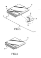
- FIG. 3 depicts a portion of inflatable seatbelt apparatus 10 in lap portion 24.
- inflatable seatbelt apparatus 10 comprises three layers, namely the inner airbag 34, the reinforcing sleeve 38 and the outer seatbelt 12.
- seatbelt 12 has substantial axial strength, it is designed to fail circumferentially under the pressure of airbag 34 when it inflates.
- seatbelt 12 may be provided with a longitudinal seam 42 at one or both edges, or seatbelt 12 may be scored, stitched, creased or otherwise provided with a weakened area running along the length of seatbelt 12 in the area surrounding airbag 34.
- the weakened area is referred to as a seam irrespective of whether it is a true seam or some other feature provided area functions as a locally weakened area.
- Reinforcing sleeve 38 has sufficient circumferential strength to resist rupturing under the pressure of airbag 34 as it inflates.
- inflatable seatbelt apparatus 10 comprises only two layers, namely the inner airbag 34 and the outer seatbelt 12. Therefore, in the torso portion 26, the airbag 34 is able to rupture outer seatbelt 12.
- reinforcing sleeve 38 expands into a cylindrical shape but does not rupture to permit airbag 34 to fully inflate.
- reinforcing sleeve 38 is absent and therefore as airbag 34 inflates seatbelt 12 ruptures along an axial seam allowing airbag 34 to inflate to its full diameter.
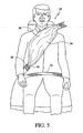
- inflator 28 when the vehicle collides with an obstacle or other obstacles at higher intensity than a predetermined value, inflator 28 is activated to begin a flow of inflation gases into airbag 34.
- reinforcing sleeve 38 prevents airbag 34 from inflating beyond the diameter of reinforcing sleeve 38. This prevents lap portion 24 from expanding to form a large diameter bag that would tend to roll up the hips of the occupant causing the occupant to submarine under the belt.
- reinforcing sleeve 38 comprises a 500 x 1000 denier polyester fabric tube with the 1000 denier fibers running in the circumferential direction. Accordingly, reinforcing sleeve 38 does not tear under the inflation pressure of airbag 34.
- reinforcing sleeve 38 is made from a somewhat lighter material, for example a 500 x 500 denier polyester. Since the fabric is relatively notch sensitive, although it will not rupture under the inflation pressure of airbag 34, it can be designed so that a tear will propagate if a stress concentration is provided. To this end, as shown in FIG.
- a notch 44 is cut transverse to open end 46 of reinforcing sleeve 48.
- the notch 44 in combination with the lighter circumferential denier of reinforcing sleeve 48, permits a tear in reinforcing sleeve 48 to propagate from open end 46 toward tongue fitting 18 as airbag 34 is deployed. As with the embodiment of FIGs. 1-5 , this enables the airbag to fully innate across torso portion 26 irrespective of the size of the occupant.
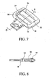
- tongue fitting 18 includes an eyelet 16 through which seatbelt 12 passes to enable seatbelt 12 automatically adjust to fit vehicle occupants of different sizes.
- Eyelet 16 comprises a slot formed between a body 50 of tongue fitting 18 and a flange 52 that is attached to body 50.
- the slot 54 that forms eyelet 16 is sized to permit seatbelt 12 to pass therethrough but is sufficiently narrow to prevent seatbelt 12 from twisting or rolling as it passes through eyelet 16. Because slot 54 is narrow, if left intact, slot 54 would restrict the flow of air from lap portion 24 into torso portion 26. Accordingly, as shown in FIG.
- flange 52 may be snapped in place or otherwise releasably mounted to tongue fitting 18 so that as to airbag 34 inflates flange 52 is dislodged from slot 54.
- flange 52 may be constructed of frangible plastic material, such as polystyrene, overmolded onto tongue fitting 18 and provided with an undercut section 56 which will allow flange 52 to fracture and be dislodged from slot 54 as airbag 34 inflates.
- conventional seatbelt airbags are ordinarily stitched within seatbelt 12 by means of a conventional "Box-X" stitch 58.
- a Box-X stitch is relatively inflexible and causes seatbelt 12 to interfere with the belt retractor 30.
- the sudden transition from the portion of a seatbelt containing an airbag and the portion of the seatbelt not containing the airbag causes a step in the seatbelt material that also interferes with the retractor.
- end 60 of airbag 34 that is distal from fixed end 36 is cut into a taper.
- the taper is effected by cutting the airbag 34 into a series of steps 62 that correspond with each of the pleats 64 of airbag 34.
- the pitch of the steps 62 are 1 ⁇ 2 inch each for a total tapered section 2 inches in length.
- a series of arc stitches 66 form the closure for airbag 34.
- a zigzag stitch 66 having three points and extending approximately 2 inches along the length of seatbelt 12 secures airbag 34 to seatbelt 12.
- a plurality of linear stitches 68 run the length of seatbelt 12 distal of end 60 of airbag 34 to maintain seatbelt 12 in its flattened condition to facilitate winding and unwinding from retractor 30.
- the combination of steps 62 and zigzag stitch 66 cooperate to provide a smooth transition from distal portion 70 of seatbelt 12 where no airbag is present to the proximal portion 72 of seatbelt 12 containing airbag 34.
Landscapes
- Engineering & Computer Science (AREA)
- Mechanical Engineering (AREA)
- Air Bags (AREA)
- Woven Fabrics (AREA)
Description
- This invention relates generally to automotive safety devices and in particular to seatbelt safety devices for protecting vehicle occupants.
- Seatbelt devices used to secure vehicular occupants in their seats typically comprise a single continuous length of webbed belt, one end of which is rigidly attached to the vehicle frame and the other end attached to an automatic retractor also mounted to the vehicle frame. The belt passes through a slot formed in a metal tongue that is plugged into a latch mounted to the floor of the vehicle on the side of the seat opposite the retractor and the rigid mount. The rigid mount, latch and retractor thus form a 3-point restraint.
- It is generally preferable to mount the automatic retractor so that the seatbelt webbing is paid out over the shoulder of the occupant so that the occupant is freely able to lean forward and backward without the necessity of paying the seatbelt webbing in and out across the occupant's lap and through the slot in the latch tongue as would be necessary with a floor mounted retractor. Consequently, the most popular front seat passenger restraint systems comprise a rigid mount at the floor and a retractor mounted proximal to the floor in the area of the B-pillar of the vehicle. The retractor pays out and retracts the seatbelt webbing typically through a D-ring attached to the B-pillar above the area of the occupant's shoulder.
- Conventional seatbelt webbing measures approximately 2 inches across its width. This two inch dimension is, however, a compromise between comfort and function. It has long been recognized that because of this limited width, the seatbelt webbing places enormous local loads on the passenger when restraining the passenger in a collision. Yet, ordinary webbing cannot be made substantially wider without rendering the seatbelt too cumbersome to use. In efforts to solve this problem, inflatable seatbelt apparatus have been proposed.
-
U.S. Patent No. 3,841,654 to Lewis discloses a vehicle safety system in which a seatbelt has an inflatable section that is normally maintained in an uninflated state. The seat belt is positioned about a wearer when the wearer is seated in a seat within the vehicle. Inflating means are provided that are capable of inflating the inflatable section prior to any substantial forward motion of the seatbelt wearer relative to the seatbelt. By providing an inflatable belt, the load of the occupant against the seatbelt is distributed over a much wider area and, therefore, the occupant is much less likely to be injured by the seatbelt. - Because of the industry preference for seatbelt retractors that pay out and retract the seatbelt over the occupant's shoulder, the most practical location to mount the inflator for an inflatable seatbelt is near the fixed end of the belt which is attached directly to the vehicle frame near the floor. This substantially simplifies the design of any electrical interconnections or other connections between the inflator and the vehicle. Unfortunately, mounting of the inflator at the stationary end of the seatbelt webbing dictates that, during a collision, gas from the inflator must pass through the lap portion of the seatbelt and past the bend at the tongue in order to inflate the most critical part of the inflatable seatbelt, namely that portion of the seatbelt across the occupant's torso.
- United States Patent No.
5,383,713 to Kamiyama, et al. discloses an inflatable seatbelt apparatus comprising a floor mounted inflator coupled to a seatbelt airbag in which the eyelet in the tongue has a movable flap that opens to permit gas from the inflator to enter the torso portion of the seatbelt airbag. -
US5 383 713 also discloses all the features of a seat belt device according to the preamble of claim 1 and a seat belt airbag according to the preamble ofclaim 8 and therefore is considered to be representative of the closest prior art. -
US2002/0074783 A1 discloses an airbag belt with a three layer structure comprising an airbag inserted into a mesh webbing which is, in turn, enclosed by a tube-like mesh cover which is designed to rupture upon inflation of the airbag. - United States Patent No.
5,474,326 to Cho , discloses a seatbelt airbag having a tongue eyelet equipped with a breakaway flap that opens during inflation to allow gas to pass from the lap portion of the belt into the torso portion of the belt. Although Kamiyama and Cho provide for a larger aperture through the eyelet in the seatbelt tongue, neither provide a substantial solution to the problem of the fabric pinching around the tongue, which will inherently impede gas flow. United States Patent No.6,340,173 to Specht, discloses a seatbelt airbag in which the lap portion of the belt includes a non-collapsing internal tube in the lap portion of the belt. The tube directs the output from the inflator into the torso portion of the belt. The rigid internal tube, however, renders the lap portion of the seatbelt bulky and awkward to wear. - Accordingly, what is needed is an inflatable seatbelt apparatus that reliably inflates the torso portion of the inflatable seatbelt, yet remains flat and comfortable to wear when uninflated.
- The present invention comprises a seatbelt airbag in which a portion of the airbag is encased in a sleeve that prevents the airbag from fully inflating in the area surrounded by the sleeve.
- According to an illustrative embodiment, the seatbelt airbag comprises a flexible fabric tube, the first end of which is attached to the floor of the vehicle and the second end of which is wound over a conventional seatbelt retractor. In the uninflated condition, the fabric tube forms a flat belt that passes in a conventional manner through a slotted eyelet in a tongue member that is plugged into a conventional floor-mounted seatbelt buckle. The flexible fabric tube thus forms a conventional 3-point restraint having a lap portion and a torso portion. An inflatable airbag member is disposed within the flexible fabric tube extending from a position proximal the fixed end of the fabric tube and extending past the tongue fitting into the torso portion of the seatbelt. A seatbelt airbag inflator is in fluid communication with the inflatable airbag member near the fixed end of the seatbelt. The inflator can either be floor mounted with a tube leading into the airbag member or may be mounted within the seatbelt itself. The airbag member is encased for part of its length within a reinforcing sleeve. One end of the reinforcing sleeve is closed and is essentially coincident with the closed end of the inflatable airbag member at the inflator end. The length of the reinforcing sleeve is selected such that the open end of the reinforcing sleeve is just beyond the tongue fitting when the seatbelt is being used by a 95th percentile man.
- The flexible fabric tube comprising the seatbelt has a longitudinal seam, stress concentration or other weakness that is designed to fail to allow the tube to rupture under the inflation pressure of the inflatable airbag member. The reinforcing sleeve, however, is of sufficient strength to resist rupturing under the inflation pressure of the inflatable airbag member. Accordingly, in operation, when a vehicle equipped with an illustrative seatbelt airbag collides with an obstacle or other obstacles at higher intensity than a predetermined value, the inflatable air member is pressurized. In the area surrounded by the reinforcing sleeve, the inflatable airbag member expands to the size of the reinforcing sleeve to form a gas channel, but does not rupture the reinforcing sleeve or the surrounding seatbelt tube. The portion of the inflatable airbag that extends beyond the open end of the reinforcing tube, however, ruptures the seatbelt tube and expands to its full diameter. As the airbag expands, the enlarged area of the airbag presses against the open end of the reinforcing sleeve. This causes the reinforcing sleeve to buckle and collapse backward toward the tongue fitting in an accordion-like fold. Thus, the sleeve retracts toward the tongue fitting to permit the airbag to fully inflate across the torso of the occupant. Alternatively, the reinforcing sleeve is provided with a stress concentration at the open end. When the airbag inflates, a tear propagates from the stress concentration at the open end to the tongue fitting, thereby allowing the airbag to fully inflate across the torso of the occupant.
- The present invention will be better understood from a reading of the following detailed description, taken in conjunction with the accompanying drawing figures in which like references designate like elements and, in which:
-
FIG. 1 is a perspective view of a seatbelt incorporating features of the present invention; -
FIG. 2 is an exploded perspective view of a seatbelt incorporating features of the present invention; -
FIG. 3 is a cutaway view of the seatbelt ofFIG. 1 in the region of lines 33; -
FIG. 4 is a cutaway view of the seatbelt ofFIG. 1 in the region oflines 44; -
FIG. 5 is a view of the seatbelt ofFIG. 1 in the deployed condition; -
FIG. 6 is a plan view of an alternative embodiment of a reinforcing sleeve incorporating features of the present invention. -
FIG. 7 is a view of a seatbelt tongue for use with a seatbelt incorporating features of the present invention; -
FIG. 8 is a cross-sectional view of the seatbelt tongue ofFIG. 6 ; -
FIG. 9 is a plan view of a prior art "Box X" stitch for joining portions of seatbelt webbing together; -
FIG. 10 is a side view of an inflatable airbag for use in a seatbelt incorporating features of the presentation invention; and -
FIG. 11 is a plan view of a stitching pattern for securing the airbag within the seatbelt webbing in accordance with the present invention. - The drawing figures are intended to illustrate the general manner of construction and are not necessarily to scale. In the detailed description and in the drawing figures, specific illustrative examples are shown and herein described in detail. It should be understood, however, that the drawing the figures and detailed description are not intended to limit the invention to the particular form disclosed, but are merely illustrative and intended to teach one of ordinary skill how to make and/or use the invention claimed herein and for setting forth the best mode for carrying out the invention.
- With reference to
FIG. 1 ,inflatable seatbelt apparatus 10 comprises aseatbelt 12 formed of a continuous piece of tubular webbing that is flattened to form the belt.Seatbelt 12 is attached at one end to the vehicle frame, typically near the floor, by anend fitting 14. The opposite end ofseatbelt 12 is guided through aneyelet 16 in a tongue fitting 18, which forms the male portion of a conventional seatbelt buckle. From there,seatbelt 12 is routed to a belt retractor 30 (not shown inFIG. 1 ) in a manner well known in the art, for example through a D-ring 22, preferably a roller D-Ring, mounted to the B-pillar of the vehicle. Thus mounted,seatbelt 12 forms a conventional 3 point restraint for an occupant ofseat 20 comprising alap portion 24 and atorso portion 26. An inflator 28 is mounted withinseatbelt 12 to provide a source of inflation gas for inflating the inflatable portion ofseatbelt apparatus 10 in a manner described more fully hereinafter.Inflator 28 may be any conventional source of inflation gas, whether floor mounted with a tubular connection to the inflatable portion or mounted within the inflatable portion. In theillustrative embodiment inflator 28 comprises the high efficiency inflator disclosed inU.S. Patent No. 6,142,511 to Lewis . - With reference to
FIG. 2 , the principal components of the seatbelt ofFIG. 1 comprise the end fitting 14 to whichseatbelt 12 is attached proximal to the floor of the vehicle.Seatbelt 12 passes througheyelet 16 of tongue fitting 18 through D-ring 22 to aconventional retractor 30. Tongue fitting 18 is adapted to be received in abuckle 32 in a conventional manner. Disposed withinseatbelt 12 isairbag 34 which, in the illustrative embodiment comprises an elongate tubular bag composed of 210 x 2 10 denier silicone coated nylon fabric that is folded into five pleats along one edge in a so-called "rooster tail" fold pattern to form a relatively flat ribbon of material contained with inseatbelt 12.Inflator 28 is disposed withinairbag 34 proximalfixed end 36 ofseatbelt 12. A reinforcing sleeve is disposed aroundairbag 34 withinseatbelt 12. In the illustrative embodiment, reinforcingsleeve 38 comprises an elongate tube composed of 500 x 1000 denier polyester, with the 1000 denier fibers running in the circumferential direction.Seatbelt 12, reinforcingsleeve 38 andairbag 34 are stitched together proximal thefixed end 36 ofseatbelt 12 to form a relatively leak free end. The length of reinforcingsleeve 38 is selected such that theopen end 40 of reinforcingsleeve 38 extends justpast eyelet 16 of tongue fitting 18 whenseatbelt 12 is being worn by a 95th percentile male.Open end 40 ofsleeve 38, therefore, extends substantially intotorso portion 26 ofseatbelt 12 when being worn by a 5 percentile woman. Because the illustrative seatbelt airbag is self-adjusting as described more fully herein, it is inconsequential that the reinforcingsleeve 38 extends substantially intotorso portion 26 as long assleeve 38 extends at least to tongue fitting 18. - The construction of the
inflatable seatbelt apparatus 10 of the illustrative embodiment is described in further detail with reference toFIGs. 3 and 4. FIG. 3 depicts a portion ofinflatable seatbelt apparatus 10 inlap portion 24. Inlap portion 24,inflatable seatbelt apparatus 10 comprises three layers, namely theinner airbag 34, the reinforcingsleeve 38 and theouter seatbelt 12. Althoughseatbelt 12 has substantial axial strength, it is designed to fail circumferentially under the pressure ofairbag 34 when it inflates. To that end,seatbelt 12 may be provided with alongitudinal seam 42 at one or both edges, orseatbelt 12 may be scored, stitched, creased or otherwise provided with a weakened area running along the length ofseatbelt 12 in thearea surrounding airbag 34. (As used herein, the weakened area is referred to as a seam irrespective of whether it is a true seam or some other feature provided area functions as a locally weakened area.) Reinforcingsleeve 38, however, has sufficient circumferential strength to resist rupturing under the pressure ofairbag 34 as it inflates. - As shown in
FIG. 4 , intorso portion 26,inflatable seatbelt apparatus 10 comprises only two layers, namely theinner airbag 34 and theouter seatbelt 12. Therefore, in thetorso portion 26, theairbag 34 is able to ruptureouter seatbelt 12. Thus, asairbag 34 inflates, inlap portion 24 reinforcingsleeve 38 expands into a cylindrical shape but does not rupture to permitairbag 34 to fully inflate. In thetorso portion 26, however, reinforcingsleeve 38 is absent and therefore asairbag 34 inflatesseatbelt 12 ruptures along an axialseam allowing airbag 34 to inflate to its full diameter. - With reference to
FIG. 5 , in operation, when the vehicle collides with an obstacle or other obstacles at higher intensity than a predetermined value,inflator 28 is activated to begin a flow of inflation gases intoairbag 34. Inlap portion 24, reinforcingsleeve 38 preventsairbag 34 from inflating beyond the diameter of reinforcingsleeve 38. This preventslap portion 24 from expanding to form a large diameter bag that would tend to roll up the hips of the occupant causing the occupant to submarine under the belt. At the same time, allowingairbag 34 to expand to the diameter of reinforcingsleeve 38 causesairbag 34 to form a channel to direct the inflation gases intotorso portion 26 whereairbag 34, unconstrained by reinforcingsleeve 38, expands to its full diameter to provide a cushion foroccupant 42. Asairbag 34 expands, the expansion causesairbag 34 to press againstopen end 40 of reinforcingsleeve 38. This causes reinforcingsleeve 38 to buckle and collapse backward toward tongue fitting 18 in an accordion-like fold. This allows reinforcingsleeve 38 to retract toward tongue fitting 18 permittingairbag 34 to fully inflate acrosstorso portion 26 irrespective of the size of the occupant being restrained. - As noted hereinbefore, in the illustrative embodiment, reinforcing
sleeve 38 comprises a 500 x 1000 denier polyester fabric tube with the 1000 denier fibers running in the circumferential direction. Accordingly, reinforcingsleeve 38 does not tear under the inflation pressure ofairbag 34. In an alternative embodiment, as shown inFIG. 6 , reinforcingsleeve 38 is made from a somewhat lighter material, for example a 500 x 500 denier polyester. Since the fabric is relatively notch sensitive, although it will not rupture under the inflation pressure ofairbag 34, it can be designed so that a tear will propagate if a stress concentration is provided. To this end, as shown inFIG. 6 , anotch 44 is cut transverse to openend 46 of reinforcingsleeve 48. Thenotch 44 in combination with the lighter circumferential denier of reinforcingsleeve 48, permits a tear in reinforcingsleeve 48 to propagate fromopen end 46 toward tongue fitting 18 asairbag 34 is deployed. As with the embodiment ofFIGs. 1-5 , this enables the airbag to fully innate acrosstorso portion 26 irrespective of the size of the occupant. - As shown in
FIG. 7 , tongue fitting 18 includes aneyelet 16 through whichseatbelt 12 passes to enableseatbelt 12 automatically adjust to fit vehicle occupants of different sizes.Eyelet 16 comprises a slot formed between abody 50 of tongue fitting 18 and aflange 52 that is attached tobody 50. Theslot 54 that forms eyelet 16 is sized to permitseatbelt 12 to pass therethrough but is sufficiently narrow to preventseatbelt 12 from twisting or rolling as it passes througheyelet 16. Becauseslot 54 is narrow, if left intact,slot 54 would restrict the flow of air fromlap portion 24 intotorso portion 26. Accordingly, as shown inFIG. 8 ,flange 52 may be snapped in place or otherwise releasably mounted to tongue fitting 18 so that as toairbag 34 inflatesflange 52 is dislodged fromslot 54. Alternatively,flange 52 may be constructed of frangible plastic material, such as polystyrene, overmolded onto tongue fitting 18 and provided with an undercutsection 56 which will allowflange 52 to fracture and be dislodged fromslot 54 asairbag 34 inflates. - With reference to
FIG. 9 , conventional seatbelt airbags are ordinarily stitched withinseatbelt 12 by means of a conventional "Box-X"stitch 58. Unfortunately, a Box-X stitch is relatively inflexible and causesseatbelt 12 to interfere with thebelt retractor 30. Similarly, the sudden transition from the portion of a seatbelt containing an airbag and the portion of the seatbelt not containing the airbag causes a step in the seatbelt material that also interferes with the retractor. Accordingly, as shown inFIGs. 10 and 11 , in the illustrative embodiment, end 60 ofairbag 34 that is distal from fixedend 36 is cut into a taper. In the illustrative embodiment, the taper is effected by cutting theairbag 34 into a series ofsteps 62 that correspond with each of thepleats 64 ofairbag 34. In the illustrative embodiment, the pitch of thesteps 62 are ½ inch each for a total tapered section 2 inches in length. A series of arc stitches 66 form the closure forairbag 34. Azigzag stitch 66 having three points and extending approximately 2 inches along the length ofseatbelt 12 securesairbag 34 toseatbelt 12. A plurality oflinear stitches 68 run the length ofseatbelt 12 distal ofend 60 ofairbag 34 to maintainseatbelt 12 in its flattened condition to facilitate winding and unwinding fromretractor 30. The combination ofsteps 62 andzigzag stitch 66 cooperate to provide a smooth transition fromdistal portion 70 ofseatbelt 12 where no airbag is present to theproximal portion 72 ofseatbelt 12 containingairbag 34. - Although certain illustrative embodiments and methods have been disclosed herein, it will be apparent from the foregoing disclosure to those skilled in the art that variations and modifications of such embodiments and methods may be made without other inflators departing from the scope of the invention. Accordingly, it is intended that the invention shall be limited only to the extent required by the appended claims and the rules and principals of applicable law.
Claims (12)
- A seat belt device (10) for protecting the occupant of a vehicle comprising:a tongue fitting (18) having an eyelet formed therein, said tongue fitting (18) adapted to be received by a seat belt buckle (32) attached to said vehicle;a seat belt retractor (30) attached to said vehicle;a seat belt (12) comprising a flexible fabric tube having a first fixed end (36) attached to said vehicle, a second end attached to said seat belt retractor (30), and a medial portion passing through said eyelet formed in said tongue fitting (18), said seat belt (12) forming a three point restraint including a lap portion (24) extending from said fixed end (36) to said tongue fitting (18) and a torso portion (26) extending from said tongue fitting (18) toward said seat belt retractor (30);an inflatable air bag member (34) disposed within said seat belt (12), said inflatable air bag member (34) extending within said seat belt (12) from a first end proximal said fixed end (36) of said seat belt (12) to a second end within said torso portion (26) of said seat belt (12); andan inflator (28) fluidly connected with said inflatable air bag member (34) for providing a source of pressurized gas for inflating said inflatable air bag member (34);characterized in thatsaid seat belt (12) further comprises a reinforcing sleeve (38), said reinforcing sleeve (38) comprising a flexible fabric sleeve having a closed end and an open end (40), said reinforcing sleeve (38) forming an annular layer between said inflatable air bag member (34) and said flexible fabric tube, said reinforcing sleeve (38) extending from said closed end proximal said first end of said inflatable air bag member (34) to said open end (40) within said torso portion (26) of said seat belt (12) just past eyelet (16) of tongue fitting (18) when seat belt (12) is being worn by a 95th percentile male.
- The seat belt device of claim 1, wherein:said flexible fabric tube includes a longitudinal seam (42) adapted to rupture as said inflatable air bag member (34) inflates.
- The seat belt device of claim 1, wherein:said reinforcing sleeve (38) comprises a stress concentration at said open end (40), said stress concentration being capable of initiating a tear in said reinforcing sleeve (38) that propagates toward said eyelet as said inflatable air bag member (34) is inflated.
- The seat belt device of claim 3, wherein:said stress concentration comprises a notch cut into said reinforcing sleeve (38) intersecting said open end (40) of said reinforcing sleeve (38).
- The seat belt device of claim 1, wherein:said reinforcing sleeve comprises a fabric having a denier of no greater than 1000 x 1000.
- The seat belt device of claim 1, wherein:said reinforcing sleeve comprises a fabric having a denier of no greater than 500.
- The seat belt device of claim 1, wherein:said inflatable air bag member (34) comprises a fabric tube that, in an uninflated condition assumes the shape of a flat belt having a first and a second lateral edge, said fabric tube being folded into a rooster-tail fold comprising a plurality of pleats along said first lateral edge and a single apex along said second lateral edge.
- A seat belt airbag comprising:an inner layer consisting of an inflatable air bag member (34), said inflatable air bag member (34) comprising an elongate tubular mem ber that, in an un-inflated condition assumes the shape of a flat belt having a first and a second lateral edge and a first and a second end, said elongate tubular member being folded and adapted to deploy under an inflation pressure;an outer layer (12) comprising a flexible fabric tube surrounding said inflatable air bag member (34), said outer layer (12) having a longitudinal weakened seam (42) such that said outer layer (12) is incapable of containing said inflatable air bag member (34) under said inflation pressure;characterized in thatthe seat belt airbag further comprises a middle layer arranged between said inner layer and said outer layer (12), said middle layer comprising a reinforcing sleeve (38) surrounding said inflatable air bag member (34) and extending from said first end of said inflatable air bag member (34) to a point medial of said first and second ends of said inflatable air bag member (34), said middle layer comprising a flexible fabric tube having sufficient strength to contain said inflateable air bag member (34) under said inflation pressure; whereinsaid elongate tubular member of said inflatable air bag member (34) is folded into a rooster-tail fold comprising a plurality of pleats along said first lateral edge and a single apex along said second lateral edge.
- The seat belt airbag of claim 8, wherein:said reinforcing sleeve (38) comprises a stress concentration at said open end (40), said stress concentration being capable of initiating a tear in said reinforcing sleeve (38) that propagates toward said eyelet as said inflatable air bag member (34) is inflated.
- The seat belt airbag of claim 9, wherein:said stress concentration comprises a notch cut into said reinforcing sleeve (38) intersecting said open end of said reinforcing sleeve.
- The seat belt airbag of claim 8, wherein:said reinforcing sleeve (38) comprises a fabric having a denier of no greater than 1000 x 1000.
- The seat belt airbag of claim 8, wherein:said reinforcing sleeve (38) comprises a fabric having a denier of no greater than 500.
Applications Claiming Priority (4)
| Application Number | Priority Date | Filing Date | Title |
|---|---|---|---|
| US613440 | 1990-11-15 | ||
| US44966003P | 2003-02-24 | 2003-02-24 | |
| US449660P | 2003-02-24 | ||
| US10/613,440 US6951350B2 (en) | 2003-02-24 | 2003-07-02 | Seatbelt airbag |
Publications (2)
| Publication Number | Publication Date |
|---|---|
| EP1457392A1 EP1457392A1 (en) | 2004-09-15 |
| EP1457392B1 true EP1457392B1 (en) | 2013-10-16 |
Family
ID=32776289
Family Applications (1)
| Application Number | Title | Priority Date | Filing Date |
|---|---|---|---|
| EP04004143.6A Expired - Lifetime EP1457392B1 (en) | 2003-02-24 | 2004-02-24 | Seatbelt Airbag |
Country Status (3)
| Country | Link |
|---|---|
| US (1) | US6951350B2 (en) |
| EP (1) | EP1457392B1 (en) |
| JP (1) | JP2004256099A (en) |
Families Citing this family (43)
| Publication number | Priority date | Publication date | Assignee | Title |
|---|---|---|---|---|
| JP4734933B2 (en) * | 2004-02-27 | 2011-07-27 | タカタ株式会社 | Vehicle occupant protection system and inflator |
| US7639927B2 (en) | 2004-09-14 | 2009-12-29 | Marvell World Trade Ltd. | Unified control and memory for a combined DVD/HDD system |
| US7472925B2 (en) * | 2004-10-12 | 2009-01-06 | Van Freeman Industries Llc | Ergonomic seatbelt for improved belt safety and comfort |
| DE102005016211B4 (en) * | 2005-04-07 | 2007-05-10 | Autoliv Development Ab | Fastening arrangement for a safety belt |
| US7263750B2 (en) | 2005-06-09 | 2007-09-04 | Amsafe, Inc. | Buckle assembly having single release for multiple belt connectors |
| DE102005049893B4 (en) * | 2005-10-17 | 2014-09-04 | Autoliv Development Ab | Locking tongue and security system with a tongue |
| JP4923529B2 (en) * | 2005-11-14 | 2012-04-25 | タカタ株式会社 | Crew restraint system |
| US20090224595A1 (en) * | 2008-03-10 | 2009-09-10 | Pfefferman Craig A | Seat belt extension device |
| US7980590B2 (en) | 2008-03-19 | 2011-07-19 | Amsafe, Inc. | Inflatable personal restraint systems having web-mounted inflators and associated methods of use and manufacture |
| US7665761B1 (en) | 2008-03-27 | 2010-02-23 | Amsafe, Inc. | Inflatable personal restraint systems and associated methods of use and manufacture |
| US8469401B2 (en) | 2009-02-23 | 2013-06-25 | Amsafe, Inc. | Seat harness pretensioner |
| US8683666B2 (en) | 2009-11-04 | 2014-04-01 | Amsafe Commercial Products, Inc. | Restraint system buckle components having tactile surfaces, and associated methods of use and manufacture |
| US8627554B1 (en) | 2010-05-03 | 2014-01-14 | Amsafe, Inc. (Phoenix Group) | Buckle assemblies with swivel and dual release features and associated methods of use and manufacture |
| DE102010023478B4 (en) | 2010-06-11 | 2023-11-09 | Mercedes-Benz Group AG | Seat belt for a vehicle |
| DE102010026546B4 (en) * | 2010-07-08 | 2021-10-21 | Daimler Ag | Seat belt for a vehicle |
| US8777323B2 (en) | 2010-07-20 | 2014-07-15 | Amsafe, Inc. | Restraint harnesses and associated methods of use and manufacture |
| US9409537B2 (en) * | 2010-09-20 | 2016-08-09 | Trw Vehicle Safety Systems, Inc. | Seat belt system |
| US8882141B2 (en) * | 2010-10-28 | 2014-11-11 | Key Safety Systems, Inc. | Single retractor inflatable belt system |
| DE102010053311A1 (en) * | 2010-12-02 | 2012-06-06 | Daimler Ag | Belt for a safety belt of a vehicle |
| US8469397B2 (en) | 2011-04-13 | 2013-06-25 | Amsafe, Inc. | Stitch patterns for restraint-mounted airbags and associated systems and methods |
| USD688156S1 (en) | 2011-05-16 | 2013-08-20 | Amsafe, Inc. | Connector for a seatbelt airbag |
| US8556293B2 (en) | 2011-05-16 | 2013-10-15 | Amsafe, Inc. | Buckle connectors for inflatable personal restraints and associated methods of use and manufacture |
| US8439398B2 (en) | 2011-07-29 | 2013-05-14 | Amsafe, Inc. | Inflator connectors for inflatable personal restraints and associated systems and methods |
| US9511866B2 (en) | 2012-03-19 | 2016-12-06 | Amsafe, Inc. | Structure mounted airbag assemblies and associated systems and methods |
| US8523220B1 (en) | 2012-03-19 | 2013-09-03 | Amsafe, Inc. | Structure mounted airbag assemblies and associated systems and methods |
| US9022483B2 (en) | 2012-06-07 | 2015-05-05 | Shield Restraint Systems, Inc. | Seatbelt buckle tongue assembly |
| US9616747B1 (en) | 2013-01-29 | 2017-04-11 | Intelligent Technologies International, Inc. | Method for controlling travel of golf carts and all-terrain vehicles |
| EP2958453A4 (en) | 2013-02-19 | 2016-07-27 | Amsafe Inc | Buckle assemblies with lift latches and associated methods and systems |
| US9277788B2 (en) | 2013-02-19 | 2016-03-08 | Amsafe, Inc. | Dual release buckle assemblies and associated systems and methods |
| JP5850008B2 (en) * | 2013-08-21 | 2016-02-03 | トヨタ自動車株式会社 | Air belt device |
| US20160244173A1 (en) * | 2014-03-18 | 2016-08-25 | Takata Protection Systems, Inc. | Three point air belt |
| JP6200856B2 (en) * | 2014-06-03 | 2017-09-20 | 株式会社東海理化電機製作所 | Webbing device |
| US9393926B2 (en) * | 2014-08-27 | 2016-07-19 | Autoliv Asp, Inc. | Folding patterns of an inflatable seat belt |
| US9352839B2 (en) | 2014-10-02 | 2016-05-31 | Amsafe, Inc. | Active positioning airbag assembly and associated systems and methods |
| DE102014222654B4 (en) * | 2014-11-06 | 2022-08-25 | Autoliv Development Ab | Webbing for a seat belt device and seat belt device |
| US9775410B2 (en) | 2014-12-16 | 2017-10-03 | Shield Restraint Systems, Inc. | Web adjusters for use with restraint systems and associated methods of use and manufacture |
| US9944245B2 (en) | 2015-03-28 | 2018-04-17 | Amsafe, Inc. | Extending pass-through airbag occupant restraint systems, and associated systems and methods |
| SG11201708221UA (en) | 2015-04-11 | 2017-11-29 | Amsafe Inc | Active airbag vent system |
| DE102015207649A1 (en) | 2015-04-27 | 2016-10-27 | Bayerische Motoren Werke Aktiengesellschaft | Safety and comfort restraint device for a vehicle occupant and method for operating this device |
| US10604259B2 (en) | 2016-01-20 | 2020-03-31 | Amsafe, Inc. | Occupant restraint systems having extending restraints, and associated systems and methods |
| US9814282B2 (en) | 2016-02-02 | 2017-11-14 | Shield Restraint Systems, Inc. | Harsh environment buckle assemblies and associated systems and methods |
| US10611334B2 (en) | 2017-02-07 | 2020-04-07 | Shield Restraint Systems, Inc. | Web adjuster |
| US11110879B2 (en) * | 2019-11-11 | 2021-09-07 | Ford Global Technologies, Llc | Airbag inflatable along a seatbelt webbing |
Family Cites Families (19)
| Publication number | Priority date | Publication date | Assignee | Title |
|---|---|---|---|---|
| US3841654A (en) | 1972-09-21 | 1974-10-15 | Allied Chem | Vehicle safety system |
| JP3057114B2 (en) * | 1991-10-21 | 2000-06-26 | タカタ株式会社 | Inflatable seat belt device |
| JP3057115B2 (en) * | 1991-10-21 | 2000-06-26 | タカタ株式会社 | Inflatable seat belt device |
| JP3110881B2 (en) * | 1992-08-06 | 2000-11-20 | タカタ株式会社 | Inflatable seat belt device |
| JP3110882B2 (en) * | 1992-08-06 | 2000-11-20 | タカタ株式会社 | Inflatable seat belt device |
| JP3278075B2 (en) * | 1992-08-06 | 2002-04-30 | タカタ株式会社 | Inflatable seat belt device |
| JP3113081B2 (en) * | 1992-08-18 | 2000-11-27 | タカタ株式会社 | Inflatable seat belt device |
| KR960008806B1 (en) * | 1994-01-28 | 1996-07-05 | 조성호 | Car air safety belt |
| US5465999A (en) * | 1994-06-30 | 1995-11-14 | Takata Corporation | Inflatable seat belt having defined shape |
| US6142511A (en) * | 1995-12-22 | 2000-11-07 | Universal Propulsion Company | Inflatable passenger restraint and inflator therefor |
| US5765869A (en) * | 1996-09-06 | 1998-06-16 | Huber; John F. | Automatically tightened seatbelt |
| US6126194A (en) * | 1997-03-31 | 2000-10-03 | Simula, Inc. | Inflatable tubular torso restraint system |
| DE19804365C2 (en) * | 1998-02-04 | 2000-06-08 | Hs Tech & Design | Three-point seat belt |
| JP3760632B2 (en) * | 1998-06-09 | 2006-03-29 | タカタ株式会社 | Air belt and air belt device |
| EP1087878B1 (en) | 1998-06-18 | 2004-08-25 | Universal Propulsion Company, Inc. | Belt system with inflatable section within an outer belt section and method of restraint |
| JP3945100B2 (en) * | 1999-11-05 | 2007-07-18 | タカタ株式会社 | Air belt and air belt device |
| JP4674832B2 (en) * | 2000-12-14 | 2011-04-20 | タカタ株式会社 | Air belt in inflatable seat belt device and inflatable seat belt device using this air belt |
| JP4573285B2 (en) * | 2000-12-18 | 2010-11-04 | タカタ株式会社 | Inflatable seat belt device |
| US6626456B2 (en) * | 2001-06-26 | 2003-09-30 | Autoliv Asp, Inc. | Apparatus and method for inflatable curtain wrap |
-
2003
- 2003-07-02 US US10/613,440 patent/US6951350B2/en not_active Expired - Lifetime
-
2004
- 2004-02-24 EP EP04004143.6A patent/EP1457392B1/en not_active Expired - Lifetime
- 2004-02-24 JP JP2004048479A patent/JP2004256099A/en active Pending
Also Published As
| Publication number | Publication date |
|---|---|
| US20040164532A1 (en) | 2004-08-26 |
| US6951350B2 (en) | 2005-10-04 |
| JP2004256099A (en) | 2004-09-16 |
| EP1457392A1 (en) | 2004-09-15 |
Similar Documents
| Publication | Publication Date | Title |
|---|---|---|
| US6951350B2 (en) | Seatbelt airbag | |
| US5865465A (en) | Air-bag | |
| US6340173B1 (en) | Three-point seat belt | |
| US7195276B2 (en) | Occupant protection system | |
| EP2265469B1 (en) | Inflatable personal restraint systems having web-mounted inflators and associated methods of use and manufacture | |
| US7322603B2 (en) | Seat belt system including an airbag | |
| EP3075610A1 (en) | Extending pass-through airbag occupant restraint systems, and associated systems and methods | |
| CN106604849B (en) | Folding mode of the inflatable seat belt | |
| CN114126930B (en) | Occupant restraint device | |
| US6688642B2 (en) | Concentrically disposed airbag system for seatbelts | |
| US6648369B2 (en) | Inflatable seat belt apparatus | |
| US7604253B2 (en) | Air belt apparatus | |
| US6698790B2 (en) | Air belt for inflatable seat belt device | |
| JP5446657B2 (en) | Air belt and air belt device | |
| EP1738971B1 (en) | Occupant restraint apparatus | |
| EP1783012A1 (en) | A Restraint System for a Vehicle | |
| EP0963883B1 (en) | Inflatable safety belt for motor vehicles | |
| JP3919820B2 (en) | Inflatable tubular torso restraint system | |
| WO2016194506A1 (en) | Air belt device | |
| JP3767173B2 (en) | Air belt bag | |
| US7398995B2 (en) | Air belt | |
| EP1950102B1 (en) | Air belt device | |
| CN215971413U (en) | Seat and vehicle | |
| JP2008100649A (en) | Occupant restraint system | |
| GB2405840A (en) | Seat-belt airbag |
Legal Events
| Date | Code | Title | Description |
|---|---|---|---|
| PUAI | Public reference made under article 153(3) epc to a published international application that has entered the european phase |
Free format text: ORIGINAL CODE: 0009012 |
|
| AK | Designated contracting states |
Kind code of ref document: A1 Designated state(s): AT BE BG CH CY CZ DE DK EE ES FI FR GB GR HU IE IT LI LU MC NL PT RO SE SI SK TR |
|
| AX | Request for extension of the european patent |
Extension state: AL LT LV MK |
|
| 17P | Request for examination filed |
Effective date: 20050315 |
|
| AKX | Designation fees paid |
Designated state(s): DE FR GB |
|
| RAP1 | Party data changed (applicant data changed or rights of an application transferred) |
Owner name: GOODRICH CORPORATION |
|
| 17Q | First examination report despatched |
Effective date: 20091217 |
|
| GRAP | Despatch of communication of intention to grant a patent |
Free format text: ORIGINAL CODE: EPIDOSNIGR1 |
|
| INTG | Intention to grant announced |
Effective date: 20130325 |
|
| GRAS | Grant fee paid |
Free format text: ORIGINAL CODE: EPIDOSNIGR3 |
|
| GRAP | Despatch of communication of intention to grant a patent |
Free format text: ORIGINAL CODE: EPIDOSNIGR1 |
|
| GRAA | (expected) grant |
Free format text: ORIGINAL CODE: 0009210 |
|
| INTG | Intention to grant announced |
Effective date: 20130910 |
|
| AK | Designated contracting states |
Kind code of ref document: B1 Designated state(s): DE FR GB |
|
| REG | Reference to a national code |
Ref country code: GB Ref legal event code: FG4D |
|
| REG | Reference to a national code |
Ref country code: DE Ref legal event code: R096 Ref document number: 602004043567 Country of ref document: DE Effective date: 20131212 |
|
| REG | Reference to a national code |
Ref country code: GB Ref legal event code: 732E Free format text: REGISTERED BETWEEN 20140619 AND 20140625 |
|
| REG | Reference to a national code |
Ref country code: DE Ref legal event code: R097 Ref document number: 602004043567 Country of ref document: DE |
|
| PLBE | No opposition filed within time limit |
Free format text: ORIGINAL CODE: 0009261 |
|
| REG | Reference to a national code |
Ref country code: FR Ref legal event code: TP Owner name: FORD GLOBAL TECHNOLOGIES, LLC, US Effective date: 20140704 |
|
| STAA | Information on the status of an ep patent application or granted ep patent |
Free format text: STATUS: NO OPPOSITION FILED WITHIN TIME LIMIT |
|
| 26N | No opposition filed |
Effective date: 20140717 |
|
| REG | Reference to a national code |
Ref country code: DE Ref legal event code: R082 Ref document number: 602004043567 Country of ref document: DE Representative=s name: GRAF GLUECK KRITZENBERGER, DE |
|
| REG | Reference to a national code |
Ref country code: DE Ref legal event code: R097 Ref document number: 602004043567 Country of ref document: DE Effective date: 20140717 |
|
| REG | Reference to a national code |
Ref country code: DE Ref legal event code: R081 Ref document number: 602004043567 Country of ref document: DE Owner name: FORD GLOBAL TECHNOLOGIES, LLC (N.D.GES.D. STAA, US Free format text: FORMER OWNER: UNIVERSAL PROPULSION CO., INC., CHARLOTTE, N.C., US Effective date: 20131018 Ref country code: DE Ref legal event code: R082 Ref document number: 602004043567 Country of ref document: DE Representative=s name: GRAF GLUECK KRITZENBERGER, DE Effective date: 20141010 Ref country code: DE Ref legal event code: R081 Ref document number: 602004043567 Country of ref document: DE Owner name: FORD GLOBAL TECHNOLOGIES, LLC (N.D.GES.D. STAA, US Free format text: FORMER OWNER: GOODRICH CORP., CHARLOTTE, N.C., US Effective date: 20141010 Ref country code: DE Ref legal event code: R082 Ref document number: 602004043567 Country of ref document: DE Representative=s name: GLUECK - KRITZENBERGER PATENTANWAELTE PARTGMBB, DE Effective date: 20141010 |
|
| REG | Reference to a national code |
Ref country code: FR Ref legal event code: PLFP Year of fee payment: 13 |
|
| REG | Reference to a national code |
Ref country code: FR Ref legal event code: PLFP Year of fee payment: 14 |
|
| REG | Reference to a national code |
Ref country code: FR Ref legal event code: PLFP Year of fee payment: 15 |
|
| PGFP | Annual fee paid to national office [announced via postgrant information from national office to epo] |
Ref country code: IT Payment date: 20190221 Year of fee payment: 9 Ref country code: GB Payment date: 20190128 Year of fee payment: 16 |
|
| GBPC | Gb: european patent ceased through non-payment of renewal fee |
Effective date: 20200224 |
|
| PG25 | Lapsed in a contracting state [announced via postgrant information from national office to epo] |
Ref country code: GB Free format text: LAPSE BECAUSE OF NON-PAYMENT OF DUE FEES Effective date: 20200224 Ref country code: FR Free format text: LAPSE BECAUSE OF NON-PAYMENT OF DUE FEES Effective date: 20200229 |
|
| PGFP | Annual fee paid to national office [announced via postgrant information from national office to epo] |
Ref country code: DE Payment date: 20230111 Year of fee payment: 20 |
|
| P01 | Opt-out of the competence of the unified patent court (upc) registered |
Effective date: 20230620 |
|
| REG | Reference to a national code |
Ref country code: DE Ref legal event code: R071 Ref document number: 602004043567 Country of ref document: DE |