EP1457389A1 - A battery arrangement - Google Patents
A battery arrangement Download PDFInfo
- Publication number
- EP1457389A1 EP1457389A1 EP03005380A EP03005380A EP1457389A1 EP 1457389 A1 EP1457389 A1 EP 1457389A1 EP 03005380 A EP03005380 A EP 03005380A EP 03005380 A EP03005380 A EP 03005380A EP 1457389 A1 EP1457389 A1 EP 1457389A1
- Authority
- EP
- European Patent Office
- Prior art keywords
- battery
- vehicle
- cable
- arrangement
- pole
- Prior art date
- Legal status (The legal status is an assumption and is not a legal conclusion. Google has not performed a legal analysis and makes no representation as to the accuracy of the status listed.)
- Granted
Links
Images
Classifications
-
- B—PERFORMING OPERATIONS; TRANSPORTING
- B60—VEHICLES IN GENERAL
- B60R—VEHICLES, VEHICLE FITTINGS, OR VEHICLE PARTS, NOT OTHERWISE PROVIDED FOR
- B60R16/00—Electric or fluid circuits specially adapted for vehicles and not otherwise provided for; Arrangement of elements of electric or fluid circuits specially adapted for vehicles and not otherwise provided for
- B60R16/02—Electric or fluid circuits specially adapted for vehicles and not otherwise provided for; Arrangement of elements of electric or fluid circuits specially adapted for vehicles and not otherwise provided for electric constitutive elements
- B60R16/03—Electric or fluid circuits specially adapted for vehicles and not otherwise provided for; Arrangement of elements of electric or fluid circuits specially adapted for vehicles and not otherwise provided for electric constitutive elements for supply of electrical power to vehicle subsystems or for
Definitions
- the present invention relates to an arrangement for reducing electromagnetic fields in a vehicle being arranged with a battery mounted in a first end of said vehicle, the arrangement comprising a first battery cable leading from the second end of said vehicle to a first pole of said battery, and a second pole of said battery being arranged with a second battery cable coupled to ground.
- the invention also relates to a vehicle comprising such an arrangement.
- electromagnetic fields For a number of reasons, it is desirable to limit such fields.
- the electromagnetic fields of most interest in this are "low-frequency" electromagnetic fields, that is those having a frequency range of about 25 to 1000 Hz.
- a known solution to help reduce electromagnetic fields is to lead the return current through a new cable back to the engine area where it is coupled to ground, instead of leading the return current through the car body. Since the battery cable and the new cable both lead approximately the same current but in the opposite directions, the resulting electromagnetic field will be nearly zero.
- this design implies that the cable for the return current must have the same dimensions as the existing battery cable, which is generally quite thick. Furthermore, this solution increases the resistance of the circuit which comprises the battery and the engine cranking motor, leading to start problems of the vehicle at low outside temperatures.
- the charge current flowing toward the battery in the first battery cable comprises d.c. (direct current) and a.c. (alternating current) parts, and the return current of the battery comprises d.c. and a.c. parts as well.
- said second battery cable is coupled to ground via a low-pass filter. More preferably, the low-pass filter is constituted of an inductor.
- the low-pass filter divides the return current of the battery into d.c. parts and a.c. parts, whereof the d.c. parts flow in the body from the battery to an opposite part of the vehicle, and the a.c. parts flow in the additional cable to the opposite part of the vehicle.
- the opposite part of the vehicle can be a first end of the vehicle, e.g. the rear.
- the opposite part of the vehicle can also be a second end, e.g. the front.
- the inventive arrangement is used when the engine is arranged in the front of the vehicle and the battery is arranged in the rear of the vehicle.
- the arrangement of the present invention can also be used when the engine is arranged in the rear of the vehicle and the battery is arranged in the front of the vehicle.
- the return current of the battery is lead to ground potential in at least two cables.
- the additional cable carries the return current to an electrical generator of said vehicle, e.g. in the form of an alternator.
- the additional cable is arranged close to the first battery cable for at least a substantial portion of the lengths of said additional cable and said first battery cable. In this way, the electromagnetic fields are nearly zero.
- the ground is constituted of a body of the vehicle.
- the first pole is preferably a plus pole and the second pole is preferably a minus pole.
- the first battery cable is preferably a positive battery cable and that the second battery cable is preferably a negative battery cable.
- reference numeral 10 generally denotes an arrangement for reducing electromagnetic fields (EMF) in a vehicle being arranged with a battery.
- the vehicle can be arranged with the battery in the front or in the rear of the vehicle.
- the vehicle is arranged with a battery 12 in the rear, see Fig.1.
- the arrangement 10 then comprises a battery cable 11 leading from the front of the vehicle to a first pole of the battery 12 in the rear.
- the battery cable 11 is a positive battery cable and the first pole is a plus pole.
- the positive battery cable 11 is generally coupled to a generator in form of an alternator 13 as well as the engine cranking motor, the fuse box and other systems requiring or distributing electrical power, the most of which are located in the engine bay or in other areas in the front of the vehicle.
- the term "the front" of the vehicle generally relates to the part of the vehicle being located in front of the cabin, e.g. in the engine bay.
- the positive battery cable 11 is in its other end coupled to the plus pole of the battery 12.
- the charge current I charge dc+ac of the engine can flow in the positive battery cable 11 from the alternator 13 to the battery 12.
- a second battery cable 14 is coupled to a second pole of the battery 12.
- the second battery cable 14 is a negative battery cable and the second pole is a minus pole.
- the negative battery cable 14 is in its other end coupled to ground potential 17.
- the ground potential 17 is usually constituted of the body of the vehicle, or a part thereof, being located in the rear of vehicle.
- the term "the rear” relates to any of the following parts of the vehicle: in the cabin, in the nearness of the cabin, below the cabin, in the trunk or in connection thereto, or even in other areas located laterally to the trunk in the car.
- the return current I returndc+ac of the battery 12 can flow from the battery 12 to the ground 17 in the negative battery cable 14.
- additional cable 15 is coupled to the minus pole of the battery 12 as well.
- This additional cable 15 leads to the front of the vehicle, wherein the return current of the battery 12 can flow back to the engine bay area.
- the cable for return current 15 is provided close to the positive battery cable 11 for at least a substantial part of the lengths of the cables 11 and 15.
- the positive battery cable 11 and the cable for return current 15 can be arranged substantially in contact or even twisted with each other.
- the cables 11 and 15 are merely located at a relatively small distance in the vicinity of each other.
- the cables 11 and 15 are to be so arranged that the resulting electromagnetic fields be substantially zero when currents of the same magnitude flow in opposite directions in the positive battery cable 11 and the cable for return current 15.
- the negative battery cable 14 is coupled to ground via a low-pass filter 16.
- the low-pass filter 16 is thus provided coupled between the negative pole of the battery 12 and its connection to the body of the vehicle.
- the low-pass filter 16 is constituted of an inductor.
- the arrangement 10 operates in the following way during driving of the vehicle.
- the charge current I charge dc+ac flows in the positive battery cable 11 from the front of the vehicle to the battery 12 located in the rear.
- the resulting return current I return dc+ac of the battery 12 flows from the battery in direction toward ground potential 17.
- the inductor 16 gives rise to a division of the return current I retum de+ac into d.c. (direct current) parts I return dc and a.c. (alternating current) parts I return ac.
- the d.c. part I return dc flows via the inductor 16 through the body to the front of the vehicle, thus keeping the resistance low for this portion of the return current.
- part I return ac flows in the cable 15 for return current to the front of the vehicle. Since the a.c. part I return ac is led through the cable for return current 15 being arranged close to the battery cable 11 instead of through the car body, the electromagnetic fields will be substantially zero or kept at a very low level. Thus, by means of the inventive arrangement, the electromagnetic fields are reduced inside the cabin.
- the low-pass filter 16 in form of the inductor withstands the d.c. charge current I charge dc without saturating.
- the inductor has preferably an inductance in the range of 100 to 400 ⁇ H, and the low-pass filter has a cut-off frequency of approximately 25 Hz.
- the number of the winding-turns of the inductor 16 is preferably chosen to be low.
- the size of the iron core will be bigger than normal in order to minimise the electrical resistance.
- the number of windings and the size of the iron core should be chosen so that, as mentioned above, the inductor doesn't saturate due to charging current.
- the arrangement according to the invention in vehicles being arranged with the engine in the rear (e.g. in the trunk), and the battery in the front such as in the engine bay, or in the front part of the cabin.
- the positive battery cable 11 and the additional cable 15 are arranged to the opposite part of the vehicle, e.g. from the rear to the front of the vehicle, or in the opposite, from the front to the rear of the vehicle (with regard to the direction of the currents).
- the return current of the battery is led to ground potential in two cables, i.e. in the second battery cable 14 and in the additional cable 15.
- the return current can be led to ground potential in two or more cables.
- the separate cables can be arranged with low-pass filters in different arrangements.
Landscapes
- Engineering & Computer Science (AREA)
- Mechanical Engineering (AREA)
- Charge And Discharge Circuits For Batteries Or The Like (AREA)
- Electric Propulsion And Braking For Vehicles (AREA)
Abstract
Description
- The present invention relates to an arrangement for reducing electromagnetic fields in a vehicle being arranged with a battery mounted in a first end of said vehicle, the arrangement comprising a first battery cable leading from the second end of said vehicle to a first pole of said battery, and a second pole of said battery being arranged with a second battery cable coupled to ground. The invention also relates to a vehicle comprising such an arrangement.
- In the present day situation, the lack of space and the high temperatures in the engine bay have lead to that it is more and more common that the batteries are mounted in the rear of the vehicles, for instance in connection to the trunk or inside the trunk itself in conventional cars. Consequently, a battery cable of considerable length is coupled between the engine bay (where the vehicle's alternator is located) and the battery. An additional second battery cable is coupled between the battery and the body of the vehicle located in the rear of the vehicle, constituting ground potential. Thus, the return current from the battery flows through the body of the vehicle back to the engine area in the front of the vehicle.
- It has recently been apparent that this design, where the charge current flowing toward the battery in a relatively long battery cable leads to electromagnetic fields (EMF). For a number of reasons, it is desirable to limit such fields. The electromagnetic fields of most interest in this are "low-frequency" electromagnetic fields, that is those having a frequency range of about 25 to 1000 Hz.
- A known solution to help reduce electromagnetic fields is to lead the return current through a new cable back to the engine area where it is coupled to ground, instead of leading the return current through the car body. Since the battery cable and the new cable both lead approximately the same current but in the opposite directions, the resulting electromagnetic field will be nearly zero. However, this design implies that the cable for the return current must have the same dimensions as the existing battery cable, which is generally quite thick. Furthermore, this solution increases the resistance of the circuit which comprises the battery and the engine cranking motor, leading to start problems of the vehicle at low outside temperatures.
- It is therefore an object of the present invention to provide an arrangement for reducing the electromagnetic field (EMF) generated in the above-described known system.
- It is also an object of the present invention to provide an arrangement comprising a cable for return current of the battery having a smaller dimension than the existing battery cables, thus saving cost, weight and package space. Still another object is to accomplish an arrangement providing the objects mentioned above but having no starting problems of the vehicle in low outside temperatures.
- These objects are achieved in accordance with the present invention by means of the arrangement for reducing electromagnetic fields in a vehicle, where a second battery cable is coupled to ground at the first end of the vehicle, and that an additional cable is coupled to said second pole of said battery and leading to said second end where it is coupled to ground. Thus, the return current of the battery flows in both the second cable and in the additional cable of the battery.
- The charge current flowing toward the battery in the first battery cable comprises d.c. (direct current) and a.c. (alternating current) parts, and the return current of the battery comprises d.c. and a.c. parts as well. Preferably, said second battery cable is coupled to ground via a low-pass filter. More preferably, the low-pass filter is constituted of an inductor.
- Since it is the a.c. parts giving rise to the electromagnetic fields is an advantage that the low-pass filter divides the return current of the battery into d.c. parts and a.c. parts, whereof the d.c. parts flow in the body from the battery to an opposite part of the vehicle, and the a.c. parts flow in the additional cable to the opposite part of the vehicle.
The opposite part of the vehicle can be a first end of the vehicle, e.g. the rear. However, the opposite part of the vehicle can also be a second end, e.g. the front. Preferably, the inventive arrangement is used when the engine is arranged in the front of the vehicle and the battery is arranged in the rear of the vehicle. Alternatively, the arrangement of the present invention can also be used when the engine is arranged in the rear of the vehicle and the battery is arranged in the front of the vehicle. - By means of the invention, the return current of the battery is lead to ground potential in at least two cables. In this case, the additional cable carries the return current to an electrical generator of said vehicle, e.g. in the form of an alternator. Preferably, the additional cable is arranged close to the first battery cable for at least a substantial portion of the lengths of said additional cable and said first battery cable. In this way, the electromagnetic fields are nearly zero.
- Advantageously, the ground is constituted of a body of the vehicle. Further, the first pole is preferably a plus pole and the second pole is preferably a minus pole. Furthermore, the first battery cable is preferably a positive battery cable and that the second battery cable is preferably a negative battery cable.
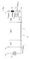
- The invention will be described in the following by way of example only and with reference to the embodiments illustrated in the drawing, in which:
- Fig. 1
- is a circuit diagram illustrating a battery circuit provided with the arrangement of the invention.
- In the drawings,
reference numeral 10 generally denotes an arrangement for reducing electromagnetic fields (EMF) in a vehicle being arranged with a battery. The vehicle can be arranged with the battery in the front or in the rear of the vehicle. - In a preferred embodiment of the invention, the vehicle is arranged with a
battery 12 in the rear, see Fig.1. Thearrangement 10 according the invention then comprises abattery cable 11 leading from the front of the vehicle to a first pole of thebattery 12 in the rear. Preferably, thebattery cable 11 is a positive battery cable and the first pole is a plus pole. In greater detail, thepositive battery cable 11 is generally coupled to a generator in form of analternator 13 as well as the engine cranking motor, the fuse box and other systems requiring or distributing electrical power, the most of which are located in the engine bay or in other areas in the front of the vehicle. Hereinafter, the term "the front" of the vehicle generally relates to the part of the vehicle being located in front of the cabin, e.g. in the engine bay. Furthermore, thepositive battery cable 11 is in its other end coupled to the plus pole of thebattery 12. The charge current Icharge dc+ac of the engine can flow in thepositive battery cable 11 from thealternator 13 to thebattery 12. - A
second battery cable 14 is coupled to a second pole of thebattery 12. Preferably, thesecond battery cable 14 is a negative battery cable and the second pole is a minus pole. Thenegative battery cable 14 is in its other end coupled toground potential 17. In more detail, theground potential 17 is usually constituted of the body of the vehicle, or a part thereof, being located in the rear of vehicle. Hereinafter, the term "the rear" relates to any of the following parts of the vehicle: in the cabin, in the nearness of the cabin, below the cabin, in the trunk or in connection thereto, or even in other areas located laterally to the trunk in the car. The return current Ireturndc+ac of thebattery 12 can flow from thebattery 12 to theground 17 in thenegative battery cable 14. - In the preferred embodiment of the invention,
additional cable 15 is coupled to the minus pole of thebattery 12 as well. Thisadditional cable 15 leads to the front of the vehicle, wherein the return current of thebattery 12 can flow back to the engine bay area. Preferably, the cable for return current 15 is provided close to thepositive battery cable 11 for at least a substantial part of the lengths of thecables positive battery cable 11 and the cable for return current 15 can be arranged substantially in contact or even twisted with each other. It is also possible that thecables cables positive battery cable 11 and the cable for return current 15. - For reducing electromagnetic fields in the vehicle, the
negative battery cable 14 is coupled to ground via a low-pass filter 16. In the preferred embodiment of the invention, the low-pass filter 16 is thus provided coupled between the negative pole of thebattery 12 and its connection to the body of the vehicle. Advantageously, the low-pass filter 16 is constituted of an inductor. - The
arrangement 10 operates in the following way during driving of the vehicle. The charge current Icharge dc+ac flows in thepositive battery cable 11 from the front of the vehicle to thebattery 12 located in the rear. The resulting return current Ireturn dc+ac of thebattery 12 flows from the battery in direction towardground potential 17. Then theinductor 16 gives rise to a division of the return current Iretum de+ac into d.c. (direct current) parts Ireturn dc and a.c. (alternating current) parts Ireturn ac. Preferably, the d.c. part Ireturn dc flows via theinductor 16 through the body to the front of the vehicle, thus keeping the resistance low for this portion of the return current. Then the a.c. part Ireturn ac flows in thecable 15 for return current to the front of the vehicle. Since the a.c. part Ireturn ac is led through the cable for return current 15 being arranged close to thebattery cable 11 instead of through the car body, the electromagnetic fields will be substantially zero or kept at a very low level. Thus, by means of the inventive arrangement, the electromagnetic fields are reduced inside the cabin. - However, it is important that the low-
pass filter 16 in form of the inductor withstands the d.c. charge current Icharge dc without saturating. For operating as a low-pass filter, the inductor has preferably an inductance in the range of 100 to 400 µH, and the low-pass filter has a cut-off frequency of approximately 25 Hz. - Furthermore, for avoiding losses in the windings of the
inductor 16, the number of the winding-turns of theinductor 16 is preferably chosen to be low. As a consequence, the size of the iron core will be bigger than normal in order to minimise the electrical resistance. The number of windings and the size of the iron core should be chosen so that, as mentioned above, the inductor doesn't saturate due to charging current. To reduce the size of the inductor needed to avoid saturation, it is preferable to magnetise the core in opposite direction, using a dc bias secondary winding. - Obviously, it is also possible to apply the arrangement according to the invention in vehicles being arranged with the engine in the rear (e.g. in the trunk), and the battery in the front such as in the engine bay, or in the front part of the cabin. However, in all embodiments of the invention, the
positive battery cable 11 and theadditional cable 15 are arranged to the opposite part of the vehicle, e.g. from the rear to the front of the vehicle, or in the opposite, from the front to the rear of the vehicle (with regard to the direction of the currents). - In the preferred embodiment of the invention described above, the return current of the battery is led to ground potential in two cables, i.e. in the
second battery cable 14 and in theadditional cable 15. However, in other embodiments of the invention, the return current can be led to ground potential in two or more cables. Then the separate cables can be arranged with low-pass filters in different arrangements. - The invention has been described above and illustrated in the drawings by way of example only and the skilled person will recognise that various modifications may be made without departing from the scope of the invention as defined by the appended claims.
Claims (9)
- An arrangement (10) for reducing electromagnetic fields in a vehicle being arranged with a battery (12) mounted in a first end of said vehicle, the arrangement (10) comprising a first battery cable (11) leading from the second end of said vehicle to a first pole of said battery (12), a second pole of said battery (12) being arranged with a second battery cable (14) coupled to ground (17),
characterised in that the second battery cable (14) is coupled to ground (17) at the first end of the vehicle, and that an additional cable (15) is coupled to said second pole of said battery (12) and leading to said second end where it is coupled to ground (17). - An arrangement as claimed in claim 1,
characterised in that said second battery cable (14) is coupled to ground (17) via a low-pass filter (16). - An arrangement as claimed in claim 2,
characterised in that the low-pass filter (16) divides the return current of the battery (12) into d.c. (direct current) parts and a.c. (alternating current) parts, whereof the d.c. part flows in the body from the battery (12) to the opposite part of the vehicle, and the a.c. part flows to the opposite part of the vehicle in the additional cable (15). - An arrangement as claimed in claim 2 or 3,
characterised in that the low-pass filter (16) comprises an inductor. - An arrangement as claimed in any of claims 1 to 4,
characterised in that said additional cable (15) is arranged close to the first battery cable (11) for at least a substantial portion of the length of said first battery cable (11). - An arrangement as claimed in any of the preceding claims,
characterised in that the first pole is a plus pole and that the second pole is a minus pole. - An arrangement as claimed in claim 6,
characterised in that the first battery cable (11) is a positive battery cable and that the second battery cable (14) is a negative battery cable. - An arrangement as claimed in any of the preceding claims,
characterised in that the first end is the rear or of said vehicle and the second end is the front of said vehicle. - A vehicle comprising an arrangement (10) for reducing electromagnetic fields, said vehicle being arranged with a battery (12) in the rear, said arrangement (10) comprising a first battery cable (11) leading from the second end of said vehicle to a first pole of said battery (12), a second pole of said battery (12) being arranged with a second battery cable (14) coupled to ground (17),
characterised in that the second battery cable (14) is coupled to ground (17) at the first end of the vehicle, and that an additional cable (15) is coupled to said second pole of said battery (12) and leading to said second end where it is coupled to ground (17).
Priority Applications (2)
| Application Number | Priority Date | Filing Date | Title |
|---|---|---|---|
| DE2003604674 DE60304674T2 (en) | 2003-03-13 | 2003-03-13 | battery assembly |
| EP20030005380 EP1457389B1 (en) | 2003-03-13 | 2003-03-13 | A battery arrangement |
Applications Claiming Priority (1)
| Application Number | Priority Date | Filing Date | Title |
|---|---|---|---|
| EP20030005380 EP1457389B1 (en) | 2003-03-13 | 2003-03-13 | A battery arrangement |
Publications (2)
| Publication Number | Publication Date |
|---|---|
| EP1457389A1 true EP1457389A1 (en) | 2004-09-15 |
| EP1457389B1 EP1457389B1 (en) | 2006-04-19 |
Family
ID=32748853
Family Applications (1)
| Application Number | Title | Priority Date | Filing Date |
|---|---|---|---|
| EP20030005380 Expired - Lifetime EP1457389B1 (en) | 2003-03-13 | 2003-03-13 | A battery arrangement |
Country Status (2)
| Country | Link |
|---|---|
| EP (1) | EP1457389B1 (en) |
| DE (1) | DE60304674T2 (en) |
Cited By (1)
| Publication number | Priority date | Publication date | Assignee | Title |
|---|---|---|---|---|
| DE102017119527B4 (en) | 2016-08-26 | 2022-07-07 | Denso Corporation | In-vehicle device comprising an electric drive circuit for suppressing interference radiation |
Citations (4)
| Publication number | Priority date | Publication date | Assignee | Title |
|---|---|---|---|---|
| JPS57159133A (en) * | 1981-03-27 | 1982-10-01 | Nissan Motor Co Ltd | Noise preventing device |
| DE19636816A1 (en) * | 1996-09-11 | 1998-03-12 | Daimler Benz Ag | Cable arrangement for motor vehicle electrics |
| US5986355A (en) * | 1995-06-27 | 1999-11-16 | Ab Volvo | Arrangement and method for reduction of magnetic fields and use thereof |
| EP1014529A2 (en) * | 1998-12-18 | 2000-06-28 | Hitachi, Ltd. | Power supply network apparatus |
-
2003
- 2003-03-13 DE DE2003604674 patent/DE60304674T2/en not_active Expired - Lifetime
- 2003-03-13 EP EP20030005380 patent/EP1457389B1/en not_active Expired - Lifetime
Patent Citations (4)
| Publication number | Priority date | Publication date | Assignee | Title |
|---|---|---|---|---|
| JPS57159133A (en) * | 1981-03-27 | 1982-10-01 | Nissan Motor Co Ltd | Noise preventing device |
| US5986355A (en) * | 1995-06-27 | 1999-11-16 | Ab Volvo | Arrangement and method for reduction of magnetic fields and use thereof |
| DE19636816A1 (en) * | 1996-09-11 | 1998-03-12 | Daimler Benz Ag | Cable arrangement for motor vehicle electrics |
| EP1014529A2 (en) * | 1998-12-18 | 2000-06-28 | Hitachi, Ltd. | Power supply network apparatus |
Non-Patent Citations (1)
| Title |
|---|
| PATENT ABSTRACTS OF JAPAN vol. 006, no. 264 (E - 150) 23 December 1982 (1982-12-23) * |
Cited By (1)
| Publication number | Priority date | Publication date | Assignee | Title |
|---|---|---|---|---|
| DE102017119527B4 (en) | 2016-08-26 | 2022-07-07 | Denso Corporation | In-vehicle device comprising an electric drive circuit for suppressing interference radiation |
Also Published As
| Publication number | Publication date |
|---|---|
| DE60304674T2 (en) | 2007-04-12 |
| EP1457389B1 (en) | 2006-04-19 |
| DE60304674D1 (en) | 2006-05-24 |
Similar Documents
| Publication | Publication Date | Title |
|---|---|---|
| RU2371329C1 (en) | Hybrid vehicle drive | |
| EP1359033B1 (en) | Air conditioner | |
| US11932126B2 (en) | Induction assembly of an induction charging device | |
| US5760507A (en) | Electrical generating system for a motor vehicle | |
| JP2007050887A (en) | Power control unit for vehicles | |
| EP3061643A1 (en) | Vehicle mounting structure of contactless electricity reception device | |
| WO2015045663A1 (en) | Vehicle mounting structure of contactless power reception device | |
| GB2289581A (en) | Alternator and static converter system | |
| CN103210572A (en) | Inverter Integrated Electric Compressor | |
| EP1586487A2 (en) | Power supply apparatus for vehicle | |
| US6798166B2 (en) | Electrical power system for an automobile vehicle | |
| JP2008017630A (en) | Power supply system and vehicle equipped with the same | |
| Khan | Automotive electrical systems: Architecture and components | |
| EP1457389B1 (en) | A battery arrangement | |
| JP6850999B2 (en) | Power supply | |
| EP3683088B1 (en) | Vehicle power supply system | |
| US20020047353A1 (en) | Permanent magnet type AC generator having voltage regulating system | |
| US7830050B2 (en) | Brushless automotive alternator having easily-replaceable protective resistor | |
| EP4624268A1 (en) | Vehicle and vehicle powertrain structure | |
| EP4624266A1 (en) | Vehicle and vehicle powertrain structure | |
| US20250303847A1 (en) | Vehicle powertrain structure | |
| US20250381831A1 (en) | Perfected battery for vehicles, kit and method for the conversion of an endothermic vehicle to a hybrid vehicle | |
| JPH0646507A (en) | Electric vehicle electrical system | |
| JP2001304081A (en) | Simultaneous ignition coil for internal combustion engine | |
| JP2001355554A (en) | Simultaneous ignition coil for internal combustion engine |
Legal Events
| Date | Code | Title | Description |
|---|---|---|---|
| PUAI | Public reference made under article 153(3) epc to a published international application that has entered the european phase |
Free format text: ORIGINAL CODE: 0009012 |
|
| AK | Designated contracting states |
Kind code of ref document: A1 Designated state(s): AT BE BG CH CY CZ DE DK EE ES FI FR GB GR HU IE IT LI LU MC NL PT SE SI SK TR |
|
| AX | Request for extension of the european patent |
Extension state: AL LT LV MK RO |
|
| 17P | Request for examination filed |
Effective date: 20050315 |
|
| AKX | Designation fees paid |
Designated state(s): DE GB SE |
|
| 17Q | First examination report despatched |
Effective date: 20050517 |
|
| GRAP | Despatch of communication of intention to grant a patent |
Free format text: ORIGINAL CODE: EPIDOSNIGR1 |
|
| GRAS | Grant fee paid |
Free format text: ORIGINAL CODE: EPIDOSNIGR3 |
|
| GRAA | (expected) grant |
Free format text: ORIGINAL CODE: 0009210 |
|
| AK | Designated contracting states |
Kind code of ref document: B1 Designated state(s): DE GB SE |
|
| REG | Reference to a national code |
Ref country code: GB Ref legal event code: FG4D |
|
| RAP2 | Party data changed (patent owner data changed or rights of a patent transferred) |
Owner name: FORD GLOBAL TECHNOLOGIES, LLC. |
|
| REF | Corresponds to: |
Ref document number: 60304674 Country of ref document: DE Date of ref document: 20060524 Kind code of ref document: P |
|
| REG | Reference to a national code |
Ref country code: SE Ref legal event code: TRGR |
|
| PLBE | No opposition filed within time limit |
Free format text: ORIGINAL CODE: 0009261 |
|
| STAA | Information on the status of an ep patent application or granted ep patent |
Free format text: STATUS: NO OPPOSITION FILED WITHIN TIME LIMIT |
|
| 26N | No opposition filed |
Effective date: 20070122 |
|
| REG | Reference to a national code |
Ref country code: GB Ref legal event code: 732E Free format text: REGISTERED BETWEEN 20111020 AND 20111025 |
|
| REG | Reference to a national code |
Ref country code: DE Ref legal event code: R081 Ref document number: 60304674 Country of ref document: DE Owner name: VOLVO CAR CORPORATION, SE Free format text: FORMER OWNER: FORD GLOBAL TECHNOLOGIES, LLC, DEARBORN, MICH., US Effective date: 20120207 |
|
| PGFP | Annual fee paid to national office [announced via postgrant information from national office to epo] |
Ref country code: DE Payment date: 20130320 Year of fee payment: 11 Ref country code: SE Payment date: 20130321 Year of fee payment: 11 Ref country code: GB Payment date: 20130321 Year of fee payment: 11 |
|
| REG | Reference to a national code |
Ref country code: DE Ref legal event code: R119 Ref document number: 60304674 Country of ref document: DE |
|
| REG | Reference to a national code |
Ref country code: SE Ref legal event code: EUG |
|
| GBPC | Gb: european patent ceased through non-payment of renewal fee |
Effective date: 20140313 |
|
| PG25 | Lapsed in a contracting state [announced via postgrant information from national office to epo] |
Ref country code: SE Free format text: LAPSE BECAUSE OF NON-PAYMENT OF DUE FEES Effective date: 20140314 |
|
| REG | Reference to a national code |
Ref country code: DE Ref legal event code: R119 Ref document number: 60304674 Country of ref document: DE Effective date: 20141001 |
|
| PG25 | Lapsed in a contracting state [announced via postgrant information from national office to epo] |
Ref country code: GB Free format text: LAPSE BECAUSE OF NON-PAYMENT OF DUE FEES Effective date: 20140313 Ref country code: DE Free format text: LAPSE BECAUSE OF NON-PAYMENT OF DUE FEES Effective date: 20141001 |