EP1457348A1 - Device for grounding a printer film - Google Patents
Device for grounding a printer film Download PDFInfo
- Publication number
- EP1457348A1 EP1457348A1 EP04290642A EP04290642A EP1457348A1 EP 1457348 A1 EP1457348 A1 EP 1457348A1 EP 04290642 A EP04290642 A EP 04290642A EP 04290642 A EP04290642 A EP 04290642A EP 1457348 A1 EP1457348 A1 EP 1457348A1
- Authority
- EP
- European Patent Office
- Prior art keywords
- electrically conducting
- roller
- printer film
- printer
- film
- Prior art date
- Legal status (The legal status is an assumption and is not a legal conclusion. Google has not performed a legal analysis and makes no representation as to the accuracy of the status listed.)
- Granted
Links
Images

Classifications
-
- B—PERFORMING OPERATIONS; TRANSPORTING
- B41—PRINTING; LINING MACHINES; TYPEWRITERS; STAMPS
- B41J—TYPEWRITERS; SELECTIVE PRINTING MECHANISMS, i.e. MECHANISMS PRINTING OTHERWISE THAN FROM A FORME; CORRECTION OF TYPOGRAPHICAL ERRORS
- B41J29/00—Details of, or accessories for, typewriters or selective printing mechanisms not otherwise provided for
- B41J29/02—Framework
Definitions
- This invention relates to a device for grounding a printer film or the like which extends from an unwinding roller to a winding roller and is wound at least partially on the unwinding roller and/or the winding roller.
- Printer films may be used in fax machines, printers or the like, where the printer film comes in contact with paper to be printed in a printing operation and then is separated from this paper. In this separation of the paper from the printer film, a separation of charges often occurs, causing the printer film to become charged. To prevent the development of a high voltage and unwanted sparking, which could destroy circuits and the like, the printer film may be grounded so that charges are balanced.
- grounded brushes or the like may be arranged in the area of a print head.
- These brushes have the disadvantage that their bristles may be ripped out because of wear and/or they may clump together, thus having a negative effect on the electric contact between the bristles and the printer film and may result in inadequate grounding and a buildup of charge on the printer film.
- the brushes are usually situated on the side of the printer film which is opposite the side where the charge separation occurs. Therefore, the entire printer film must be electrically conducting.
- Another disadvantage is that the brushes can scrape off part of a coating on the printer film, which thus results in soiling of the machine. Therefore, complex service and/or maintenance work may be required.
- the object of the present invention is therefore to provide a device for grounding of the type defined in the preamble whereby the known disadvantages are avoided and reliable and long-lasting grounding of the printer film is ensured.
- Another object of this invention is to provide a device for grounding which has a simple design and can be manufactured inexpensively.
- the unwinding roller and/or the winding roller is/are connectable at least to an electrically conducting flange which contacts the printer film, and the electrically conducting flange may be brought into engagement with a grounded pick-up element.
- the device according to this invention for grounding at the point of contact with the printer film may be designed to be stationary relative to it, thereby effectively preventing any abrasion of the coating.
- the pick-up element may be connected to the unwinding roller and may also function as a braking device at the same time.
- the electrically conducting flange may contact a coated side of the printer film. It is therefore sufficient if the coating on the printer film is electrically conducting. The coating also contacts the paper to be printed so that the charge separation occurs on the coating. In this embodiment it is not necessary for the backing film of the printer film, which carries the coating to be electrically conducting.
- the electrically conducting flange in another embodiment, it is possible for the electrically conducting flange to include a disk element and for the pick-up element to be designed so that it can be brought into engagement with the outer edge of the disk element.
- the force acting between the pick-up element and the flange acts essentially perpendicular to the axial direction of the roller. When the direction of force is in the axial direction, a support must be provided. This pick-up element may also be used to position the roller.
- the pick-up element prefferably be designed as a braking device for the unwinding roller. Therefore a minimum tension may be ensured in the printer film between the unwinding roller and the winding roller without any additional components.
- the electrically conducting flange may be made of plastic. This constitutes a simple embodiment of the electrically conducting flange, which is inexpensive to manufacture.
- Grounded brushes 8 which prevent a charge from building up on the printer film 1 are situated in the direction of movement of the printer film 1 downstream from the print head 71.
- Fig. 2 shows schematically one embodiment of a device according to this invention for grounding a printer film 1 or the like, where the printer film 1 extends partially from the unwinding roller 2 to the winding roller 3 and is partially wound on the unwinding roller 2 and/or the winding roller 3.
- the print head 71 and the printer roller 72 are situated between the unwinding roller 2 and the winding roller 3.
- an electrically conducting flange 4 is provided, this flange being connectable to the unwinding roller 2 and/or the winding roller 3 and contacting printer film 1.
- the electrically conducting flange 4 can be brought into engagement with a grounded pick-up element 6.
- the electrically conducting flange 4 may be connected to the unwinding roller 2 and/or the winding roller 3, and it is also possible to provide two or more electrically conducting flanges 4. Therefore, a charge balancing of the printer film can be ensured and the development of high voltages may be reliably prevented.
- Additional flanges 5 may be designed to be electrically conducting or electrically insulating.
- the electrically conducting flange 4 may included a disk element 42. It seems expedient if the pick-up element 6 can be brought into engagement with the outer edge 43 of the disk element 42. If the pick-up element 6 presses on a side of the electrically conducting flange 4, then a supporting element is to be provided in the axial direction of the base body 21. This is not necessary with an essentially radial load, so that the support of the unwinding roller 2 can absorb these forces. If the pick-up element 6 has lateral guides or something similar, an alignment of the unwinding roller 2 by means of the pick-up element 6 may also be achieved.
- the pick-up element 6 Due to the grinding abrasion of the pick-up element 6 with the electrically conducting flange 4 in rotation of the electrically conducting flange 4, the latter is decelerated. If the pick-up element 6 is designed as a braking device for the unwinding roller 2, a minimum voltage may be ensured in the printer film 1 between the unwinding roller 2 and the winding roller 3, in particular between the unwinding roller 2 and the printer roller 72.
Landscapes
- Accessory Devices And Overall Control Thereof (AREA)
- Elimination Of Static Electricity (AREA)
Abstract
Description
- This invention relates to a device for grounding a printer film or the like which extends from an unwinding roller to a winding roller and is wound at least partially on the unwinding roller and/or the winding roller.
- Printer films may be used in fax machines, printers or the like, where the printer film comes in contact with paper to be printed in a printing operation and then is separated from this paper. In this separation of the paper from the printer film, a separation of charges often occurs, causing the printer film to become charged. To prevent the development of a high voltage and unwanted sparking, which could destroy circuits and the like, the printer film may be grounded so that charges are balanced.
- In the case of such known devices for grounding a printer film, it is known that grounded brushes or the like may be arranged in the area of a print head. These brushes have the disadvantage that their bristles may be ripped out because of wear and/or they may clump together, thus having a negative effect on the electric contact between the bristles and the printer film and may result in inadequate grounding and a buildup of charge on the printer film. The brushes are usually situated on the side of the printer film which is opposite the side where the charge separation occurs. Therefore, the entire printer film must be electrically conducting. Another disadvantage is that the brushes can scrape off part of a coating on the printer film, which thus results in soiling of the machine. Therefore, complex service and/or maintenance work may be required.
- The object of the present invention is therefore to provide a device for grounding of the type defined in the preamble whereby the known disadvantages are avoided and reliable and long-lasting grounding of the printer film is ensured. Another object of this invention is to provide a device for grounding which has a simple design and can be manufactured inexpensively.
- According to this invention, this is achieved by the fact that the unwinding roller and/or the winding roller is/are connectable at least to an electrically conducting flange which contacts the printer film, and the electrically conducting flange may be brought into engagement with a grounded pick-up element.
- This yields the advantage that the device according to this invention for grounding at the point of contact with the printer film may be designed to be stationary relative to it, thereby effectively preventing any abrasion of the coating. In addition, the pick-up element may be connected to the unwinding roller and may also function as a braking device at the same time.
- In a refinement of this invention it is possible for the unwinding roller and/or the winding roller to have an essentially tubular design, having a slotted recess in the longitudinal direction on at least one end so that a projection or the like of the electrically conducting flange may engage in the slotted recess. Therefore, a rotationally fixed connection between the electrically conducting flange and the printer film wound onto the roller can be achieved in a simple way.
- According to another embodiment of this invention, the electrically conducting flange may contact a coated side of the printer film. It is therefore sufficient if the coating on the printer film is electrically conducting. The coating also contacts the paper to be printed so that the charge separation occurs on the coating. In this embodiment it is not necessary for the backing film of the printer film, which carries the coating to be electrically conducting.
- In another embodiment of this invention, it is possible for the electrically conducting flange to include a disk element and for the pick-up element to be designed so that it can be brought into engagement with the outer edge of the disk element. The force acting between the pick-up element and the flange acts essentially perpendicular to the axial direction of the roller. When the direction of force is in the axial direction, a support must be provided. This pick-up element may also be used to position the roller.
- According to another embodiment of this invention it is possible to provide for the pick-up element to be designed as a braking device for the unwinding roller. Therefore a minimum tension may be ensured in the printer film between the unwinding roller and the winding roller without any additional components.
- In another embodiment of this invention, the electrically conducting flange may be made of plastic. This constitutes a simple embodiment of the electrically conducting flange, which is inexpensive to manufacture.
- This invention will now be described in greater detail with reference to the accompanying drawings, which illustrate exemplary embodiments. They show:
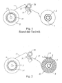
- Fig. 1 a schematic side view of a device known from the state of the art for grounding a printer film with brushes;
- Fig. 2 shows a schematic side view of an exemplary embodiment of a device according to this invention for grounding a printer film or the like;
- Fig. 3 shows a partially cutaway oblique view of an electrically conducting flange; and
- Fig. 4 shows an oblique view of an unwinding roller.
-
- Fig. 1 shows a device for grounding a
printer film 1.Such printer films 1 may be used in fax machines, printers or the like, where theprinter film 1 comes in contact with paper to be printed between theprint head 71 and theprinter roller 72 and the printing operation and then the printer film is separated from this paper. In this separation of the paper from theprinter film 1, a charge separation often occurs so that theprinter film 1 develops a charge. To avoid the development of high voltages and unwanted sparking so that circuits or the like may be destroyed in particular, theprinter film 1 may be grounded to ensure a balancing of the charge. Theprinter film 1 extends partially from anunwinding roller 2 to a windingroller 3 and is partially wound on theunwinding roller 2 and/or the windingroller 3. Between theunwinding roller 2 and thewinding roller 3 there is aprint head 71 and aprinter roller 72. Groundedbrushes 8 which prevent a charge from building up on theprinter film 1 are situated in the direction of movement of theprinter film 1 downstream from theprint head 71. - Fig. 2 shows schematically one embodiment of a device according to this invention for grounding a
printer film 1 or the like, where theprinter film 1 extends partially from theunwinding roller 2 to thewinding roller 3 and is partially wound on theunwinding roller 2 and/or thewinding roller 3. Theprint head 71 and theprinter roller 72 are situated between theunwinding roller 2 and the windingroller 3. - In addition, an electrically conducting
flange 4 is provided, this flange being connectable to theunwinding roller 2 and/or thewinding roller 3 and contactingprinter film 1. The electrically conductingflange 4 can be brought into engagement with a grounded pick-up element 6. The electrically conductingflange 4 may be connected to theunwinding roller 2 and/or the windingroller 3, and it is also possible to provide two or more electrically conductingflanges 4. Therefore, a charge balancing of the printer film can be ensured and the development of high voltages may be reliably prevented.Additional flanges 5 may be designed to be electrically conducting or electrically insulating. - As shown in Fig. 2, at least one of
flanges winding roller 3 may have a rotationally fixed connection to adrive wheel 31 so thatwinding roller 3 can be driven. - Fig. 4 shows the
unwinding roller 2 schematically, showing that it has an essentiallytubular base body 21, which is designed with aslotted recess 22 in the longitudinal direction of thebase body 21. Thewinding roller 3 may have a similar design. - Fig. 3 shows an embodiment of the electrically conducting
flange 4, which has aprojection 21 that engages in theslotted recess 22 and contacts theprinter film 1 which is wound around thebase body 21. - The electrically conducting
flange 4 may included adisk element 42. It seems expedient if the pick-up element 6 can be brought into engagement with theouter edge 43 of thedisk element 42. If the pick-up element 6 presses on a side of the electrically conductingflange 4, then a supporting element is to be provided in the axial direction of thebase body 21. This is not necessary with an essentially radial load, so that the support of theunwinding roller 2 can absorb these forces. If the pick-up element 6 has lateral guides or something similar, an alignment of theunwinding roller 2 by means of the pick-up element 6 may also be achieved. - Due to the grinding abrasion of the pick-up element 6 with the electrically conducting
flange 4 in rotation of the electrically conductingflange 4, the latter is decelerated. If the pick-up element 6 is designed as a braking device for theunwinding roller 2, a minimum voltage may be ensured in theprinter film 1 between theunwinding roller 2 and thewinding roller 3, in particular between theunwinding roller 2 and theprinter roller 72. - The electrically conducting
flange 4 can be manufactured easily and inexpensively if it is made of plastic. - The charge balancing of the
printer film 1 may be achieved if the electrically conducting flange is connected to theunwinding roller 2 and/or thewinding roller 3. Theprinter film 1 is preferably wound up so that the coatedside 11 comes to lie on the inside. Therefore, contacting of theprojection 41 with the coatedside 11 of theprinter film 1 can be ensured in a simple way. Usually the coatedside 11 of the printer film is arranged on the inside on theunwinding roller 2.
Claims (6)
- A device for grounding a printer film (1) or the like which extends from an unwinding roller (2) to a winding roller (3) and is wound at least partially on the unwinding roller (2) and/or the winding roller (3), characterized in that the unwinding (2) and/or the winding roller (3) can be brought into contact at least with an electrically conducting flange (4) which contacts the printer film (1), and the electrically conducting flange (4) can be brought into engagement with the grounded pick-up element (6).
- The device according to Claim 1, characterized in that the unwinding roller (2) and/or the winding roller (3) is/are designed to be essentially tubular and to have a slotted recess (22) running in the longitudinal direction on at least one end so that a projection (41) or the like on the electrically conducting flange (4) engages in this slotted recess.
- The device according to Claim 1 or 2, characterized in that the electrically conducting flange (4) contacts a coated side (11) of the printer film (1).
- The device according to Claim 1, 2 or 3, characterized in that the electrically conducting flange (4) includes a disk element (42) and the pick-up element (6) can be brought into engagement with the edge (43) of the disk element (42) situated on the outside.
- The device according to one of Claims 1 through 4, characterized in that the pick-up element (6) is designed as a braking device for the unwinding roller (2) .
- The device according to one of Claims 1 through 5,
characterized in that the electrically conducting flange (4) is made of plastic.
Applications Claiming Priority (2)
| Application Number | Priority Date | Filing Date | Title |
|---|---|---|---|
| AT3662003 | 2003-03-10 | ||
| AT3662003A ATA3662003A (en) | 2003-03-10 | 2003-03-10 | DEVICE FOR GROUNDING A PRINTER FILM |
Publications (2)
| Publication Number | Publication Date |
|---|---|
| EP1457348A1 true EP1457348A1 (en) | 2004-09-15 |
| EP1457348B1 EP1457348B1 (en) | 2007-11-28 |
Family
ID=29588418
Family Applications (1)
| Application Number | Title | Priority Date | Filing Date |
|---|---|---|---|
| EP20040290642 Expired - Lifetime EP1457348B1 (en) | 2003-03-10 | 2004-03-10 | Device for grounding a printer film |
Country Status (4)
| Country | Link |
|---|---|
| EP (1) | EP1457348B1 (en) |
| AT (1) | ATA3662003A (en) |
| DE (1) | DE602004010322T2 (en) |
| ES (1) | ES2295793T3 (en) |
Families Citing this family (1)
| Publication number | Priority date | Publication date | Assignee | Title |
|---|---|---|---|---|
| JP2019169410A (en) * | 2018-03-26 | 2019-10-03 | コニカミノルタ株式会社 | Charging adjustment device and image forming apparatus |
Citations (6)
| Publication number | Priority date | Publication date | Assignee | Title |
|---|---|---|---|---|
| JPS57148682A (en) * | 1981-03-09 | 1982-09-14 | Canon Inc | Ink ribbon delivery mechanism |
| JPS61120784A (en) * | 1984-11-15 | 1986-06-07 | Minolta Camera Co Ltd | Heat transfer printer |
| JPS61154964A (en) * | 1984-12-28 | 1986-07-14 | Victor Co Of Japan Ltd | Printer apparatus |
| US4893134A (en) * | 1987-09-04 | 1990-01-09 | Minolta Camera Kabushiki Kaisha | Thermal transfer recording apparatus |
| US5169247A (en) * | 1988-06-02 | 1992-12-08 | Canon Kabushiki Kaisha | Thermal printer with biaxial motor feed of the carriage and ribbon |
| US5533819A (en) * | 1986-02-12 | 1996-07-09 | Canon Kabushiki Kaisha | Character by character thermal recording device with ink sheet feed control |
-
2003
- 2003-03-10 AT AT3662003A patent/ATA3662003A/en not_active Application Discontinuation
-
2004
- 2004-03-10 ES ES04290642T patent/ES2295793T3/en not_active Expired - Lifetime
- 2004-03-10 EP EP20040290642 patent/EP1457348B1/en not_active Expired - Lifetime
- 2004-03-10 DE DE200460010322 patent/DE602004010322T2/en not_active Expired - Lifetime
Patent Citations (6)
| Publication number | Priority date | Publication date | Assignee | Title |
|---|---|---|---|---|
| JPS57148682A (en) * | 1981-03-09 | 1982-09-14 | Canon Inc | Ink ribbon delivery mechanism |
| JPS61120784A (en) * | 1984-11-15 | 1986-06-07 | Minolta Camera Co Ltd | Heat transfer printer |
| JPS61154964A (en) * | 1984-12-28 | 1986-07-14 | Victor Co Of Japan Ltd | Printer apparatus |
| US5533819A (en) * | 1986-02-12 | 1996-07-09 | Canon Kabushiki Kaisha | Character by character thermal recording device with ink sheet feed control |
| US4893134A (en) * | 1987-09-04 | 1990-01-09 | Minolta Camera Kabushiki Kaisha | Thermal transfer recording apparatus |
| US5169247A (en) * | 1988-06-02 | 1992-12-08 | Canon Kabushiki Kaisha | Thermal printer with biaxial motor feed of the carriage and ribbon |
Non-Patent Citations (3)
| Title |
|---|
| PATENT ABSTRACTS OF JAPAN vol. 0062, no. 53 (M - 178) 11 December 1982 (1982-12-11) * |
| PATENT ABSTRACTS OF JAPAN vol. 0103, no. 07 (M - 527) 18 October 1986 (1986-10-18) * |
| PATENT ABSTRACTS OF JAPAN vol. 0103, no. 57 (M - 540) 2 December 1986 (1986-12-02) * |
Also Published As
| Publication number | Publication date |
|---|---|
| EP1457348B1 (en) | 2007-11-28 |
| DE602004010322T2 (en) | 2008-10-16 |
| ES2295793T3 (en) | 2008-04-16 |
| ATA3662003A (en) | 2003-12-15 |
| DE602004010322D1 (en) | 2008-01-10 |
Similar Documents
| Publication | Publication Date | Title |
|---|---|---|
| KR100346713B1 (en) | Paper separating apparatus for printer | |
| US5758247A (en) | Charge removing device for electrophotographic printer | |
| EP1457348B1 (en) | Device for grounding a printer film | |
| US5579093A (en) | Resiliently biased end caps for photoconductive drums | |
| JP2000219347A (en) | Sheet feeding apparatus and image forming apparatus having the same | |
| EP1231522B1 (en) | Latent image carrier and image forming apparatus | |
| JP3097872B2 (en) | Paper cutting equipment | |
| JP5127693B2 (en) | Torque limiter, sheet separation mechanism, and image forming apparatus | |
| JP2001341881A (en) | Sheet transport device | |
| US20120069078A1 (en) | Inkjet recording apparatus and inkjet recording method | |
| JP4180880B2 (en) | Charging roller | |
| JP3337580B2 (en) | Transfer belt cleaning device | |
| KR100402796B1 (en) | Apparatus for feeding paper having electrostatic removing means | |
| JP3274925B2 (en) | Roll paper end detection device | |
| JPH09110201A (en) | Paper feeder | |
| JPH11180020A (en) | Printing equipment | |
| JP4442134B2 (en) | Waste toner conveying apparatus and image forming apparatus | |
| JP3611922B2 (en) | Paper transport device | |
| JPS6351428B2 (en) | ||
| JP2687985B2 (en) | Image forming device | |
| KR200162007Y1 (en) | Paper Jam Removal Device of Printer | |
| JP5169514B2 (en) | Image forming apparatus | |
| KR200169761Y1 (en) | Image forming apparatus | |
| US7721859B2 (en) | Rotary force controlling apparatus and image forming apparatus including the same | |
| JP4634853B2 (en) | Image forming apparatus |
Legal Events
| Date | Code | Title | Description |
|---|---|---|---|
| PUAI | Public reference made under article 153(3) epc to a published international application that has entered the european phase |
Free format text: ORIGINAL CODE: 0009012 |
|
| AK | Designated contracting states |
Kind code of ref document: A1 Designated state(s): AT BE BG CH CY CZ DE DK EE ES FI FR GB GR HU IE IT LI LU MC NL PL PT RO SE SI SK TR |
|
| AX | Request for extension of the european patent |
Extension state: AL HR LT LV MK |
|
| 17P | Request for examination filed |
Effective date: 20050314 |
|
| AKX | Designation fees paid |
Designated state(s): AT DE ES FR GB IT |
|
| RAP1 | Party data changed (applicant data changed or rights of an application transferred) |
Owner name: SAGEM COMMUNICATION |
|
| GRAP | Despatch of communication of intention to grant a patent |
Free format text: ORIGINAL CODE: EPIDOSNIGR1 |
|
| GRAS | Grant fee paid |
Free format text: ORIGINAL CODE: EPIDOSNIGR3 |
|
| GRAA | (expected) grant |
Free format text: ORIGINAL CODE: 0009210 |
|
| AK | Designated contracting states |
Kind code of ref document: B1 Designated state(s): AT DE ES FR GB IT |
|
| REG | Reference to a national code |
Ref country code: GB Ref legal event code: FG4D |
|
| REF | Corresponds to: |
Ref document number: 602004010322 Country of ref document: DE Date of ref document: 20080110 Kind code of ref document: P |
|
| REG | Reference to a national code |
Ref country code: ES Ref legal event code: FG2A Ref document number: 2295793 Country of ref document: ES Kind code of ref document: T3 |
|
| ET | Fr: translation filed | ||
| PLBE | No opposition filed within time limit |
Free format text: ORIGINAL CODE: 0009261 |
|
| STAA | Information on the status of an ep patent application or granted ep patent |
Free format text: STATUS: NO OPPOSITION FILED WITHIN TIME LIMIT |
|
| 26N | No opposition filed |
Effective date: 20080829 |
|
| REG | Reference to a national code |
Ref country code: FR Ref legal event code: TP Owner name: SAGEMCOM DOCUMENTS SAS, FR Effective date: 20111005 |
|
| REG | Reference to a national code |
Ref country code: DE Ref legal event code: R082 Ref document number: 602004010322 Country of ref document: DE |
|
| REG | Reference to a national code |
Ref country code: DE Ref legal event code: R081 Ref document number: 602004010322 Country of ref document: DE Owner name: SAGEMCOM SAS, FR Free format text: FORMER OWNER: SAGEM COMMUNICATION, PARIS, FR Effective date: 20130617 |
|
| REG | Reference to a national code |
Ref country code: FR Ref legal event code: PLFP Year of fee payment: 12 |
|
| PGFP | Annual fee paid to national office [announced via postgrant information from national office to epo] |
Ref country code: DE Payment date: 20150219 Year of fee payment: 12 Ref country code: ES Payment date: 20150309 Year of fee payment: 12 Ref country code: IT Payment date: 20150219 Year of fee payment: 12 |
|
| PGFP | Annual fee paid to national office [announced via postgrant information from national office to epo] |
Ref country code: GB Payment date: 20150226 Year of fee payment: 12 Ref country code: FR Payment date: 20150319 Year of fee payment: 12 Ref country code: AT Payment date: 20150220 Year of fee payment: 12 |
|
| REG | Reference to a national code |
Ref country code: DE Ref legal event code: R119 Ref document number: 602004010322 Country of ref document: DE |
|
| REG | Reference to a national code |
Ref country code: AT Ref legal event code: MM01 Ref document number: 379546 Country of ref document: AT Kind code of ref document: T Effective date: 20160310 |
|
| GBPC | Gb: european patent ceased through non-payment of renewal fee |
Effective date: 20160310 |
|
| REG | Reference to a national code |
Ref country code: FR Ref legal event code: ST Effective date: 20161130 |
|
| PG25 | Lapsed in a contracting state [announced via postgrant information from national office to epo] |
Ref country code: DE Free format text: LAPSE BECAUSE OF NON-PAYMENT OF DUE FEES Effective date: 20161001 Ref country code: FR Free format text: LAPSE BECAUSE OF NON-PAYMENT OF DUE FEES Effective date: 20160331 Ref country code: GB Free format text: LAPSE BECAUSE OF NON-PAYMENT OF DUE FEES Effective date: 20160310 |
|
| PG25 | Lapsed in a contracting state [announced via postgrant information from national office to epo] |
Ref country code: AT Free format text: LAPSE BECAUSE OF NON-PAYMENT OF DUE FEES Effective date: 20160310 Ref country code: IT Free format text: LAPSE BECAUSE OF NON-PAYMENT OF DUE FEES Effective date: 20160310 |
|
| REG | Reference to a national code |
Ref country code: ES Ref legal event code: FD2A Effective date: 20170428 |
|
| PG25 | Lapsed in a contracting state [announced via postgrant information from national office to epo] |
Ref country code: ES Free format text: LAPSE BECAUSE OF NON-PAYMENT OF DUE FEES Effective date: 20160311 |