EP1456894B1 - Electrochemical cell having venting current collector and seal assembly - Google Patents
Electrochemical cell having venting current collector and seal assembly Download PDFInfo
- Publication number
- EP1456894B1 EP1456894B1 EP02797287A EP02797287A EP1456894B1 EP 1456894 B1 EP1456894 B1 EP 1456894B1 EP 02797287 A EP02797287 A EP 02797287A EP 02797287 A EP02797287 A EP 02797287A EP 1456894 B1 EP1456894 B1 EP 1456894B1
- Authority
- EP
- European Patent Office
- Prior art keywords
- current collector
- electrochemical cell
- seal member
- seal
- collector
- Prior art date
- Legal status (The legal status is an assumption and is not a legal conclusion. Google has not performed a legal analysis and makes no representation as to the accuracy of the status listed.)
- Expired - Lifetime
Links
- 238000013022 venting Methods 0.000 title claims abstract description 20
- 239000007789 gas Substances 0.000 claims abstract description 35
- 238000007789 sealing Methods 0.000 claims abstract description 17
- 239000000463 material Substances 0.000 claims description 11
- 239000003792 electrolyte Substances 0.000 claims description 6
- -1 polypropylene Polymers 0.000 claims description 4
- 239000004743 Polypropylene Substances 0.000 claims description 3
- 229920001155 polypropylene Polymers 0.000 claims description 3
- 230000008878 coupling Effects 0.000 claims description 2
- 238000010168 coupling process Methods 0.000 claims description 2
- 238000005859 coupling reaction Methods 0.000 claims description 2
- 230000000717 retained effect Effects 0.000 claims 1
- 229910000831 Steel Inorganic materials 0.000 description 20
- 239000010959 steel Substances 0.000 description 20
- 230000000712 assembly Effects 0.000 description 9
- 238000000429 assembly Methods 0.000 description 9
- 230000036961 partial effect Effects 0.000 description 9
- KWYUFKZDYYNOTN-UHFFFAOYSA-M Potassium hydroxide Chemical compound [OH-].[K+] KWYUFKZDYYNOTN-UHFFFAOYSA-M 0.000 description 8
- 230000002829 reductive effect Effects 0.000 description 7
- NUJOXMJBOLGQSY-UHFFFAOYSA-N manganese dioxide Chemical compound O=[Mn]=O NUJOXMJBOLGQSY-UHFFFAOYSA-N 0.000 description 6
- 230000002093 peripheral effect Effects 0.000 description 6
- 239000004727 Noryl Substances 0.000 description 5
- 229920001207 Noryl Polymers 0.000 description 5
- 239000004677 Nylon Substances 0.000 description 5
- 238000013459 approach Methods 0.000 description 5
- 239000004020 conductor Substances 0.000 description 5
- 229920001778 nylon Polymers 0.000 description 5
- HCHKCACWOHOZIP-UHFFFAOYSA-N Zinc Chemical compound [Zn] HCHKCACWOHOZIP-UHFFFAOYSA-N 0.000 description 4
- 238000013461 design Methods 0.000 description 4
- 230000006835 compression Effects 0.000 description 3
- 238000007906 compression Methods 0.000 description 3
- 230000003247 decreasing effect Effects 0.000 description 3
- 239000011262 electrochemically active material Substances 0.000 description 3
- 230000007246 mechanism Effects 0.000 description 3
- 239000012528 membrane Substances 0.000 description 3
- 239000011149 active material Substances 0.000 description 2
- 239000000654 additive Substances 0.000 description 2
- 238000005336 cracking Methods 0.000 description 2
- 238000002788 crimping Methods 0.000 description 2
- 230000007423 decrease Effects 0.000 description 2
- 239000008151 electrolyte solution Substances 0.000 description 2
- 238000001746 injection moulding Methods 0.000 description 2
- 229910052751 metal Inorganic materials 0.000 description 2
- 239000002184 metal Substances 0.000 description 2
- 239000004033 plastic Substances 0.000 description 2
- 229920003023 plastic Polymers 0.000 description 2
- 239000011701 zinc Substances 0.000 description 2
- 229910052725 zinc Inorganic materials 0.000 description 2
- OKTJSMMVPCPJKN-UHFFFAOYSA-N Carbon Chemical compound [C] OKTJSMMVPCPJKN-UHFFFAOYSA-N 0.000 description 1
- UFHFLCQGNIYNRP-UHFFFAOYSA-N Hydrogen Chemical compound [H][H] UFHFLCQGNIYNRP-UHFFFAOYSA-N 0.000 description 1
- 239000004698 Polyethylene Substances 0.000 description 1
- 229920006102 Zytel® Polymers 0.000 description 1
- 238000010521 absorption reaction Methods 0.000 description 1
- 230000009471 action Effects 0.000 description 1
- 239000006183 anode active material Substances 0.000 description 1
- 239000010426 asphalt Substances 0.000 description 1
- 239000011324 bead Substances 0.000 description 1
- 230000015572 biosynthetic process Effects 0.000 description 1
- 238000002144 chemical decomposition reaction Methods 0.000 description 1
- 239000011530 conductive current collector Substances 0.000 description 1
- 230000001419 dependent effect Effects 0.000 description 1
- 239000006181 electrochemical material Substances 0.000 description 1
- 239000003349 gelling agent Substances 0.000 description 1
- 239000010439 graphite Substances 0.000 description 1
- 229910002804 graphite Inorganic materials 0.000 description 1
- 238000007373 indentation Methods 0.000 description 1
- 238000002955 isolation Methods 0.000 description 1
- 235000015110 jellies Nutrition 0.000 description 1
- 239000008274 jelly Substances 0.000 description 1
- 230000000670 limiting effect Effects 0.000 description 1
- 238000004519 manufacturing process Methods 0.000 description 1
- 239000011159 matrix material Substances 0.000 description 1
- 238000000034 method Methods 0.000 description 1
- 230000005012 migration Effects 0.000 description 1
- 238000013508 migration Methods 0.000 description 1
- 239000000203 mixture Substances 0.000 description 1
- 239000004745 nonwoven fabric Substances 0.000 description 1
- 239000002245 particle Substances 0.000 description 1
- 239000013618 particulate matter Substances 0.000 description 1
- 230000000737 periodic effect Effects 0.000 description 1
- 239000002985 plastic film Substances 0.000 description 1
- 229920006255 plastic film Polymers 0.000 description 1
- 229920000573 polyethylene Polymers 0.000 description 1
- 229920000642 polymer Polymers 0.000 description 1
- 230000001681 protective effect Effects 0.000 description 1
- 150000003839 salts Chemical class 0.000 description 1
- 239000007787 solid Substances 0.000 description 1
- 239000007921 spray Substances 0.000 description 1
- 239000003351 stiffener Substances 0.000 description 1
- 238000003860 storage Methods 0.000 description 1
- 229920005992 thermoplastic resin Polymers 0.000 description 1
Images


Classifications
-
- H—ELECTRICITY
- H01—ELECTRIC ELEMENTS
- H01M—PROCESSES OR MEANS, e.g. BATTERIES, FOR THE DIRECT CONVERSION OF CHEMICAL ENERGY INTO ELECTRICAL ENERGY
- H01M50/00—Constructional details or processes of manufacture of the non-active parts of electrochemical cells other than fuel cells, e.g. hybrid cells
- H01M50/30—Arrangements for facilitating escape of gases
- H01M50/317—Re-sealable arrangements
- H01M50/325—Re-sealable arrangements comprising deformable valve members, e.g. elastic or flexible valve members
- H01M50/333—Spring-loaded vent valves
-
- H—ELECTRICITY
- H01—ELECTRIC ELEMENTS
- H01M—PROCESSES OR MEANS, e.g. BATTERIES, FOR THE DIRECT CONVERSION OF CHEMICAL ENERGY INTO ELECTRICAL ENERGY
- H01M50/00—Constructional details or processes of manufacture of the non-active parts of electrochemical cells other than fuel cells, e.g. hybrid cells
- H01M50/10—Primary casings; Jackets or wrappings
- H01M50/147—Lids or covers
- H01M50/166—Lids or covers characterised by the methods of assembling casings with lids
- H01M50/171—Lids or covers characterised by the methods of assembling casings with lids using adhesives or sealing agents
-
- H—ELECTRICITY
- H01—ELECTRIC ELEMENTS
- H01M—PROCESSES OR MEANS, e.g. BATTERIES, FOR THE DIRECT CONVERSION OF CHEMICAL ENERGY INTO ELECTRICAL ENERGY
- H01M50/00—Constructional details or processes of manufacture of the non-active parts of electrochemical cells other than fuel cells, e.g. hybrid cells
- H01M50/10—Primary casings; Jackets or wrappings
- H01M50/147—Lids or covers
- H01M50/166—Lids or covers characterised by the methods of assembling casings with lids
- H01M50/167—Lids or covers characterised by the methods of assembling casings with lids by crimping
-
- H—ELECTRICITY
- H01—ELECTRIC ELEMENTS
- H01M—PROCESSES OR MEANS, e.g. BATTERIES, FOR THE DIRECT CONVERSION OF CHEMICAL ENERGY INTO ELECTRICAL ENERGY
- H01M50/00—Constructional details or processes of manufacture of the non-active parts of electrochemical cells other than fuel cells, e.g. hybrid cells
- H01M50/30—Arrangements for facilitating escape of gases
- H01M50/317—Re-sealable arrangements
- H01M50/325—Re-sealable arrangements comprising deformable valve members, e.g. elastic or flexible valve members
-
- H—ELECTRICITY
- H01—ELECTRIC ELEMENTS
- H01M—PROCESSES OR MEANS, e.g. BATTERIES, FOR THE DIRECT CONVERSION OF CHEMICAL ENERGY INTO ELECTRICAL ENERGY
- H01M50/00—Constructional details or processes of manufacture of the non-active parts of electrochemical cells other than fuel cells, e.g. hybrid cells
- H01M50/30—Arrangements for facilitating escape of gases
- H01M50/342—Non-re-sealable arrangements
-
- Y—GENERAL TAGGING OF NEW TECHNOLOGICAL DEVELOPMENTS; GENERAL TAGGING OF CROSS-SECTIONAL TECHNOLOGIES SPANNING OVER SEVERAL SECTIONS OF THE IPC; TECHNICAL SUBJECTS COVERED BY FORMER USPC CROSS-REFERENCE ART COLLECTIONS [XRACs] AND DIGESTS
- Y02—TECHNOLOGIES OR APPLICATIONS FOR MITIGATION OR ADAPTATION AGAINST CLIMATE CHANGE
- Y02E—REDUCTION OF GREENHOUSE GAS [GHG] EMISSIONS, RELATED TO ENERGY GENERATION, TRANSMISSION OR DISTRIBUTION
- Y02E60/00—Enabling technologies; Technologies with a potential or indirect contribution to GHG emissions mitigation
- Y02E60/10—Energy storage using batteries
Definitions
- the present invention generally relates to electrochemical cells (i.e., batteries) comprising a current collector and seal assembly for sealing the open end of a cell container and providing pressure relief for venting gases when exposed to excessive pressure.
- electrochemical cells i.e., batteries
- Conventional alkaline electrochemical cells generally include a steel cylindrical can having a positive electrode, referred to as the cathode, which commonly comprises manganese dioxide as the active materials.
- the electrochemical cell also includes a negative electrode, referred to as the anode, which commonly comprises zinc powder as the active material.
- the cathode is typically formed against the interior surface of the steel can, while the anode is generally centrally disposed in the can.
- a separator is located between the anode and the cathode, and an alkaline electrolyte solution simultaneously contacts the anode, the cathode, and the separator.
- a conductive current collector is inserted into the anode active material to provide an electrical path to a negative outer terminal.
- An annular polymeric (e.g., nylon) seal provides closure to the open end of the steel can to seal the active electrochemical materials in the sealed volume of the can.
- An inner cover radially supports the seal. The current collector, inner cover, and seal are typically assembled together to form a collector and seal assembly.
- Cylindrical alkaline cells are typically sealed closed by placing the collector and seal assembly in the open end of the steel can and crimping the upper end of the can inwardly and over the outer periphery of the seal to compress the seal.
- electrochemical cells commonly employ electrochemically active materials, such as zinc, which generate hydrogen gas, particularly when subjected to abusive discharge conditions, such as battery reversal, as well as during storage, and sometimes during or following service use.
- abusive discharge conditions such as battery reversal
- the can is sealed closed, excessive build-up of high pressure gases within the sealed can may force the crimped closure open and cause damage to the cell and/or the device which the cell is employed.
- One approach to avoiding a potentially excessive build-up of pressure in a cell has been to employ a resealable valve system that periodically releases excessive pressurized gases from within the active cell volume.
- the continued periodic release of pressurized gases may, in some situations, permit the release of electrolyte solution containing salts or other particulate matter, which may foul the resealable valve, and such systems generally require additional costly components.
- Another approach to avoiding excessive build-up of internal pressure involves employing a sealed membrane that is intended to blow out when exposed to excessive pressure either by puncture or rupture of the membrane itself.
- a puncture mechanism such as a spiked member, may be employed to punch a hole in the sealed membrane once the internal pressure reaches a predetermined amount.
- U.S. -A- 5,667,912 discloses a current collector assembly having a seal with a thinned portion formed in the seal diaphragm axisymmetrical about a rotation of the central longitudinal axis of the cell. The thinned portion of the seal is intended to shear when the internal pressure exceeds a predetermined pressure threshold, to thereby create a pressure relief vent passage.
- an electrochemical cell having a collector and seal assembly which comprise a seal member (6) in form of a central hub having an opening, the opening defined by a wall (6d), an axially movable current collector shaft (5) extending through the opening in the seal member (6) such that the seal member sealingly engages the shaft of the current collector when in a sealed position; the axially movable collector shaft can be moved into a vent position upon exposure to a predetermined pressure in a cell container so as to provide a pressure relief passage between the seal member (6) and the collector (5) for venting pressurized gases.
- US-A-3,923,548 discloses a gas valve, in a galvanic cell having a cover and a current conductor extending through the cover, includes a sealing disc located at the cell cover and surrounding the current conductor, the sealing disc having an inner rim gas-tightly engaging the current conductor, at least one part of the inner rim engaging a smooth surface portion of the current conductor and being elastically yieldable under the action of an increased gas pressure within the cell so as to vent the gas.
- EP-A-0327366 discloses a primary cell that has a container comprising a metal can closed by a plastics disc through which a current collector extends. If the pressure inside the container rises to an excessive value, the plastics disc is deformed and the electrical circuit through the cell is opened.
- the present invention improves the protective safeguards of an electrochemical cell with an easy-to-manufacture and low profile collector and seal assembly for sealing the open end of an electrochemical cell container and providing controlled venting of pressurized gases.
- a collector and seal assembly comprising a seal member and a current collector, for sealing the open end of an electrochemical cell container.
- the seal member is adapted to be disposed in an open end of a container to provide a sealed closure to the open end of the container.
- the seal member has an opening therein, with a shaft of the current collector extending therethrough.
- the current collector is interference fit within the opening such that the seal member sealingly engages the shaft of the current collector when irr a sealed position. At least one of the seal member and the current collector is axially movable, relative to the other of the seal member and the current collector, to a vent position upon exposure to a predetermined pressure so as to provide a pressure relief passage for venting pressurized gases.
- Another aspect of the invention is an electrochemical cell comprising such a collector and seal assembly.
- One embodiment of the present invention is an electrochemical cell in which the current collector is axially movable within the opening of the seal member, from the sealed position to the vent position, upon experiencing a predetermined pressure within the cell, so as to provide a pressure relief passage to vent pressurized gases.
- the cell may have a conductive connector (e.g., a coil spring or a bowl-shaped disk), coupling the current collector to an outer cover, that biases the current collector toward the seal member. After venting pressurized gases from the cell, the current collector and seal assembly may be capable of sealingly re-engaging each other.
- Another embodiment of the invention is an electrochemical cell in which the seal member is axially movable along the shaft of the current collector, from the sealed position to the vent position, upon experiencing a predetermined pressure within the cell, so as to provide a pressure relief passage to vent pressurized gases.
- the current collector may have a first diameter and a second diameter, which is less than the first diameter, with the seal member being movable along the shaft, from the first diameter to the second diameter, to provide the pressure relief passage.
- the first diameter may be an enlarged diameter step for retaining the seal in the sealed position, with the central hub of the seal member moveable along the shaft, over the enlarged diameter step, to the vent position.
- the collector may have one or more flutes formed therein for providing the pressure relief passage.
- the seal member may also include a vent path on its top surface to prevent resealing of the current collector and the seal member when in the vent position.
- the present invention relates to an electrochemical cell comprising: a container having a bottom end and an open top end; a positive electrode disposed in the container; a negative electrode disposed in the container; and a collector and seal assembly for sealing the open end of the electrochemical cell container, the collector and seal assembly comprising:
- a seal member adapted to be disposed in the open end of the container to provide a sealed closure to the open end of the container, the seal member having an opening therein, which is defined by a central hub containing an upstanding wall, wherein the central hub sealingly engages the shaft of the current collector in the sealed position, and one of the hub and the current collector is axially movable relative to the other of the hub and the current collector to move to a vent position;
- a current collector having a shaft extending through the opening in the seal member, wherein the current collector is interference fit within the opening such that the seal member upstanding wall sealingly engages the shaft of the current collector when in a sealed position, and at least one of the seal member and the current collector is axially movable, relative to the other of the seal member and the current collector, to a vent position upon exposure to a predetermined pressure so as to provide a pressure relief passage between the seal member upstanding wall and the current collector for venting pressurized gases.
- Electrochemical cell 10 includes a cylindrical steel can 12 having a closed bottom end 14, an open top end 16, and a cylindrical side wall extending between the bottom and top ends.
- the closed bottom end 14 of can 12 has a positive cover welded or otherwise attached thereto and formed of plated steel, with a protruding nubbin 18 at its center region, which forms the positive contact terminal of cell 10.
- Assembled to the open top end 16 of steel can 12 is the collector and seal assembly 30, and an outer negative cover 50, preferably formed of plated steel, which forms the negative contact terminal of cell 10.
- a metalized, plastic film label 20 is formed about the exterior surface of steel can 12, except for the ends of steel can 12. Film label 20 is formed over the peripheral edge of the positive cover and may extend partially over the peripheral edge of the negative cover 50.
- the cathode 22 is formed of a mixture of manganese dioxide, graphite, potassium hydroxide solution, and additives.
- a negative electrode 26, also referred to herein as the anode 26, is disposed with an electrolyte inside the separator 24 and in contact with a current collector 32.
- the electrolyte may include an alkaline electrolyte containing potassium hydroxide (KOH).
- the anode 26 is formed of zinc powder, a gelling agent, and additives.
- the manganese dioxide and zinc employed in the cathode 22 and anode 26, respectively, are electrochemically active materials. Accordingly, the cathode 22 is configured as the cell's positive electrode, and the anode 26 is configured as the cell's negative electrode.
- the current collector 32 contacts the outer negative cover 50 which forms the negative contact terminal of cell 10.
- the current collector 32 is generally configured in the shape of a nail having an elongated cylindrical shaft 34, a truncated conical tip 35 at the lower end, and an enlarged head 36 at the upper end.
- the elongated shaft 34 is disposed in contact with the anode 26 and, in this embodiment, has a substantially uniform diameter.
- the current collector 32 is connected to the outer negative terminal 50 via a coiled conductive connector 38 that is compressible.
- the coiled connector 38 may be welded to the bottom surface of outer negative cover 50 and/or to the upper surface of enlarged head 36 of current collector 32, or alternately may be held in contact therewith via pressure contact.
- Current collector 32 and connector 38 serve as an electrical current path to provide the negative polarity at the outer negative cover 50.
- An annular polymeric seal 40 is disposed in the open end of steel can 12 to prevent leakage of electrochemically active cell materials contained in steel can 12.
- Polymeric seal 40 may comprise a synthetic thermoplastic resin such as nylon.
- Alternate materials for seal 40 may include polypropylene, such as Noryl® Extend which is commercially available from General Electric Company, and other materials that would be recognized as suitable for seal 40.
- Seal 40 has a central hub 42 with an inner upstanding cylindrical wall 44 defining a central opening (i.e., aperture) for receiving the current collector 32.
- Hub 42 is generally defined as the central portion of seal 40 containing upstanding wall 44 which is compressed against the current collector 32.
- the enlarged head 36 of current collector 32 is generally oversized for the hub opening, and thus the seal 40 is compressed against the current collector 32 to form an interference fit engagement with the inner upstanding wall 44 defining the hub opening.
- the upstanding wall 44 of central hub 42 is configured to sealingly engage the enlarged head 36 of current collector 32 when in a sealed (non-vented) position.
- the central hub 42 also has an upper edge 43 shown in Fig. 1 formed over the upper peripheral surface of enlarged head 36 to further resist upward movement of current collector 32.
- An inner cover 46 which is preferably formed of a rigid metal, is provided to increase the rigidity and support the radial compression of annular seal 40, thereby improving the sealing effectiveness.
- the inner cover 46 is configured to contact an outer upstanding wall of central hub 42 and an upstanding wall at the outer peripheral section 45 of seal 40. While an oversized current collector 32 and an inner cover 46 are used to compress the seal 40 against the current collector 32, other compression techniques such as compression rings may be employed to provide a sealed interference fit engagement between the current collector 32 and seal 40.
- the seal 40, inner cover 46, and outer negative cover 50 provide a low profile closure to the open end 16 of can 12.
- the outer negative cover 50 also includes one or more vent openings 52 that serve to expose the non-sealed volume of cell 10 to the surrounding outside atmosphere. Vent openings 52 serve to vent pressure build-up released from within the cell 10 to the outside atmosphere once the collector and seal assembly 30 vents.
- the current collector 32, annular seal 40, and inner cover 46 form the collector and seal assembly 30 which may be assembled together and inserted as a unit into the open end 16 of steel can 12.
- the assembly of the collector and seal assembly 30 and closure of the open end 16 of can 12 include disposing the annular polymeric seal 40 in the open end 16 of the can 12, which may have a flared opening or a bead formed radially inward on the inner wall of the can 12, and crimping the upper end of the can 12 inwardly and over the outer periphery 45 of the seal 40 to compress the seal 40 against the inner cover 46.
- the outer negative cover 50 is electrically insulated from the steel can 12 by way of annular polymeric seal 40.
- the current collector and seal assembly 30 seals closed the open end 16 of can 12, provides an electrical current path to the outer negative terminal 50, and further acts a pressure relief mechanism when exposed to an excessive pressure differential.
- the collector and seal assembly 30 is designed to release pressurized gases from within the sealed active volume of cell 10 when the assembly 30 is exposed to a predetermined pressure differential.
- the pressure differential is the difference between the internal pressure below the seal 40 and the atmospheric pressure above the seal 40.
- the pressurized gas venting is generally achieved by relative axial (i.e., parallel to a longitudinal axis of the current collector 32) movement between the current collector 32 and annular polymeric seal 40.
- current collector 32 is interference fit and sealingly engaged with annular seal 40 while in the sealed (non-vented) position as shown in Fig. 1 .
- the sealing engagement is formed between the head 36 of collector 32 and the upstanding wall forming hub 42 of seal 40.
- the internal pressure applies a force on the current collector 32 which will tend to urge the current collector 32 upward and out of sealing engagement with annular seal 40.
- the pressure differential of the internal sealed volume as compared to the outer atmospheric pressure, exceeds a predetermined pressure threshold, the current collector 32 is forced free from the sealing engagement with the hub 42 of seal 40 and moves to a vented position as shown in Fig. 2 .
- the forced disengagement causes the upper folded end 43 of hub 42 to bend upward to allow upward movement of collector head 36.
- the current collector 32 is forced upward relative to the entire hub 42 of seal 40 which remains substantially fixed in place.
- the hub 42 of seal 40 generally will not move upward more than a small distance compared to the movement of the current collector 32, and thus is considered substantially fixed.
- a pressure relief passage 48 is provided between the seal hub 42 and the current collector 32 to allow for the release of pressurized gases from within the internal volume of cell 10.
- the coiled conductive connector 38 is compressed between the top surface of the current collector head 36 and the bottom surface of outer negative terminal 50.
- coiled conductive connector 38 When compressed, coiled conductive connector 38 may apply an opposing spring bias force downward such that when the pressure differential decreases to a reduced pressure threshold, the current collector 32 may be biased downward so that the collector head 36 sealingly engages the seal hub 42. In the event that the internal pressure increases after resealing, the current collector 32 will again be forced upward to open the pressure relief passage 48 to further vent pressurized gases.
- An electrochemical cell 10' is shown in Figs. 3 and 4 having an alternatively configured current collector 32' as part of a collector and seal assembly 30'.
- the current collector 32' includes a main shaft 34 that extends to the uppermost end, without the enlarged head portion as discussed above. Instead, current collector 32' includes a plurality of longitudinal flutes (i.e., channels) 62 extending upward toward the uppermost end. It is preferred that the inner upstanding wall forming the hub of seal 40 be no higher than the length of the flutes 62.
- the current collector 32' is positioned in the sealed position such that the plurality of flutes 62 are located below seal 40, as shown in Fig. 3 .
- the current collector 32' is interference fit and sealingly engaged with the inner upstanding wall forming the opening in hub 42 of seal 40. During the venting operation, the current collector 32' is forced upward relative to the entire hub 42 of seal 40 which remains substantially fixed in place as discussed above.
- the longitudinal flutes 62 provide a pressure relief passage around the inner upstanding wall forming the hub of seal 40 as shown in Fig. 4 . While a plurality of flutes 62 is shown, it should be appreciated that any one or more flutes may be employed according to this embodiment.
- an electrochemical cell 10 is shown similar to cell 10 of Fig. 1 , except having an alternatively configured conductive connector 38' for providing an electrical current path between the current collector 32 and outer negative cover 50.
- Conductive connector 38' is shown in Fig. 7 generally configured as a bowl-shaped disk made of conductive material, such as steel. With particular reference to Fig. 5 , the upper outer peripheral rim engages the bottom surface of outer negative cover 50, while the bottom dome contacts the upper surface of current collector head 36.
- Conductive connector 38' preferably provides a downward biased force to the current collector 32 so as to maintain a sealed engagement with the annular seal 40 while in the sealed (non-vented) position.
- the current collector 32 moves to a vented position, as shown in Fig. 6 , during which the conductive connector 38' compresses vertically to allow formation of the pressure relief passage 48. Once the internal pressure decreases to a lower pressure, the conductive connector 38' may force the current collector 32 back into sealing engagement with seal 40, as discussed above in connection with the first embodiment.
- Electrochemical cell 110 includes a steel can 12, label 20, cathode 22, separator 24, and an anode 26, as described above in connection with the first and second embodiments.
- electrochemical cell 110 includes collector and seal assembly 130 for sealing closed the open end 16 of can 12, providing an electrical current path to an outer negative cover 150, and providing a pressure relief mechanism to vent pressurized gases.
- the collector and seal assembly 130 includes an annular polymeric seal 140 and a current collector 132.
- the current collector and seal assembly 130 of the fourth embodiment does not require an inner cover as used in the collector and seal assemblies of the first, second, and third embodiments described above.
- the current collector 132 includes a lower cylindrical shaft 134, an enlarged diameter step 139, a reduced diameter cylindrical shaft 137, and an enlarged head 136 at the upper end.
- the lower shaft 134 of current collector 132 extends into and contacts anode 26.
- the reduced diameter shaft 137 is located between the enlarged diameter step 139 and enlarged head 136, and preferably has a diameter less than the diameter of the lower shaft 134.
- the upper surface of enlarged head 136 may be welded to, or in pressure contact with, outer negative cover 150.
- the annular seal 140 includes a central hub 142 having an inner upstanding wall 144 defining a central opening for receiving the current collector 132.
- the outer peripheral portion 145 of seal 140 forms a sealed closure against the can 12 and provides dielectric isolation between steel can 12 and outer negative cover 150. It should be appreciated that the open end 16 of the can 12, seal 140, and outer cover 150 are crimped so as to compress the seal 140 and provide a sealed closure.
- the current collector 132 is interference fit within the opening formed by inner upstanding wall 144 of seal 140.
- the inner upstanding wall 144 of seal 140 is compressed against current collector 132 and sealingly engages the current collector 132 when in a sealed (non-vented) position as shown in Fig. 8 .
- the electrochemical cell 110 is shown with the collector and seal assembly 130 in a vented position.
- the central hub 142 of seal 140 is forced upward due to the differential pressure applied to the seal 140.
- hub 142 is forced over the enlarged diameter step 139 to a position above step 139 to provide a pressure relief passage 148 between seal 140 and current collector 132.
- the entire hub 142 is forced upward relative to the current collector 132 which remains substantially fixed in place.
- the current collector 132 may move upward a small distance, however, it is a relatively small distance compared to the movement of the entire hub 142 of seal 140.
- the pressure relief path 148 is provided without allowing resealing between reduced diameter section 137 and seal 140.
- Outer cover 150 includes one or more vent openings 152 to vent pressure build-up released from within cell 110 to the outside atmosphere.
- the hub 142 of seal 140 may slide downwardly (retract) back into sealing engagement on the upper side of the enlarged diameter step 139 as shown in Fig. 10 .
- Central hub 142 of seal 140 has a shaped surface indentation (bevel) 141 provided in the lower section of upstanding wall 144 which substantially conforms to the shape of the upper surface of enlarged diameter step 139.
- the seal 140 may again sealingly engage current collector 132 to prevent further discharge of gases and other material. It should be appreciated that upon the pressure differential increasing, additional venting of pressurized gases may occur.
- the annular polymeric seal 140 is shown having a plurality of channels 160 formed in the upper surface. It should be appreciated that by employing one or more standoff members, such as channels 160, in the upper surface of seal 140, the channels 160 provide a vent path to prevent resealing of seal 140 with current collector 132 when in the vent position. It should also be appreciated that as an alternative two channels, other standoff members, such as ribs or other surface protrusions, may be provided either on the upper surface of seal 140 or on the surface of current collector 130 to prevent resealing during the venting operation. Examples of anti-resealing assemblies are disclosed in U.S. Application Serial No. 09/300,413, filed April 27, 1999 , entitled "Electrochemical Cell Having Low Profile Seal Assembly With Anti-Resealing Vent,” (published as US-A-6,270,919 ).
- an electrochemical cell 110' having a collector and seal assembly 130' according to a fifth embodiment of the present invention.
- the electrochemical cell 110 likewise includes a steel can 12, label 20, cathode 22, separator 24, anode 26, and other components as discussed above.
- the collector and seal assembly 130' of the fifth embodiment includes a current collector 132' having a lower shaft 134, an enlarged diameter step 139, and a plurality of longitudinal flutes (i.e., channels) 162 extending from the enlarged diameter step 139 upward toward the enlarged head 136.
- the current collector 132' is likewise connected to the outer negative cover 150.
- the plurality of flutes 162 provide pressure relief passages 148 for releasing pressurized gases from the internal volume of the cell 110' in a controlled operation.
- the hub 142 of seal 140 provides sealing engagement between upstanding walls 144 and each of shaft 134 and step 139 of current collector 132'.
- the shaft 134 of current collector 132' is interference fit within the opening formed by the inner walls of hub 142 of seal 140.
- the central hub 142 slides upward along current collector 132' until one or more pressure relief passages 148 are provided through flutes 162 to release the high pressure gases from within the sealed volume, as shown in Fig. 13 .
- the current collector 132' remains substantially fixed, relative to the movement of the entire hub 142 of seal 140, as discussed above.
- a controlled low pressure release of gases may be achieved according to this embodiment.
- the seal member 140 is made of a polymeric material, such as Noryl® Extend which is commercially available from General Electric Company of Selkirk, New York.
- Noryl® Extend is a polypropylene matrix having polyethylene therein, which acts as a polymer stiffener.
- Noryl® Extend provides low moisture absorption, will not hydrolyze in the presence of KOH, and has very low stress relaxation. These characteristics allow the seal design of the present invention to be feasible, whereas use of a material such as nylon for the seal 140 of the present invention would require the use of a support. This is due to nylon cracking in the presence of KOH coupled with stress on the seal (in the hoop direction) due to the nail vent design.
- seal 140 is a preferred material for seal 140 that resists cracking, particularly in the central hub
- other seal materials could be used.
- the seal members 40 and 140 may include nylon, such as Zytel® 101F, which is commercially available from E.I. duPont deNemours and Co. Inc. Seal members 40 and 140 can be integrally formed using a conventional injection molding process.
- the bottom surface of seal members 40 and 140 may be coated with a layer of asphalt (not shown) or other suitable material to prevent chemical degradation of the seal member due to the presence of electrolyte.
- vent passages may be provided.
- the relative movement between the seal and collector may be designed to cause the seal hub to split open, thereby further creating a pressure relief passage through the split opening.
- the present invention advantageously provides collector and seal assemblies for sealing the open end of an electrochemical cell and realizing a controlled venting operation to vent high pressure gases, particularly when the cell is subjected to an abusive condition.
- the collector and seal assemblies of the present invention each offer a simplified seal design in a low profile assembly which results in greater volume available for active battery components.
- the seals of the present invention are easy to mold, since no conventional thin sections are required for the vent diaphragm.
- a wide range of vent pressures is achievable by adjusting the nail step diameter in its relation to the seal hub inside diameter, seal hub outside diameter, and nail diameter below the enlarged diameter step. The venting rate can easily be adjusted with the collector and seal assemblies of the present application.
- the pressurized gases in the cell will escape faster if the diameter difference between the vent region of the nail and seal is made greater, and if the vent channel cross section area on top of the seal is increased.
- the seal can be designed to vent slower to create less release spray if the diameter clearance is decreased or the vent channel is decreased.
- collector and seal assemblies have been described herein in connection with a cylindrical bobbin-type electrochemical cell, it should be appreciated that the invention concepts are likewise applicable to various other cell configurations including jelly roll cells, prismatic cells, cells employing multiple anodes and multiple current collectors and cells in which the cans and current collectors are electrically connected to the negative and positive electrodes, respectively. Additionally, it should also be appreciated that the collector and seal assemblies described herein may be sealed closed against the steel can using various different can closures.
Landscapes
- Chemical & Material Sciences (AREA)
- Chemical Kinetics & Catalysis (AREA)
- Electrochemistry (AREA)
- General Chemical & Material Sciences (AREA)
- Gas Exhaust Devices For Batteries (AREA)
- Primary Cells (AREA)
- Sealing Battery Cases Or Jackets (AREA)
- Cell Electrode Carriers And Collectors (AREA)
- Connection Of Batteries Or Terminals (AREA)
Abstract
Description
- The present invention generally relates to electrochemical cells (i.e., batteries) comprising a current collector and seal assembly for sealing the open end of a cell container and providing pressure relief for venting gases when exposed to excessive pressure.
- Conventional alkaline electrochemical cells generally include a steel cylindrical can having a positive electrode, referred to as the cathode, which commonly comprises manganese dioxide as the active materials. The electrochemical cell also includes a negative electrode, referred to as the anode, which commonly comprises zinc powder as the active material. In bobbin-type cells, the cathode is typically formed against the interior surface of the steel can, while the anode is generally centrally disposed in the can. A separator is located between the anode and the cathode, and an alkaline electrolyte solution simultaneously contacts the anode, the cathode, and the separator. A conductive current collector is inserted into the anode active material to provide an electrical path to a negative outer terminal. An annular polymeric (e.g., nylon) seal provides closure to the open end of the steel can to seal the active electrochemical materials in the sealed volume of the can. An inner cover radially supports the seal. The current collector, inner cover, and seal are typically assembled together to form a collector and seal assembly.
- Cylindrical alkaline cells are typically sealed closed by placing the collector and seal assembly in the open end of the steel can and crimping the upper end of the can inwardly and over the outer periphery of the seal to compress the seal. However, electrochemical cells commonly employ electrochemically active materials, such as zinc, which generate hydrogen gas, particularly when subjected to abusive discharge conditions, such as battery reversal, as well as during storage, and sometimes during or following service use. When the can is sealed closed, excessive build-up of high pressure gases within the sealed can may force the crimped closure open and cause damage to the cell and/or the device which the cell is employed.
- One approach to avoiding a potentially excessive build-up of pressure in a cell has been to employ a resealable valve system that periodically releases excessive pressurized gases from within the active cell volume. However, the continued periodic release of pressurized gases may, in some situations, permit the release of electrolyte solution containing salts or other particulate matter, which may foul the resealable valve, and such systems generally require additional costly components. Another approach to avoiding excessive build-up of internal pressure involves employing a sealed membrane that is intended to blow out when exposed to excessive pressure either by puncture or rupture of the membrane itself. A puncture mechanism, such as a spiked member, may be employed to punch a hole in the sealed membrane once the internal pressure reaches a predetermined amount.
- A further approach to venting excessively pressurized gases has included the use of a vent formed in the seal which is intended to rupture upon experiencing an excessive pressure build-up in the sealed interval volume of the cell. As an example,
U.S. -A- 5,667,912 discloses a current collector assembly having a seal with a thinned portion formed in the seal diaphragm axisymmetrical about a rotation of the central longitudinal axis of the cell. The thinned portion of the seal is intended to shear when the internal pressure exceeds a predetermined pressure threshold, to thereby create a pressure relief vent passage.
PATENT ABSTRACTS OF JAPAN vol. 008, no. 119 (E-248), 5 June 1984 - &JP 59 033751 A (HITACHI MAXELL KK), 23 February 1984
US-A-3,923,548 discloses a gas valve, in a galvanic cell having a cover and a current conductor extending through the cover, includes a sealing disc located at the cell cover and surrounding the current conductor, the sealing disc having an inner rim gas-tightly engaging the current conductor, at least one part of the inner rim engaging a smooth surface portion of the current conductor and being elastically yieldable under the action of an increased gas pressure within the cell so as to vent the gas.
EP-A-0327366 discloses a primary cell that has a container comprising a metal can closed by a plastics disc through which a current collector extends. If the pressure inside the container rises to an excessive value, the plastics disc is deformed and the electrical circuit through the cell is opened. - While the aforementioned conventional approaches have served to vent high pressure gases in commercial cells, many of these approaches involve complex seal designs which consume a significant amount of volume. Increased collector and seal assembly volume generally results in reduced internal volume available for electrochemically active materials, thus limiting the service performance capability of the cell. Additionally, some conventional venting seals exhibit poor leakage performance. Further, the venting pressure is generally limited in conventional rupture type venting seals due to the difficulty in injection molding the thinned portion of the seal. Accordingly, it is therefore desirable to provide for an electrochemical cell having a simplified, low profile collector and seal assembly that effectively vents pressurized gases at a predetermined pressure, is capable of achieving lower vent pressures, and exhibits enhanced leakage performance.
- The present invention improves the protective safeguards of an electrochemical cell with an easy-to-manufacture and low profile collector and seal assembly for sealing the open end of an electrochemical cell container and providing controlled venting of pressurized gases. To achieve this and other advantages, and in accordance with the purpose of the invention as embodied and described herein one aspect of the present invention provides for a collector and seal assembly, comprising a seal member and a current collector, for sealing the open end of an electrochemical cell container. The seal member is adapted to be disposed in an open end of a container to provide a sealed closure to the open end of the container. The seal member has an opening therein, with a shaft of the current collector extending therethrough. The current collector is interference fit within the opening such that the seal member sealingly engages the shaft of the current collector when irr a sealed position. At least one of the seal member and the current collector is axially movable, relative to the other of the seal member and the current collector, to a vent position upon exposure to a predetermined pressure so as to provide a pressure relief passage for venting pressurized gases. Another aspect of the invention is an electrochemical cell comprising such a collector and seal assembly.
- One embodiment of the present invention is an electrochemical cell in which the current collector is axially movable within the opening of the seal member, from the sealed position to the vent position, upon experiencing a predetermined pressure within the cell, so as to provide a pressure relief passage to vent pressurized gases. The cell may have a conductive connector (e.g., a coil spring or a bowl-shaped disk), coupling the current collector to an outer cover, that biases the current collector toward the seal member. After venting pressurized gases from the cell, the current collector and seal assembly may be capable of sealingly re-engaging each other.
- Another embodiment of the invention is an electrochemical cell in which the seal member is axially movable along the shaft of the current collector, from the sealed position to the vent position, upon experiencing a predetermined pressure within the cell, so as to provide a pressure relief passage to vent pressurized gases. The current collector may have a first diameter and a second diameter, which is less than the first diameter, with the seal member being movable along the shaft, from the first diameter to the second diameter, to provide the pressure relief passage. The first diameter may be an enlarged diameter step for retaining the seal in the sealed position, with the central hub of the seal member moveable along the shaft, over the enlarged diameter step, to the vent position. The collector may have one or more flutes formed therein for providing the pressure relief passage. The seal member may also include a vent path on its top surface to prevent resealing of the current collector and the seal member when in the vent position.
- In particular, the present invention relates to an electrochemical cell comprising: a container having a bottom end and an open top end; a positive electrode disposed in the container; a negative electrode disposed in the container; and a collector and seal assembly for sealing the open end of the electrochemical cell container, the collector and seal assembly comprising:
- a seal member adapted to be disposed in the open end of the container to provide a sealed closure to the open end of the container, the seal member having an opening therein, which is defined by a central hub containing an upstanding wall, wherein the central hub sealingly engages the shaft of the current collector in the sealed position, and one of the hub and the current collector is axially movable relative to the other of the hub and the current collector to move to a vent position; and
- a current collector having a shaft extending through the opening in the seal member, wherein the current collector is interference fit within the opening such that the seal member upstanding wall sealingly engages the shaft of the current collector when in a sealed position, and at least one of the seal member and the current collector is axially movable, relative to the other of the seal member and the current collector, to a vent position upon exposure to a predetermined pressure so as to provide a pressure relief passage between the seal member upstanding wall and the current collector for venting pressurized gases.
- Preferred embodiments of the invention are apparent from the dependent claims.
- The present invention will be further illustrated by reference to the accompanying drawings in which:
-
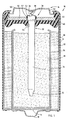
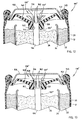
Fig. 1 is a cutaway view of an electrochemical cell having a collector and seal assembly according to a first embodiment of the present invention, shown in a sealed (non-vented) position; -
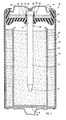
Fig. 2 is a cutaway view of the electrochemical cell ofFig. 1 with the collector and seal assembly shown in a vented position; -
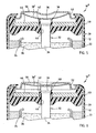
Fig. 3 is a partial cutaway view of an electrochemical cell having a collector and seal assembly according to a second embodiment of the present invention, shown in a sealed (non-vented) position; -
Fig. 4 is a partial cutaway view of the electrochemical cell ofFig. 3 with the collector and seal assembly shown in a vented position; -
Fig. 5 is a partial cutaway view of an electrochemical cell having a collector and seal assembly according to a third embodiment of the present invention, shown in a sealed (non-vented) position; -
Fig. 6 is a partial cutaway view of the electrochemical cell ofFig. 5 with the collector and seal assembly shown in a vented position; -
Fig. 7 is an elevated perspective view of the collector connector shown in the embodiment ofFig. 5 ; -
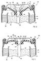
Fig. 8 is a partial cutaway view of an electrochemical cell having a collector and seal assembly according to a fourth embodiment of the present invention, shown in a sealed (non-vented) position; -
Fig. 9 is a partial cutaway view of the electrochemical cell ofFig. 8 with the collector and seal assembly shown in a vented position; -
Fig. 10 is a partial cutaway view of the electrochemical cell ofFig. 8 with the collector and seal assembly partially retracted from the vented position; -
Fig. 11 is an elevated perspective view of the annular seal member shown in the embodiment ofFig. 8 ; -
Fig. 12 is a partial cutaway view of an electrochemical cell having a collector and seal assembly according to a fifth embodiment of the present invention, shown in a sealed (non-vented) position; and -
Fig. 13 is a partial cutaway view of the electrochemical cell ofFig. 12 with the collector and seal assembly shown in a vented position. - Referring to
Fig. 1 , a cylindrical alkalineelectrochemical cell 10 is shown having a collector andseal assembly 30 according to a first embodiment of the present invention.Electrochemical cell 10 includes a cylindrical steel can 12 having a closedbottom end 14, an opentop end 16, and a cylindrical side wall extending between the bottom and top ends. The closedbottom end 14 of can 12 has a positive cover welded or otherwise attached thereto and formed of plated steel, with aprotruding nubbin 18 at its center region, which forms the positive contact terminal ofcell 10. Assembled to the opentop end 16 of steel can 12 is the collector and sealassembly 30, and an outernegative cover 50, preferably formed of plated steel, which forms the negative contact terminal ofcell 10. A metalized,plastic film label 20 is formed about the exterior surface of steel can 12, except for the ends of steel can 12.Film label 20 is formed over the peripheral edge of the positive cover and may extend partially over the peripheral edge of thenegative cover 50. - A
positive electrode 22, also referred to herein as the cathode, is formed about the interior surface of steel can 12. According to one example, thecathode 22 is formed of a mixture of manganese dioxide, graphite, potassium hydroxide solution, and additives. Aseparator 24, which is preferably formed of a non-woven fabric that prevents migration of any solid particles in the cell, is disposed about the interior surface ofcathode 22. Anegative electrode 26, also referred to herein as theanode 26, is disposed with an electrolyte inside theseparator 24 and in contact with acurrent collector 32. The electrolyte may include an alkaline electrolyte containing potassium hydroxide (KOH). According to one example, theanode 26 is formed of zinc powder, a gelling agent, and additives. The manganese dioxide and zinc employed in thecathode 22 andanode 26, respectively, are electrochemically active materials. Accordingly, thecathode 22 is configured as the cell's positive electrode, and theanode 26 is configured as the cell's negative electrode. - The
current collector 32 contacts the outernegative cover 50 which forms the negative contact terminal ofcell 10. Thecurrent collector 32 is generally configured in the shape of a nail having an elongatedcylindrical shaft 34, a truncatedconical tip 35 at the lower end, and anenlarged head 36 at the upper end. Theelongated shaft 34 is disposed in contact with theanode 26 and, in this embodiment, has a substantially uniform diameter. Thecurrent collector 32 is connected to the outernegative terminal 50 via a coiledconductive connector 38 that is compressible. The coiledconnector 38 may be welded to the bottom surface of outernegative cover 50 and/or to the upper surface ofenlarged head 36 ofcurrent collector 32, or alternately may be held in contact therewith via pressure contact.Current collector 32 andconnector 38 serve as an electrical current path to provide the negative polarity at the outernegative cover 50. - An
annular polymeric seal 40 is disposed in the open end of steel can 12 to prevent leakage of electrochemically active cell materials contained in steel can 12.Polymeric seal 40 may comprise a synthetic thermoplastic resin such as nylon. Alternate materials forseal 40 may include polypropylene, such as Noryl® Extend which is commercially available from General Electric Company, and other materials that would be recognized as suitable forseal 40. -
Seal 40 has acentral hub 42 with an inner upstandingcylindrical wall 44 defining a central opening (i.e., aperture) for receiving thecurrent collector 32.Hub 42 is generally defined as the central portion ofseal 40 containingupstanding wall 44 which is compressed against thecurrent collector 32. Theenlarged head 36 ofcurrent collector 32 is generally oversized for the hub opening, and thus theseal 40 is compressed against thecurrent collector 32 to form an interference fit engagement with the innerupstanding wall 44 defining the hub opening. Theupstanding wall 44 ofcentral hub 42 is configured to sealingly engage theenlarged head 36 ofcurrent collector 32 when in a sealed (non-vented) position. Thecentral hub 42 also has anupper edge 43 shown inFig. 1 formed over the upper peripheral surface ofenlarged head 36 to further resist upward movement ofcurrent collector 32. Aninner cover 46, which is preferably formed of a rigid metal, is provided to increase the rigidity and support the radial compression ofannular seal 40, thereby improving the sealing effectiveness. Theinner cover 46 is configured to contact an outer upstanding wall ofcentral hub 42 and an upstanding wall at the outerperipheral section 45 ofseal 40. While an oversizedcurrent collector 32 and aninner cover 46 are used to compress theseal 40 against thecurrent collector 32, other compression techniques such as compression rings may be employed to provide a sealed interference fit engagement between thecurrent collector 32 andseal 40. Theseal 40,inner cover 46, and outernegative cover 50 provide a low profile closure to theopen end 16 ofcan 12. In addition, the outernegative cover 50 also includes one ormore vent openings 52 that serve to expose the non-sealed volume ofcell 10 to the surrounding outside atmosphere.Vent openings 52 serve to vent pressure build-up released from within thecell 10 to the outside atmosphere once the collector and sealassembly 30 vents. - Together, the
current collector 32,annular seal 40, andinner cover 46 form the collector and sealassembly 30 which may be assembled together and inserted as a unit into theopen end 16 of steel can 12. The assembly of the collector and sealassembly 30 and closure of theopen end 16 ofcan 12 include disposing theannular polymeric seal 40 in theopen end 16 of thecan 12, which may have a flared opening or a bead formed radially inward on the inner wall of thecan 12, and crimping the upper end of thecan 12 inwardly and over theouter periphery 45 of theseal 40 to compress theseal 40 against theinner cover 46. It should also be appreciated that the outernegative cover 50 is electrically insulated from the steel can 12 by way of annularpolymeric seal 40. - According to the present invention, the current collector and seal
assembly 30 seals closed theopen end 16 ofcan 12, provides an electrical current path to the outernegative terminal 50, and further acts a pressure relief mechanism when exposed to an excessive pressure differential. The collector and sealassembly 30 is designed to release pressurized gases from within the sealed active volume ofcell 10 when theassembly 30 is exposed to a predetermined pressure differential. The pressure differential is the difference between the internal pressure below theseal 40 and the atmospheric pressure above theseal 40. The pressurized gas venting is generally achieved by relative axial (i.e., parallel to a longitudinal axis of the current collector 32) movement between thecurrent collector 32 and annularpolymeric seal 40. The pressurized gases released from the internalvolume exit cell 10 viaopenings 52 provided in the outernegative cover 50. - According to the first embodiment,
current collector 32 is interference fit and sealingly engaged withannular seal 40 while in the sealed (non-vented) position as shown inFig. 1 . The sealing engagement is formed between thehead 36 ofcollector 32 and the upstandingwall forming hub 42 ofseal 40. As the pressure increases within the sealed volume, which is generally below the bottom surface ofseal 40, such as may occur during an abusive condition, the internal pressure applies a force on thecurrent collector 32 which will tend to urge thecurrent collector 32 upward and out of sealing engagement withannular seal 40. When the pressure differential of the internal sealed volume, as compared to the outer atmospheric pressure, exceeds a predetermined pressure threshold, thecurrent collector 32 is forced free from the sealing engagement with thehub 42 ofseal 40 and moves to a vented position as shown inFig. 2 . The forced disengagement causes the upper foldedend 43 ofhub 42 to bend upward to allow upward movement ofcollector head 36. When this occurs, thecurrent collector 32 is forced upward relative to theentire hub 42 ofseal 40 which remains substantially fixed in place. It should be appreciated that thehub 42 ofseal 40 generally will not move upward more than a small distance compared to the movement of thecurrent collector 32, and thus is considered substantially fixed. In the vented position, apressure relief passage 48 is provided between theseal hub 42 and thecurrent collector 32 to allow for the release of pressurized gases from within the internal volume ofcell 10. In addition, when thecurrent collector 32 moves from the sealed position to the vented position, the coiledconductive connector 38 is compressed between the top surface of thecurrent collector head 36 and the bottom surface of outernegative terminal 50. When compressed, coiledconductive connector 38 may apply an opposing spring bias force downward such that when the pressure differential decreases to a reduced pressure threshold, thecurrent collector 32 may be biased downward so that thecollector head 36 sealingly engages theseal hub 42. In the event that the internal pressure increases after resealing, thecurrent collector 32 will again be forced upward to open thepressure relief passage 48 to further vent pressurized gases. - An electrochemical cell 10' is shown in
Figs. 3 and 4 having an alternatively configured current collector 32' as part of a collector and seal assembly 30'. The current collector 32' includes amain shaft 34 that extends to the uppermost end, without the enlarged head portion as discussed above. Instead, current collector 32' includes a plurality of longitudinal flutes (i.e., channels) 62 extending upward toward the uppermost end. It is preferred that the inner upstanding wall forming the hub ofseal 40 be no higher than the length of theflutes 62. The current collector 32' is positioned in the sealed position such that the plurality offlutes 62 are located belowseal 40, as shown inFig. 3 . The current collector 32' is interference fit and sealingly engaged with the inner upstanding wall forming the opening inhub 42 ofseal 40. During the venting operation, the current collector 32' is forced upward relative to theentire hub 42 ofseal 40 which remains substantially fixed in place as discussed above. When a sufficient internal pressure forces the current collector 32' upward, thelongitudinal flutes 62 provide a pressure relief passage around the inner upstanding wall forming the hub ofseal 40 as shown inFig. 4 . While a plurality offlutes 62 is shown, it should be appreciated that any one or more flutes may be employed according to this embodiment. - Referring to
Figs. 5-7 , anelectrochemical cell 10", according to a third embodiment, is shown similar tocell 10 ofFig. 1 , except having an alternatively configured conductive connector 38' for providing an electrical current path between thecurrent collector 32 and outernegative cover 50. Conductive connector 38' is shown inFig. 7 generally configured as a bowl-shaped disk made of conductive material, such as steel. With particular reference toFig. 5 , the upper outer peripheral rim engages the bottom surface of outernegative cover 50, while the bottom dome contacts the upper surface ofcurrent collector head 36. Conductive connector 38' preferably provides a downward biased force to thecurrent collector 32 so as to maintain a sealed engagement with theannular seal 40 while in the sealed (non-vented) position. When the sealed internal pressure reaches a predetermined pressure, relative to the atmospheric pressure, thecurrent collector 32 moves to a vented position, as shown inFig. 6 , during which the conductive connector 38' compresses vertically to allow formation of thepressure relief passage 48. Once the internal pressure decreases to a lower pressure, the conductive connector 38' may force thecurrent collector 32 back into sealing engagement withseal 40, as discussed above in connection with the first embodiment. - An
electrochemical cell 110 is shown inFigs. 8-10 having a collector and sealassembly 130 according to a fourth embodiment of the present invention.Electrochemical cell 110 includes asteel can 12,label 20,cathode 22,separator 24, and ananode 26, as described above in connection with the first and second embodiments. According to the fourth embodiment,electrochemical cell 110 includes collector and sealassembly 130 for sealing closed theopen end 16 ofcan 12, providing an electrical current path to an outernegative cover 150, and providing a pressure relief mechanism to vent pressurized gases. The collector and sealassembly 130 includes anannular polymeric seal 140 and acurrent collector 132. The current collector and sealassembly 130 of the fourth embodiment does not require an inner cover as used in the collector and seal assemblies of the first, second, and third embodiments described above. - The
current collector 132 includes a lowercylindrical shaft 134, anenlarged diameter step 139, a reduced diametercylindrical shaft 137, and anenlarged head 136 at the upper end. Thelower shaft 134 ofcurrent collector 132 extends into andcontacts anode 26. The reduceddiameter shaft 137 is located between theenlarged diameter step 139 andenlarged head 136, and preferably has a diameter less than the diameter of thelower shaft 134. The upper surface ofenlarged head 136 may be welded to, or in pressure contact with, outernegative cover 150. - The
annular seal 140 includes acentral hub 142 having an innerupstanding wall 144 defining a central opening for receiving thecurrent collector 132. The outerperipheral portion 145 ofseal 140 forms a sealed closure against thecan 12 and provides dielectric isolation between steel can 12 and outernegative cover 150. It should be appreciated that theopen end 16 of thecan 12,seal 140, andouter cover 150 are crimped so as to compress theseal 140 and provide a sealed closure. Thecurrent collector 132 is interference fit within the opening formed by innerupstanding wall 144 ofseal 140. The innerupstanding wall 144 ofseal 140 is compressed againstcurrent collector 132 and sealingly engages thecurrent collector 132 when in a sealed (non-vented) position as shown inFig. 8 . - Referring to
Fig. 9 , theelectrochemical cell 110 is shown with the collector and sealassembly 130 in a vented position. When the internal pressure within the sealed volume ofelectrochemical cell 110 exceeds a predetermined pressure threshold, relative to the atmospheric pressure, thecentral hub 142 ofseal 140 is forced upward due to the differential pressure applied to theseal 140. When the pressure differential exceeds the pressure threshold,hub 142 is forced over theenlarged diameter step 139 to a position abovestep 139 to provide apressure relief passage 148 betweenseal 140 andcurrent collector 132. When this occurs, theentire hub 142 is forced upward relative to thecurrent collector 132 which remains substantially fixed in place. It should be appreciated that thecurrent collector 132 may move upward a small distance, however, it is a relatively small distance compared to the movement of theentire hub 142 ofseal 140. By providing the reduceddiameter section 137, thepressure relief path 148 is provided without allowing resealing betweenreduced diameter section 137 andseal 140.Outer cover 150 includes one ormore vent openings 152 to vent pressure build-up released from withincell 110 to the outside atmosphere. - Once the pressure differential has decreased to a lower pressure, the
hub 142 ofseal 140 may slide downwardly (retract) back into sealing engagement on the upper side of theenlarged diameter step 139 as shown inFig. 10 .Central hub 142 ofseal 140 has a shaped surface indentation (bevel) 141 provided in the lower section ofupstanding wall 144 which substantially conforms to the shape of the upper surface ofenlarged diameter step 139. Upon retracting downward, theseal 140 may again sealingly engagecurrent collector 132 to prevent further discharge of gases and other material. It should be appreciated that upon the pressure differential increasing, additional venting of pressurized gases may occur. - With particular reference to
Fig. 11 , theannular polymeric seal 140 is shown having a plurality ofchannels 160 formed in the upper surface. It should be appreciated that by employing one or more standoff members, such aschannels 160, in the upper surface ofseal 140, thechannels 160 provide a vent path to prevent resealing ofseal 140 withcurrent collector 132 when in the vent position. It should also be appreciated that as an alternative two channels, other standoff members, such as ribs or other surface protrusions, may be provided either on the upper surface ofseal 140 or on the surface ofcurrent collector 130 to prevent resealing during the venting operation. Examples of anti-resealing assemblies are disclosed inU.S. Application Serial No. 09/300,413, filed April 27, 1999 US-A-6,270,919 ). - Referring to
Figs. 12 and 13 , an electrochemical cell 110' is illustrated having a collector and seal assembly 130' according to a fifth embodiment of the present invention. Theelectrochemical cell 110 likewise includes asteel can 12,label 20,cathode 22,separator 24,anode 26, and other components as discussed above. The collector and seal assembly 130' of the fifth embodiment includes a current collector 132' having alower shaft 134, anenlarged diameter step 139, and a plurality of longitudinal flutes (i.e., channels) 162 extending from theenlarged diameter step 139 upward toward theenlarged head 136. The current collector 132' is likewise connected to the outernegative cover 150. The plurality offlutes 162 providepressure relief passages 148 for releasing pressurized gases from the internal volume of the cell 110' in a controlled operation. In the non-vented position, shown inFig. 12 , thehub 142 ofseal 140 provides sealing engagement betweenupstanding walls 144 and each ofshaft 134 and step 139 of current collector 132'. Theshaft 134 of current collector 132' is interference fit within the opening formed by the inner walls ofhub 142 ofseal 140. When the internal pressure within the sealed volume of cell 110' increases beyond a predetermined pressure threshold, thecentral hub 142 slides upward along current collector 132' until one or morepressure relief passages 148 are provided throughflutes 162 to release the high pressure gases from within the sealed volume, as shown inFig. 13 . It should be appreciated that the current collector 132' remains substantially fixed, relative to the movement of theentire hub 142 ofseal 140, as discussed above. By providing a plurality offlutes 162 to serve as the pressure relief passages, a controlled low pressure release of gases may be achieved according to this embodiment. - The
seal member 140 is made of a polymeric material, such as Noryl® Extend which is commercially available from General Electric Company of Selkirk, New York. Noryl® Extend is a polypropylene matrix having polyethylene therein, which acts as a polymer stiffener. Noryl® Extend provides low moisture absorption, will not hydrolyze in the presence of KOH, and has very low stress relaxation. These characteristics allow the seal design of the present invention to be feasible, whereas use of a material such as nylon for theseal 140 of the present invention would require the use of a support. This is due to nylon cracking in the presence of KOH coupled with stress on the seal (in the hoop direction) due to the nail vent design. - It should be appreciated that, while Noryl® Extend is a preferred material for
seal 140 that resists cracking, particularly in the central hub, other seal materials could be used. For example, theseal members Seal members seal members - While the various embodiments described herein provide a pressure relief passage achieved by relative axial movement between a collector and a seal, it should be appreciated that other vent passages may be provided. For example, the relative movement between the seal and collector may be designed to cause the seal hub to split open, thereby further creating a pressure relief passage through the split opening.
- Accordingly, the present invention advantageously provides collector and seal assemblies for sealing the open end of an electrochemical cell and realizing a controlled venting operation to vent high pressure gases, particularly when the cell is subjected to an abusive condition. The collector and seal assemblies of the present invention each offer a simplified seal design in a low profile assembly which results in greater volume available for active battery components. The seals of the present invention are easy to mold, since no conventional thin sections are required for the vent diaphragm. In addition, a wide range of vent pressures is achievable by adjusting the nail step diameter in its relation to the seal hub inside diameter, seal hub outside diameter, and nail diameter below the enlarged diameter step. The venting rate can easily be adjusted with the collector and seal assemblies of the present application. Generally, the pressurized gases in the cell will escape faster if the diameter difference between the vent region of the nail and seal is made greater, and if the vent channel cross section area on top of the seal is increased. Likewise, the seal can be designed to vent slower to create less release spray if the diameter clearance is decreased or the vent channel is decreased. By providing the seal such that it can flex back to a non-vent position, reduced or prevented leakage of electrolyte after the seal has vented can be achieved. Further, it should be appreciated that the collector and seal assemblies of the present invention employ fewer parts and less volume than conventional seal assemblies.
- While the collector and seal assemblies have been described herein in connection with a cylindrical bobbin-type electrochemical cell, it should be appreciated that the invention concepts are likewise applicable to various other cell configurations including jelly roll cells, prismatic cells, cells employing multiple anodes and multiple current collectors and cells in which the cans and current collectors are electrically connected to the negative and positive electrodes, respectively. Additionally, it should also be appreciated that the collector and seal assemblies described herein may be sealed closed against the steel can using various different can closures.
Claims (17)
- An electrochemical cell (10) comprising: a container (12) having a bottom end (14) and an open top end (16); a positive electrode (22) disposed in the container (12); a negative electrode (26) disposed in the container (12); and a collector and seal assembly (30) for sealing the open end (16) of the electrochemical cell container (12), the collector and seal assembly (30) comprising:a seal member adapted to be disposed in the open end (16) of the container (12) to provide a sealed closure to the open end (16) of the container (12), the seal member (40) having an opening therein, which is defined by a central hub (42) containing an upstanding wall (44), wherein the central hub (42) sealingly engages the shaft (34) of the current collector (32) in the sealed position, and one of the hub (42) and the current collector (32) is axially movable relative to the other of the hub (42) and the current collector (32) to move to a vent position; anda current collector (32) having a shaft (34) extending through the opening in the seal member (40), wherein the current collector (32) is interference fit within the opening such that the seal member upstanding wall (44) sealingly engages the shaft (34) of the current collector (32) when in a sealed position, and at least one of the seal member (40) and the current collector (32) is axially movable, relative to the other of the seal member (40) and the current collector (32), to a vent position upon exposure to a predetermined pressure so as to provide a pressure relief passage (48) between the seal member upstanding wall (44) and the current collector (32) for venting pressurized gases.
- An electrochemical cell (10) according to claim 1 further comprising an outer cover (50).
- An electrochemical cell (10) according to claim 1 or claim 2, the cell further comprising an inner cover (46), wherein the inner cover (46) is electrically insulated from the outer cover (50).
- An electrochemical cell (10) according to any of claims 1 to 3, wherein the current collector (32) is axially movable within the opening of the seal member (40) from the sealed position to the vent position upon experiencing a predetermined pressure within the cell (10) so as to provide a pressure relief passage (48) to vent pressurized gases.
- An electrochemical cell (10) according to any of claims 2 to 3, the cell further comprising a conductive connector (38) electrically coupling the outer cover (50) and the current collector (32), wherein the conductive connector (38) biases the current collector (32) towards the seal member (40).
- An electrochemical cell (10) according to claim 5, wherein the conductive connector (38) comprises a compressible spring.
- An electrochemical cell (10) according to claim 6, wherein the spring comprises a coil spring.
- An electrochemical cell (10) according to claim 5, wherein the conductive connector (38) comprises a bowl-shaped disk.
- An electrochemical cell (10) according to any of claims 1 to 8, wherein the current collector (32) and seal member (40) are capable of sealingly re-engaging each other following initial pressure venting.
- An electrochemical cell (10) according to any of claims 1 to 8, wherein the seal member (40) is axially movable along the shaft (34) of the current collector (32) from the sealed position to the vent position upon experiencing a predetermined pressure within the cell (10) so as to provide a pressure relief passage (48) to vent pressurized gases.
- An electrochemical cell (10) according to claim 10, wherein the current collector (32) includes a shaft (34) having a first diameter, sealingly engaging the seal member (40) in the sealed position, and a second diameter, that has a diameter less than the first diameter, wherein the seal member (40) is movable along the shaft (34) from the first diameter towards the second diameter to provide the pressure relief passage (48) when the seal member (40) is in the vent position.
- An electrochemical cell (10) according to claim 11, wherein the current collector (32) includes an enlarged diameter step provided on the shaft (34), wherein the seal member (40) is retained by the enlarged diameter step in the sealed position, and wherein a central hub (42) of the seal member (40) is moveable along the shaft (34), over the enlarged diameter step, to the vent position.
- An electrochemical cell (10) according to any of claims 10 to 12, wherein the current collector (32) has one or more flutes (62) formed therein for providing the pressure relief passage (48) when in the vent position.
- An electrochemical cell (10) according to any of claims 10 to 13, wherein the seal member (40) includes a vent path (52) provided on the top surface of the seal member (40) to prevent resealing of the current collector (32) and seal member (40) when in the vent position.
- An electrochemical cell (10) according to any of claims 1 to 14 further comprising an alkaline electrolyte.
- An electrochemical cell (10) according to any of claims 1 to 15, wherein the seal member (40) comprises polymeric material.
- An electrochemical cell (10) according to claim 16 wherein the polymeric material comprises polypropylene.
Applications Claiming Priority (3)
| Application Number | Priority Date | Filing Date | Title |
|---|---|---|---|
| US10/034,687 US6855454B2 (en) | 2001-12-20 | 2001-12-20 | Electrochemical cell having venting current collector and seal assembly |
| US34687 | 2001-12-20 | ||
| PCT/US2002/039744 WO2003054983A2 (en) | 2001-12-20 | 2002-12-12 | Electrochemical cell having venting current collector and seal assembly |
Publications (2)
| Publication Number | Publication Date |
|---|---|
| EP1456894A2 EP1456894A2 (en) | 2004-09-15 |
| EP1456894B1 true EP1456894B1 (en) | 2012-08-08 |
Family
ID=21877969
Family Applications (1)
| Application Number | Title | Priority Date | Filing Date |
|---|---|---|---|
| EP02797287A Expired - Lifetime EP1456894B1 (en) | 2001-12-20 | 2002-12-17 | Electrochemical cell having venting current collector and seal assembly |
Country Status (6)
| Country | Link |
|---|---|
| US (2) | US6855454B2 (en) |
| EP (1) | EP1456894B1 (en) |
| JP (1) | JP4421896B2 (en) |
| CN (1) | CN100336243C (en) |
| AU (1) | AU2002361648A1 (en) |
| WO (1) | WO2003054983A2 (en) |
Families Citing this family (32)
| Publication number | Priority date | Publication date | Assignee | Title |
|---|---|---|---|---|
| US6855454B2 (en) * | 2001-12-20 | 2005-02-15 | Eveready Battery Company, Inc. | Electrochemical cell having venting current collector and seal assembly |
| USD490773S1 (en) | 2003-06-11 | 2004-06-01 | Matsushita Electric Industrial Co., Ltd. | Current collector for a battery |
| JP4416443B2 (en) * | 2003-06-26 | 2010-02-17 | パナソニック株式会社 | Battery pack and manufacturing method thereof |
| US20050048366A1 (en) * | 2003-08-27 | 2005-03-03 | Bowden William L. | Cathode material and method of manufacturing |
| TW200529484A (en) * | 2003-11-13 | 2005-09-01 | Rovcal Inc | Pressure dissipation assembly for electrochemical cell |
| KR100560494B1 (en) * | 2003-11-29 | 2006-03-13 | 삼성에스디아이 주식회사 | Cap Assembly and Secondary Battery Using the Same |
| USD522452S1 (en) | 2004-09-13 | 2006-06-06 | Matsushita Electric Industrial Co., Ltd. | Insulating plate for a battery |
| FR2894381B1 (en) * | 2005-12-05 | 2008-02-15 | Batscap Sa | ELECTRIC ENERGY STORAGE SYSTEM |
| US20080026286A1 (en) * | 2006-07-31 | 2008-01-31 | Eveready Battery Company, Inc. | Nail-type current collector with non-conductive core and surface metallization for electrochemical cell |
| EP2149169B8 (en) * | 2007-05-08 | 2017-10-18 | BS&B Innovations Limited | Pressure response membrane |
| CN101689621B (en) * | 2007-06-29 | 2013-03-27 | 永备电池有限公司 | Vapor Permeation Resistance Sealing Elements for Nonaqueous Electrochemical Cells |
| JP2011216217A (en) * | 2010-03-31 | 2011-10-27 | Panasonic Corp | Alkaline dry battery |
| JP5514632B2 (en) * | 2010-05-27 | 2014-06-04 | Fdkエナジー株式会社 | Cylindrical battery sealing gasket and cylindrical battery |
| GB201118842D0 (en) * | 2011-11-01 | 2011-12-14 | Euro Celtique Sa | Dispenser cap arrangement |
| CN102522518B (en) * | 2011-12-02 | 2013-09-25 | 苏州冠硕新能源有限公司 | Battery connecting assembly, producing method thereof and lithium battery |
| DE102012222836A1 (en) * | 2012-12-12 | 2014-06-12 | Robert Bosch Gmbh | Housing for a gas-tight accumulator |
| DE102015111572A1 (en) * | 2015-07-16 | 2017-01-19 | Schuler Pressen Gmbh | Battery cell housing and method for its manufacture |
| WO2017100847A1 (en) * | 2015-12-14 | 2017-06-22 | Aquahydrex Pty Ltd | Electrochemical cell and components thereof capable of operating at high current density |
| DE102016004648A1 (en) * | 2016-04-16 | 2017-10-19 | Daimler Ag | Pressure relief device for a battery case, battery case with the pressure relief device, battery and method for depressurizing a battery |
| WO2018126439A1 (en) * | 2017-01-06 | 2018-07-12 | 宁德时代新能源科技股份有限公司 | Power battery cover structure, power battery, and battery module |
| KR20250116186A (en) | 2017-03-30 | 2025-07-31 | 도날드슨 컴파니, 인코포레이티드 | Vent with relief valve |
| CN111727515B (en) * | 2018-02-20 | 2022-05-31 | 松下知识产权经营株式会社 | Cylindrical battery |
| JP7049865B2 (en) * | 2018-03-06 | 2022-04-07 | Fdk株式会社 | Alkaline batteries and methods for manufacturing alkaline batteries |
| DE102018210841A1 (en) * | 2018-07-02 | 2020-01-02 | Volkswagen Aktiengesellschaft | Bushing element and system from a separation layer and a bushing element |
| DE102019100094A1 (en) * | 2019-01-04 | 2020-07-09 | Mann+Hummel Gmbh | Degassing unit and electronics housing, in particular battery housing |
| CN110165120B (en) * | 2019-05-15 | 2022-04-08 | 广东微电新能源有限公司 | Battery structure with deformation pressure relief function |
| US11101597B1 (en) | 2020-05-06 | 2021-08-24 | Lear Corporation | Vented electrical connector |
| AU2021273919A1 (en) | 2020-05-22 | 2022-10-06 | Duracell U.S. Operations, Inc. | Seal assembly for a battery cell |
| CN113675510B (en) * | 2021-08-17 | 2023-01-24 | 厦门海辰储能科技股份有限公司 | The end connection structure of the battery cell, the battery cell, and the power battery |
| EP4409655A2 (en) * | 2021-09-29 | 2024-08-07 | Medtronic, Inc. | Current collector with vent channels |
| WO2025182677A1 (en) * | 2024-02-29 | 2025-09-04 | パナソニックIpマネジメント株式会社 | Sealed battery |
| US20250293384A1 (en) * | 2024-03-13 | 2025-09-18 | GM Global Technology Operations LLC | Cell integrated vent gas diverter with particle trap |
Citations (2)
| Publication number | Priority date | Publication date | Assignee | Title |
|---|---|---|---|---|
| US3923548A (en) * | 1972-05-24 | 1975-12-02 | Varta Batterie | Elastic gas valve for galvanic cells |
| EP0327366A2 (en) * | 1988-02-04 | 1989-08-09 | British Ever Ready Limited | Cell and method of assembling same |
Family Cites Families (37)
| Publication number | Priority date | Publication date | Assignee | Title |
|---|---|---|---|---|
| US454598A (en) | 1891-06-23 | Philip hathaway | ||
| US1650319A (en) | 1924-05-07 | 1927-11-22 | Nat Carbon Co Inc | Seal for galvanic cells |
| US2060799A (en) | 1932-11-30 | 1936-11-17 | Nat Carbon Co Inc | Closure for dry cells |
| US3062910A (en) | 1961-03-09 | 1962-11-06 | Gould National Batteries Inc | Sealing and pressure relief device for galvanic cells |
| GB1200173A (en) | 1966-10-10 | 1970-07-29 | Alkaline Batteries Ltd | Improvements relating to venting devices for electric storage cells |
| US3663301A (en) | 1970-04-09 | 1972-05-16 | Mallory & Co Inc P R | Leak-proof primary cell |
| CA962736A (en) | 1970-08-07 | 1975-02-11 | Sumio Uchida | Cell jacket for metal/air or metal/oxygen cells |
| US3967977A (en) | 1975-03-28 | 1976-07-06 | Union Carbide Corporation | Closure for galvanic dry cells |
| US3980500A (en) | 1975-05-30 | 1976-09-14 | Gould Inc. | Resealable vent for plastic battery case |
| JPS541008A (en) | 1977-06-03 | 1979-01-06 | Efu Tei Giken Kk | Vtr system |
| US4227701A (en) * | 1979-01-02 | 1980-10-14 | Fuji Electrochemical Co., Ltd. | Rupturable sealing structure of cell |
| US4366213A (en) | 1981-06-16 | 1982-12-28 | Tamminen Pentti J | Battery and contact combination |
| JPS5933751A (en) | 1982-08-17 | 1984-02-23 | Hitachi Maxell Ltd | Cylindrical alkaline battery |
| US4431716A (en) | 1983-02-11 | 1984-02-14 | Honeywell Inc. | Heat activated vent |
| US4567118A (en) | 1983-07-11 | 1986-01-28 | Duracell Inc. | Cell vent |
| US4672010A (en) | 1986-07-18 | 1987-06-09 | Eveready Battery Company | Terminal pin-collector plate assembly for hermetically sealed cells |
| GB8815181D0 (en) | 1988-06-25 | 1988-08-03 | Tucke Fasteners Ltd | Electrical storage cell |
| US5080985A (en) * | 1989-12-07 | 1992-01-14 | Duracell Inc. | High pressure seal for alkaline cells |
| US5188909A (en) * | 1991-09-12 | 1993-02-23 | Eveready Battery Co., Inc. | Electrochemical cell with circuit disconnect device |
| US5227261A (en) | 1991-10-15 | 1993-07-13 | Eveready Battery Company, Inc. | Cylindrical electrochemical cells with a diaphragm seal |
| JP2993238B2 (en) | 1991-11-22 | 1999-12-20 | 富士電気化学株式会社 | Manufacturing method of cylindrical alkaline battery |
| JPH05182648A (en) | 1991-12-28 | 1993-07-23 | Sony Corp | Alkaline battery |
| JPH05325929A (en) | 1992-05-20 | 1993-12-10 | Hitachi Maxell Ltd | Alkaline storage battery |
| US5422201A (en) | 1993-08-04 | 1995-06-06 | Eveready Battery Company, Inc. | Current collector assembly for an electrochemical cell |
| US5532075A (en) | 1994-07-06 | 1996-07-02 | Alexander Manufacturing Corporation | Small battery cell |
| JP3612629B2 (en) | 1995-03-07 | 2005-01-19 | 株式会社京浜理化工業 | Non-aqueous battery |
| JP3573853B2 (en) | 1995-11-30 | 2004-10-06 | 三洋電機株式会社 | Sealed battery |
| JPH09245758A (en) | 1996-03-08 | 1997-09-19 | Sony Corp | AA alkaline battery |
| US6022635A (en) | 1997-09-24 | 2000-02-08 | Eveready Battery Company, Inc. | Electrochemical cell having a moisture barrier |
| US6127062A (en) * | 1998-03-24 | 2000-10-03 | Duracell Inc | End cap seal assembly for an electrochemical cell |
| JP3576384B2 (en) | 1998-06-12 | 2004-10-13 | 松下電器産業株式会社 | Alkaline battery |
| JP3432746B2 (en) | 1998-06-18 | 2003-08-04 | 株式会社三ツ星電器製作所 | Ceiling-mounted lighting fixture mounting device |
| JP2000011981A (en) | 1998-06-25 | 2000-01-14 | Shin Kobe Electric Mach Co Ltd | Non-aqueous electrolyte secondary battery |
| US6300004B1 (en) | 1998-08-21 | 2001-10-09 | Eveready Battery Company, Inc. | Battery constructions having reduced collector assembly volume |
| JP3789659B2 (en) | 1998-10-30 | 2006-06-28 | 三洋電機株式会社 | Non-aqueous electrolyte battery |
| US6312850B1 (en) | 1999-09-14 | 2001-11-06 | Eveready Battery Company, Inc. | Current collector and seal assembly for electrochemical cell |
| US6855454B2 (en) * | 2001-12-20 | 2005-02-15 | Eveready Battery Company, Inc. | Electrochemical cell having venting current collector and seal assembly |
-
2001
- 2001-12-20 US US10/034,687 patent/US6855454B2/en not_active Expired - Lifetime
-
2002
- 2002-12-12 WO PCT/US2002/039744 patent/WO2003054983A2/en not_active Ceased
- 2002-12-12 CN CNB028258525A patent/CN100336243C/en not_active Expired - Fee Related
- 2002-12-12 JP JP2003555601A patent/JP4421896B2/en not_active Expired - Fee Related
- 2002-12-12 AU AU2002361648A patent/AU2002361648A1/en not_active Abandoned
- 2002-12-17 EP EP02797287A patent/EP1456894B1/en not_active Expired - Lifetime
-
2004
- 2004-10-21 US US10/970,323 patent/US7122270B2/en not_active Expired - Lifetime
Patent Citations (2)
| Publication number | Priority date | Publication date | Assignee | Title |
|---|---|---|---|---|
| US3923548A (en) * | 1972-05-24 | 1975-12-02 | Varta Batterie | Elastic gas valve for galvanic cells |
| EP0327366A2 (en) * | 1988-02-04 | 1989-08-09 | British Ever Ready Limited | Cell and method of assembling same |
Also Published As
| Publication number | Publication date |
|---|---|
| HK1069483A1 (en) | 2005-05-20 |
| WO2003054983A8 (en) | 2004-07-08 |
| WO2003054983A2 (en) | 2003-07-03 |
| CN1636285A (en) | 2005-07-06 |
| EP1456894A2 (en) | 2004-09-15 |
| US20030118892A1 (en) | 2003-06-26 |
| AU2002361648A1 (en) | 2003-07-09 |
| JP4421896B2 (en) | 2010-02-24 |
| AU2002361648A8 (en) | 2003-07-09 |
| US6855454B2 (en) | 2005-02-15 |
| US7122270B2 (en) | 2006-10-17 |
| CN100336243C (en) | 2007-09-05 |
| US20050053832A1 (en) | 2005-03-10 |
| WO2003054983A3 (en) | 2003-11-13 |
| JP2005514730A (en) | 2005-05-19 |
Similar Documents
| Publication | Publication Date | Title |
|---|---|---|
| EP1456894B1 (en) | Electrochemical cell having venting current collector and seal assembly | |
| JP2005514730A6 (en) | Electrochemical cell with vent current collector and seal assembly | |
| US7704632B2 (en) | Electrochemical cell having a vent assembly with a rupturable seal member | |
| US6620543B2 (en) | Electrochemical cell having can vent and cover terminal | |
| EP1192678B1 (en) | Electrochemical cell having low profile seal assembly with anti-resealing vent | |
| WO2001020693A1 (en) | Current collector and seal assembly for electrochemical cell | |
| US6495284B2 (en) | End seal assembly for an alkaline cell | |
| US6206938B1 (en) | Snap-through gasket for galvanic cells | |
| WO2008041200A1 (en) | End cap seal assembly for an electrochemical cell | |
| WO2000046864A2 (en) | Low profile ventable seal for an electrochemical cell | |
| EP1476910B1 (en) | Seal for an electrochemical cell | |
| HK1069483B (en) | Electrochemical cell having venting current collector and seal assembly |
Legal Events
| Date | Code | Title | Description |
|---|---|---|---|
| PUAI | Public reference made under article 153(3) epc to a published international application that has entered the european phase |
Free format text: ORIGINAL CODE: 0009012 |
|
| 17P | Request for examination filed |
Effective date: 20040616 |
|
| AK | Designated contracting states |
Kind code of ref document: A2 Designated state(s): AT BE BG CH CY CZ DE DK EE ES FI FR GB GR IE IT LI LU MC NL PT SE SI SK TR |
|
| AX | Request for extension of the european patent |
Extension state: AL LT LV MK RO |
|
| REG | Reference to a national code |
Ref country code: HK Ref legal event code: DE Ref document number: 1069483 Country of ref document: HK |
|
| 17Q | First examination report despatched |
Effective date: 20060207 |
|
| GRAP | Despatch of communication of intention to grant a patent |
Free format text: ORIGINAL CODE: EPIDOSNIGR1 |
|
| RIC1 | Information provided on ipc code assigned before grant |
Ipc: H01M 2/12 20060101AFI20120126BHEP Ipc: H01M 2/04 20060101ALI20120126BHEP |
|
| GRAS | Grant fee paid |
Free format text: ORIGINAL CODE: EPIDOSNIGR3 |
|
| GRAA | (expected) grant |
Free format text: ORIGINAL CODE: 0009210 |
|
| AK | Designated contracting states |
Kind code of ref document: B1 Designated state(s): AT BE BG CH CY CZ DE DK EE ES FI FR GB GR IE IT LI LU MC NL PT SE SI SK TR |
|
| REG | Reference to a national code |
Ref country code: GB Ref legal event code: FG4D Ref country code: DE Ref legal event code: R081 Ref document number: 60243488 Country of ref document: DE Owner name: ENERGIZER BRANDS, LLC (N.D.GES.D. STAATES DELA, US Free format text: FORMER OWNER: EVEREADY BATTERY CO., INC., WESTLAKE, OHIO, US |
|
| REG | Reference to a national code |
Ref country code: CH Ref legal event code: EP Ref country code: AT Ref legal event code: REF Ref document number: 570163 Country of ref document: AT Kind code of ref document: T Effective date: 20120815 |
|
| REG | Reference to a national code |
Ref country code: IE Ref legal event code: FG4D |
|
| REG | Reference to a national code |
Ref country code: DE Ref legal event code: R096 Ref document number: 60243488 Country of ref document: DE Effective date: 20121011 |
|
| REG | Reference to a national code |
Ref country code: NL Ref legal event code: VDEP Effective date: 20120808 |
|
| REG | Reference to a national code |
Ref country code: AT Ref legal event code: MK05 Ref document number: 570163 Country of ref document: AT Kind code of ref document: T Effective date: 20120808 |
|
| PG25 | Lapsed in a contracting state [announced via postgrant information from national office to epo] |
Ref country code: CY Free format text: LAPSE BECAUSE OF FAILURE TO SUBMIT A TRANSLATION OF THE DESCRIPTION OR TO PAY THE FEE WITHIN THE PRESCRIBED TIME-LIMIT Effective date: 20120808 Ref country code: FI Free format text: LAPSE BECAUSE OF FAILURE TO SUBMIT A TRANSLATION OF THE DESCRIPTION OR TO PAY THE FEE WITHIN THE PRESCRIBED TIME-LIMIT Effective date: 20120808 Ref country code: AT Free format text: LAPSE BECAUSE OF FAILURE TO SUBMIT A TRANSLATION OF THE DESCRIPTION OR TO PAY THE FEE WITHIN THE PRESCRIBED TIME-LIMIT Effective date: 20120808 |
|
| PG25 | Lapsed in a contracting state [announced via postgrant information from national office to epo] |
Ref country code: PT Free format text: LAPSE BECAUSE OF FAILURE TO SUBMIT A TRANSLATION OF THE DESCRIPTION OR TO PAY THE FEE WITHIN THE PRESCRIBED TIME-LIMIT Effective date: 20121210 Ref country code: SI Free format text: LAPSE BECAUSE OF FAILURE TO SUBMIT A TRANSLATION OF THE DESCRIPTION OR TO PAY THE FEE WITHIN THE PRESCRIBED TIME-LIMIT Effective date: 20120808 Ref country code: SE Free format text: LAPSE BECAUSE OF FAILURE TO SUBMIT A TRANSLATION OF THE DESCRIPTION OR TO PAY THE FEE WITHIN THE PRESCRIBED TIME-LIMIT Effective date: 20120808 Ref country code: GR Free format text: LAPSE BECAUSE OF FAILURE TO SUBMIT A TRANSLATION OF THE DESCRIPTION OR TO PAY THE FEE WITHIN THE PRESCRIBED TIME-LIMIT Effective date: 20121109 |
|
| REG | Reference to a national code |
Ref country code: HK Ref legal event code: GR Ref document number: 1069483 Country of ref document: HK |
|
| PG25 | Lapsed in a contracting state [announced via postgrant information from national office to epo] |
Ref country code: NL Free format text: LAPSE BECAUSE OF FAILURE TO SUBMIT A TRANSLATION OF THE DESCRIPTION OR TO PAY THE FEE WITHIN THE PRESCRIBED TIME-LIMIT Effective date: 20120808 |
|
| PG25 | Lapsed in a contracting state [announced via postgrant information from national office to epo] |
Ref country code: ES Free format text: LAPSE BECAUSE OF FAILURE TO SUBMIT A TRANSLATION OF THE DESCRIPTION OR TO PAY THE FEE WITHIN THE PRESCRIBED TIME-LIMIT Effective date: 20121119 Ref country code: CZ Free format text: LAPSE BECAUSE OF FAILURE TO SUBMIT A TRANSLATION OF THE DESCRIPTION OR TO PAY THE FEE WITHIN THE PRESCRIBED TIME-LIMIT Effective date: 20120808 Ref country code: EE Free format text: LAPSE BECAUSE OF FAILURE TO SUBMIT A TRANSLATION OF THE DESCRIPTION OR TO PAY THE FEE WITHIN THE PRESCRIBED TIME-LIMIT Effective date: 20120808 Ref country code: DK Free format text: LAPSE BECAUSE OF FAILURE TO SUBMIT A TRANSLATION OF THE DESCRIPTION OR TO PAY THE FEE WITHIN THE PRESCRIBED TIME-LIMIT Effective date: 20120808 |
|
| PG25 | Lapsed in a contracting state [announced via postgrant information from national office to epo] |
Ref country code: SK Free format text: LAPSE BECAUSE OF FAILURE TO SUBMIT A TRANSLATION OF THE DESCRIPTION OR TO PAY THE FEE WITHIN THE PRESCRIBED TIME-LIMIT Effective date: 20120808 Ref country code: IT Free format text: LAPSE BECAUSE OF FAILURE TO SUBMIT A TRANSLATION OF THE DESCRIPTION OR TO PAY THE FEE WITHIN THE PRESCRIBED TIME-LIMIT Effective date: 20120808 |
|
| PLBE | No opposition filed within time limit |
Free format text: ORIGINAL CODE: 0009261 |
|
| STAA | Information on the status of an ep patent application or granted ep patent |
Free format text: STATUS: NO OPPOSITION FILED WITHIN TIME LIMIT |
|
| 26N | No opposition filed |
Effective date: 20130510 |
|
| PG25 | Lapsed in a contracting state [announced via postgrant information from national office to epo] |
Ref country code: BG Free format text: LAPSE BECAUSE OF FAILURE TO SUBMIT A TRANSLATION OF THE DESCRIPTION OR TO PAY THE FEE WITHIN THE PRESCRIBED TIME-LIMIT Effective date: 20121108 Ref country code: MC Free format text: LAPSE BECAUSE OF NON-PAYMENT OF DUE FEES Effective date: 20121231 |
|
| REG | Reference to a national code |
Ref country code: CH Ref legal event code: PL |
|
| REG | Reference to a national code |
Ref country code: DE Ref legal event code: R097 Ref document number: 60243488 Country of ref document: DE Effective date: 20130510 |
|
| REG | Reference to a national code |
Ref country code: IE Ref legal event code: MM4A |
|
| REG | Reference to a national code |
Ref country code: FR Ref legal event code: ST Effective date: 20130830 |
|
| PG25 | Lapsed in a contracting state [announced via postgrant information from national office to epo] |
Ref country code: LI Free format text: LAPSE BECAUSE OF NON-PAYMENT OF DUE FEES Effective date: 20121231 Ref country code: CH Free format text: LAPSE BECAUSE OF NON-PAYMENT OF DUE FEES Effective date: 20121231 Ref country code: IE Free format text: LAPSE BECAUSE OF NON-PAYMENT OF DUE FEES Effective date: 20121217 |
|
| PG25 | Lapsed in a contracting state [announced via postgrant information from national office to epo] |
Ref country code: FR Free format text: LAPSE BECAUSE OF NON-PAYMENT OF DUE FEES Effective date: 20130102 |
|
| PG25 | Lapsed in a contracting state [announced via postgrant information from national office to epo] |
Ref country code: TR Free format text: LAPSE BECAUSE OF FAILURE TO SUBMIT A TRANSLATION OF THE DESCRIPTION OR TO PAY THE FEE WITHIN THE PRESCRIBED TIME-LIMIT Effective date: 20120808 |
|
| PG25 | Lapsed in a contracting state [announced via postgrant information from national office to epo] |
Ref country code: LU Free format text: LAPSE BECAUSE OF NON-PAYMENT OF DUE FEES Effective date: 20121217 |
|
| REG | Reference to a national code |
Ref country code: DE Ref legal event code: R082 Ref document number: 60243488 Country of ref document: DE Representative=s name: DOMPATENT VON KREISLER SELTING WERNER - PARTNE, DE Ref country code: DE Ref legal event code: R082 Ref document number: 60243488 Country of ref document: DE Representative=s name: VON KREISLER SELTING WERNER - PARTNERSCHAFT VO, DE Ref country code: DE Ref legal event code: R081 Ref document number: 60243488 Country of ref document: DE Owner name: ENERGIZER BRANDS, LLC (N.D.GES.D. STAATES DELA, US Free format text: FORMER OWNER: EVEREADY BATTERY CO., INC., WESTLAKE, OHIO, US |
|
| REG | Reference to a national code |
Ref country code: GB Ref legal event code: 732E Free format text: REGISTERED BETWEEN 20161013 AND 20161019 |
|
| PGFP | Annual fee paid to national office [announced via postgrant information from national office to epo] |
Ref country code: GB Payment date: 20171206 Year of fee payment: 16 |
|
| PGFP | Annual fee paid to national office [announced via postgrant information from national office to epo] |
Ref country code: DE Payment date: 20181204 Year of fee payment: 17 |
|
| PGFP | Annual fee paid to national office [announced via postgrant information from national office to epo] |
Ref country code: BE Payment date: 20181015 Year of fee payment: 17 |
|
| GBPC | Gb: european patent ceased through non-payment of renewal fee |
Effective date: 20181217 |
|
| PG25 | Lapsed in a contracting state [announced via postgrant information from national office to epo] |
Ref country code: GB Free format text: LAPSE BECAUSE OF NON-PAYMENT OF DUE FEES Effective date: 20181217 |
|
| REG | Reference to a national code |
Ref country code: DE Ref legal event code: R119 Ref document number: 60243488 Country of ref document: DE |
|
| REG | Reference to a national code |
Ref country code: BE Ref legal event code: MM Effective date: 20191231 |
|
| PG25 | Lapsed in a contracting state [announced via postgrant information from national office to epo] |
Ref country code: DE Free format text: LAPSE BECAUSE OF NON-PAYMENT OF DUE FEES Effective date: 20200701 |
|
| PG25 | Lapsed in a contracting state [announced via postgrant information from national office to epo] |
Ref country code: BE Free format text: LAPSE BECAUSE OF NON-PAYMENT OF DUE FEES Effective date: 20191231 |