EP1455541A2 - 3D display unit - Google Patents
3D display unit Download PDFInfo
- Publication number
- EP1455541A2 EP1455541A2 EP04250036A EP04250036A EP1455541A2 EP 1455541 A2 EP1455541 A2 EP 1455541A2 EP 04250036 A EP04250036 A EP 04250036A EP 04250036 A EP04250036 A EP 04250036A EP 1455541 A2 EP1455541 A2 EP 1455541A2
- Authority
- EP
- European Patent Office
- Prior art keywords
- display devices
- display
- disposed
- image
- observer
- Prior art date
- Legal status (The legal status is an assumption and is not a legal conclusion. Google has not performed a legal analysis and makes no representation as to the accuracy of the status listed.)
- Withdrawn
Links
Images

Classifications
-
- H—ELECTRICITY
- H04—ELECTRIC COMMUNICATION TECHNIQUE
- H04N—PICTORIAL COMMUNICATION, e.g. TELEVISION
- H04N13/00—Stereoscopic video systems; Multi-view video systems; Details thereof
- H04N13/30—Image reproducers
- H04N13/388—Volumetric displays, i.e. systems where the image is built up from picture elements distributed through a volume
- H04N13/395—Volumetric displays, i.e. systems where the image is built up from picture elements distributed through a volume with depth sampling, i.e. the volume being constructed from a stack or sequence of two-dimensional [2D] image planes
Definitions
- the present invention relates to a display unit comprising a plurality of display devices disposed one after the other in a line of sight direction of the observer to provide a stereoscopic image by controlling the images displayed on the display devices.
- a liquid crystal shutter spectacle system is well known as an apparatus for displaying the stereoscopic image that is electrically rewritable.
- the liquid crystal shutter spectacles involve photographing an object from different directions using a camera, and synthesizing the acquired image data containing parallax information into one image signal, which is then displayed on the display unit. The observer puts on the liquid crystal shutter spectacles. For example, when in the odd field, a liquid crystal shutter for right eye is turned in the transmission state, and a liquid crystal shutter for left eye in the light shutout state.
- the liquid crystal shutter for left eye is turned in the transmission state, and the liquid crystal shutter for right eye in the light shut-out state At this time, a stereoscopic image is visualized by displaying an image for right eye in the odd field and an image for left eye in the even field synchronously, and viewing the images for right and left eyes containing parallax with respective eyes.
- a display unit for displaying a stereoscopic image that is discrete in the depth direction by superposing the images displayed on a plurality of display devices, the display unit having a plurality of display devices disposed one after the other on the line of sight of the observer. Also, there is another display unit that is improved to give a more natural stereoscopic sense by correcting the discrete state, in which the intensity of image displayed on each display device is varied so that an object is viewed at an intermediate position of discrete positions.
- a display unit of intensity modulation type has been proposed in which the object images from a plurality of display devices are superposed, employing a plurality of half mirrors, so that a translucent object or a rear object is viewed transparently (e.g., refer to patent document 1).
- Patent document 1 Japanese Patent Laid-Open No. 2000-115812
- a display unit having a plurality of display devices disposed one after the other on the line of sight of the observer has an appropriate interval between the plurality of display devices to display the stereoscopic image.
- the plurality of display devices are disposed on the basis of the appropriate interval, there are some restrictions on the unit specifications to impede the realization of the display unit. Or when the plurality of display devices are disposed on the basis of the appropriate interval, it is often difficult or impossible to meet those restrictions. For example, when the appropriate interval is longer, the volume of the display unit is increased. Therefore, there is an inconvenience that it is technically difficult to reduce the display unit in size in consideration of thin conformation or portability. On the other hand, when the appropriate interval is shorter, it is necessary to place the plurality of display devices in proximity. However, there is another technical inconvenience that the plurality of display devices can not be disposed at a shorter interval in some cases due to the projection such as a fixing screw, for example.
- the present invention has been achieved in the light of the above-mentioned inconveniences, and it is an object of the invention to provide a display unit consisting of a plurality of display devices which are substantially equivalently disposed at an appropriate interval optically or as seen from the side of the observer, even when the plurality of display devices are not disposed at the appropriate interval due to some technical restrictions.
- the above object of the present invention can be achieved by a display unit of the present invention.
- the display unit is provided with a plurality of display devices disposed one after the other on the line of sight of the observer; and an optical distance setting device, which is disposed between two adjacent display devices among the plurality of display devices, for setting the optical distance between the two display devices to a predetermined value that is different from the optical distance when the air is filled between the two display devices.
- a display unit displays a stereoscopic or three-dimensional image by superposing the images on a plurality of display devices disposed one after the other on the line of sight of the observer to make the stereoscopic vision as seen from the side of the observer.
- the display unit of the present invention can be achieved by the display unit of the present invention.
- the display unit is wherein the optical distance setting device comprises a transparent member having a predetermined refractive index.
- the optical distance between two display devices can be changed by passing light through the transparent member having a larger refractive index than the air, while the interval between two display devices is actually fixed.
- the display unit of the present invention is wherein the transparent member is composed of at least one of glass and resin having a higher refractive index than the air.
- the optical path length calculated in the air between two display devices is relatively shortened with relative easy by passing light through the transparent member containing glass or resin having a higher refractive index than the air.
- the display unit of the present invention is wherein the optical distance setting device is provided with a reflecting member for making the optical path length between the two display devices longer than the optical path length when the air is filled by folding and lengthening the optical path between the two display devices.
- the optical path length is longer than the interval between two display devices in which the air is simply filled without intervention of the reflecting member, whereby the observer recognizes as if the display device disposed in the rear of the reflecting member was disposed further in the rear by the amount of longer optical path. That is, the apparent depth of the backward image field as seen from the observer is lengthened.
- the display unit of the present invention is wherein the reflecting member is provided corresponding to each pixel or each pixel block or pixel line composed of plural pixels in the two display devices, in which the reflecting member folds the optical path so that the images displayed at the pixel or the pixel block or pixel line in the two display devices correspond.
- the display content of image such as lightness is at the same level in pixel unit, whereby the appropriate image is also displayed by reflection of the reflecting member. Thereby, it is possible to view the stereoscopic image that is appropriately unified as a whole.
- the above object of the present invention can be achieved by a display unit of the present invention.
- the display unit is provided with a plurality of display devices disposed one after the other on the line of sight of the observer; and an image-forming device, which is disposed between two adjacent display devices among the plurality of display devices, for forming an image displayed on a display device disposed in the rear as seen from the side of the observer among the two display devices at a different position from the position of the display device disposed in the rear.
- the plurality of display devices are substantially equivalently disposed at appropriate interval optically or as seen from the side of the observer.
- the display unit of the present invention can be achieved by the display unit of the present invention.
- the display unit is wherein the image-forming device comprises a lens.
- the image displayed on the display device disposed in the rear of the lens among two display devices is formed at a different position from the position of display device disposed in the rear in accordance with the focal distance of the lens. That is, if the focal distance of the lens is set at a predetermined value, it is possible to make the apparent depth of the backward image field longer or shorter relatively easily.
- the display unit of the present invention can be achieved by the display unit of the present invention.
- the display unit is wherein the lens comprises a convex lens.
- the image displayed on the display device disposed in the rear of the convex lens among two display devices is formed in the rear of the position of the display device disposed in the rear.
- the display unit of the present invention is wherein the lens comprises a concave lens.
- the image displayed on the display device disposed in the rear of the concave lens among two display devices is formed in the fore of the position of the display device disposed in the rear.
- the display unit of the present invention is wherein the lens comprises a Fresnel lens.
- the thickness of the lens is made smaller using a Fresnel lens. Therefore, the device is reduced in the size, and the thin conformation or portability is promoted.
- the display unit of the present invention is wherein the lens comprises a micro-lens array.
- the thickness of the lens is made smaller using a micro-lens array, and a variation in the magnification of the image formed is reduced.
- the display unit of the present invention is wherein the lens corresponds to each pixel or each pixel block or pixel line composed of plural pixels in the plurality of display devices.
- one lens corresponds to each pixel or each pixel block or pixel line of the plurality of display devices. Therefore, the luminosity or degree of image formation is at the same level for all the pixels, whereby it is possible to display the stereoscopic image that is unified as a whole. Moreover, the constitution of lens array is simplified by employing the lens array in which one lens corresponds to each pixel block or pixel line.
- the display unit of the present invention is wherein the screen of each of one or more display devices disposed in the rear of the image-forming device as seen from the side of the observer among the plurality of display devices and the screen of each of one or more display devices disposed in the fore of the image-forming device as seen from the side of the observer among the plurality of display devices have different sizes.
- the image displayed on one or more display devices disposed in the rear of the lens as seen from the side of the observer among the plurality of display devices is enlarged or reduced via the lens.
- the images are naturally superposed in consideration of this enlargement or reduction. That is, the observer views the images displayed on the plurality of display devices at the same or almost same magnitude and thus recognizes the superposed image.
- the display unit of the present invention is wherein the screens have different sizes so that each pixel or each pixel block or pixel line composed of plural pixels in the plurality of display devices have the same size between the display device disposed in the rear and the display device disposed in the fore as seen from the side of the observer and be superposed.
- the images are enlarged or reduced and superposed by the lens disposed between two display devices, the images are superposed in consideration of the enlargement or reduction, whereby it is possible to view the excellent image as seen from the observer.
- the display unit of the present invention can be achieved by the display unit of the present invention.
- the display unit is wherein the optical distance setting device is intimately contact with at least one of the two display devices.
- two display devices can be disposed at a shorter or longer interval optically or as seen from the side of the observer than the actual interval between two display devices.
- the optical distance setting device may be contact with one or both of the two display devices.
- the display unit of the present invention is wherein the image-forming device is intimately contacted with at least one of the two display devices.
- two display devices can be disposed at a shorter or longer interval optically or as seen from the side of the observer than the actual interval between two display devices.
- the image-forming device may be contact with only one or both of the two display devices.
- the display unit of the present invention is wherein the display devices are translucent at least except for the display device farthest away from the observer among the plurality of display devices.
- the image displayed on the display device disposed in the rear is viewed through the display device disposed in the fore as seen from the observer, and the display device is directly disposed on the line of sight of the observer.
- the display unit of the present invention is wherein the translucent display device is a liquid crystal display device or EL (Electro-Luminescence) display device.
- the translucent display device is a liquid crystal display device or EL (Electro-Luminescence) display device.
- the stereoscopic image is displayed, employing a translucent panel-like display device such as an EL display device.
- the display unit of the present invention is wherein the plurality of display devices is provided with a display device synthesized of a half mirror.
- the display device without light transmittance may be employed as the display device, for example, a cathode ray tube display device and a plasma display device.
- a display unit concerning a first embodiment of the invention is provided with a plurality of display devices disposed one after the other on the line of sight of the observer; and an optical distance setting device, which is disposed between two adjacent display devices among the plurality of display devices, for setting the optical distance between the two display devices to a predetermined value that is different from the optical distance when the air is filled between the two display devices.
- a display unit displays a stereoscopic or three-dimensional image by superposing the images on a plurality of display devices disposed one after the other on the line of sight of the observer to make the stereoscopic vision as seen from the side of the observer. That is, the observer can view a stereoscopic image.
- the same image portion displayed by two adjacent display devices (hereinafter adequately referred to as "two display devices") is allocated intensity, so that an image appears to exist at a depth position between two display devices, thereby allowing the continuous stereoscopic display.
- the image portion may be displayed on either of two display devices to enable the discrete stereoscopic display.
- the continuous or discrete stereoscopic display is enabled in which an image appears to exist at any one position across three or more display devices.
- an optical distance setting device is disposed between two display devices, and the optical distance between two display devices is set to a predetermined value that is different from the optical distance when the air is filled between two display devices.
- optical distance as herein used is the distance optically calculated, or the apparent distance as seen from the side of the observer.
- the observer views an image field on a display device located in the rear (back) among two display devices with reference to the observer (hereinafter appropriately referred to as a "backward image field”) via the optical distance setting device.
- the observer views the image via the optical distance setting device, and recognizes the image field (i.e., backward image field) at a different position (i.e., an apparent depth position) from the position at which the display device is actually disposed. Accordingly, the interval between two display devices can be different from the actual interval optically or as seen from the side of the observer.
- the image field i.e., backward image field
- a different position i.e., an apparent depth position
- two display devices are substantially equivalently disposed at appropriate interval as seen optically in making the stereoscopic display
- two display devices can be disposed actually at a shorter or longer interval than the interval between two display devices appropriately disposed in the air.
- the plurality of display devices are substantially equivalently disposed at appropriate interval optically or as seen from the side of the observer.
- three or more display devices are substantially equivalently disposed at appropriate interval by taking into consideration all the optical lengths calculated in the air between the adjacent display devices.
- the optical distance setting device includes a transparent member having a predetermined refractive index.
- the optical distance setting device comprises a transparent member having a predetermined refractive index, for example, made of glass, whereby the optical distance can be set at a predetermined value by passing light through the transparent member. Accordingly, the optical distance between two display devices can be changed by passing light through the transparent member having a larger refractive index than the air, while the interval between two display devices is actually fixed.
- the optical path length calculated in the air from the observer to the backward image field is the depth (or apparent depth) of the backward image field as seen from the observer.
- optical path length calculated in the air is the imaginary optical path length in which the optical path length is calculated in the air by replacing the optical distance setting device with the air.
- LA is represented by L/n.
- L is the thickness of the optical distance setting device, and coincides with the optical path length between two display devices (i.e., actual interval between two display devices) when the optical distance setting device is filled between two display devices.
- n is the refractive index of the material or medium making up the optical distance setting device.
- the actual interval between two display devices by shortening relatively the optical path length (i.e., apparent depth) calculated in the air.
- the unit is reduced in size, and the thin conformation or portability is promoted.
- the transparent member includes at least one of glass and resin having a higher refractive index than the air.
- the optical path length calculated in the air between two display devices is relatively shortened relatively easily by passing light through the transparent member containing glass or resin having a higher refractive index than the air.
- the optical distance setting device includes a reflecting member for making the optical path length between the two display devices longer than the optical path length when the air is filled by folding and lengthening the optical path between the two display devices.
- an image displayed on the display device disposed in the rear of the reflecting member comprising the reflecting mirror as seen from the side of the observer among two display devices is reflected by the reflecting member, and passed through the optical path lengthened by folding, after which the observer views the image through the longer optical path.
- the image is reflected by the reflecting member, so that the optical path of the image is changed in a direction that is different from the line of sight of the observer, and ahead of its changed optical path, further changed by another reflecting member in the same direction as the line of sight of the observer to allow light to proceed to the side of the observer.
- the optical path length is longer by the length of optical path changed by reflection as compared with when the image is not reflected by the reflecting member, namely, when the optical path is linear. That is, the optical path length can be longer than the interval between two display devices in which the air is simply filled without intervention of the reflecting member, whereby the observer recognizes as if the display device disposed in the rear of the reflecting member was disposed further in the rear by the amount of longer optical path. That is, the apparent depth of the backward image field as seen from the observer is lengthened.
- the reflecting member is not limited to the reflecting mirror, but may be a predetermined member capable of reflecting light appropriately to achieve the same effect.
- the optical path length calculated in the air between two display devices is made relatively longer, so that the actual length between two display devices is shortened.
- the reflection of the reflecting member is not limited to two reflections as described above, but may be even reflections, in which the optical path is changed by the reflecting member at the last stage to allow light to proceed to the side of the observer along the line of sight of the observer. That is, owing to the even reflections, there is no need for considering the reversion of the image by total reflection. Also, if the optical path is along the line of sight of the observer by the final reflection to allow light to proceed to the side of the observer, the observer can directly view the image displayed on two display devices. However, even with odd reflections, if the image displayed on the display device is reversed in advance and displayed, the optical distance setting device employing the above reflecting member may be constituted.
- the reflecting member is provided corresponding to each pixel or each pixel block or pixel line composed of plural pixels in the two display devices, in which the reflecting member folds the optical path so that the images displayed at the pixel or the pixel block or pixel line in the two display devices correspond.
- one reflecting member corresponds to each pixel or each pixel block or pixel line in two display devices. Therefore, the image (i.e., emitted light) displayed at each pixel or each pixel block or pixel line on the display device disposed in the rear as seen from the side of the observer among two display devices is superposed and displayed on the image displayed at each pixel or each pixel block or pixel line on the display device disposed in the fore as seen from the side of the observer among two display devices on the line of sight of the observer. Accordingly, even if the optical path length is lengthened by the reflecting member, the observer can view the stereoscopic image by appropriately superposing the two images. In addition, the display content of image such as lightness is at the same level in pixel unit, whereby the appropriate image is also displayed by reflection of the reflecting member. Thereby, it is possible to view the stereoscopic image that is appropriately unified as a whole.
- a display unit concerning a second embodiment of the present invention is provided with a plurality of display devices disposed one after the other on the line of sight of the observer; and an image-forming device, which is disposed between two adjacent display devices among the plurality of display devices, for forming an image displayed on a display device disposed in the rear as seen from the side of the observer among the two display devices at a different position from the position of the display device disposed in the rear.
- a display unit displays a stereoscopic or three-dimensional image by superposing the images on a plurality of display devices disposed one after the other on the line of sight of the observer to make the stereoscopic vision as seen from the side of the observer.
- a stereoscopic display of intensity modulation type the same image portion displayed by two adjacent display devices is allocated intensity, so that an image appears to exist at a depth position between two display devices, thereby allowing the continuous stereoscopic display.
- the image portion may be displayed on either of two display devices to enable the discrete stereoscopic display.
- the continuous or discrete stereoscopic display is enabled in which an image appears to exist at any one position across three or more display devices.
- an image-forming device is disposed between two display devices, whereby the image (i.e., backward image field) displayed on the display device disposed in the rear of the image-forming device as seen from the side of the observer is formed in front of or behind the display device disposed in the rear. Accordingly, the observer views the image displayed on the display device via the image-forming device and thus recognizes the image field formed at a different position from the actual position of the display device. That is, the apparent depth of the backward image field as seen from the side of the observer can be longer or shorter.
- the plurality of display devices are substantially equivalently disposed at appropriate interval as optically seen in making the stereoscopic display, namely, the interval between two display devices is made equivalent to that when no image-forming device is disposed between two display devices by employing the image-forming device, two display devices are disposed at a shorter or longer interval than the actual interval between two display devices when no image-forming device is disposed.
- the plurality of display devices are substantially equivalently disposed at appropriate interval optically or as seen from the side of the observer.
- the backward image field is formed further backward by the image-forming device to lengthen the apparent depth of the backward image field as seen from the side of the observer, the actual interval or device size is relatively reduced. Therefore, the total size of the device is reduced, and the thin conformation or portability is promoted. Conversely, if the backward image field is formed further forward (i.e., on the fore side as seen from the observer) to shorten the apparent depth of the backward image field, the actual interval or device size is relatively increased. Therefore, it is possible to construct the display unit having the plurality of display devices disposed in a desired size while meeting the structural restrictions due to the projection such as fixing screw.
- three or more display devices are substantially equivalently disposed at appropriate interval by taking into consideration the apparent depth of the image displayed on each of one or more display devices disposed in the rear of the image-forming device among three or more display devices.
- the image-forming device includes a lens.
- the image displayed on the display device disposed in the rear of the lens among two display devices is formed at a different position from the position of display device disposed in the rear in accordance with the focal distance of the lens. That is, if the focal distance of the lens is set at a predetermined value, it is possible to make the apparent depth of the backward image field longer or shorter relatively easily.
- the lens comprises a convex lens.
- the lens includes a concave lens.
- the image displayed on the display device disposed in the rear of the concave lens among two display devices is formed in the fore of the position of the display device disposed in the rear. That is, it is possible to make the apparent depth of the backward image field as seen from the observer shorter relatively easily.
- the lens includes a Fresnel lens.
- the thickness of the lens is made smaller using a Fresnel lens. Thereby, the device is reduced in the size, and the thin conformation or portability is promoted.
- the lens includes a micro-lens array.
- the thickness of the lens is made smaller using a micro-lens array, and a variation in the magnification of the image formed is reduced.
- the display unit having the image-forming device comprising various kinds of lens
- the lens may be a focus variable lens, an aspherical lens or a distributed refractive index lens, rather than the convex lens, the concave lens, the Fresnel lens, and the micro-lens array.
- the lens corresponds to each pixel or each pixel block or pixel line composed of plural pixels in the plurality of display devices.
- one lens corresponds to each pixel or each pixel block or pixel line of the plurality of display devices. Therefore, the luminosity or degree of image formation is at the same level for all the pixels, whereby it is possible to display the stereoscopic image that is unified as a whole. Moreover, the constitution of lens array is simplified by employing the lens array in which one lens corresponds to each pixel block or pixel line.
- the screen of each of one or more display devices disposed in the rear of the image-forming device as seen from the side of the observer among the plurality of display devices and the screen of each of one or more display devices disposed in the fore of the image-forming device as seen from the side of the observer among the plurality of display devices have different sizes.
- the image-forming device comprises the lens as above
- the image displayed on one or more display devices disposed in the rear of the lens as seen from the side of the observer among the plurality of display devices is enlarged or reduced via the lens.
- the images are naturally superposed in consideration of this enlargement or reduction. That is, the observer views the images displayed on the plurality of display devices at the same or almost same magnitude and thus recognizes the superposed image.
- the display device disposed in the rear and the display device disposed in the fore are of the equal size, or the image displayed on the display device disposed in the rear is not reduced or enlarged beforehand, the images displayed on two display devices are superposed to the extent that the observer can view the stereoscopic image.
- the screens have different sizes or same sizes so that each pixel or each pixel block or pixel line composed of plural pixels in the plurality of display devices may have the same size between the display device disposed in the rear and the display device disposed in the fore as seen from the side of the observer and be superposed.
- the screens may be different sizes so far as each pixel or each pixel block or pixel line composed of plural pixels in the plurality of display devices has the same size between the display device disposed in the rear and the display device disposed in the fore as seen from the side of the observer and be superposed.
- the images are enlarged or reduced and superposed by the lens disposed between two display devices, the images are superposed in consideration of the enlargement or reduction, whereby it is possible to view the excellent image as seen from the observer.
- standard size as used herein means literally the same size, as well as the substantially same size to the extent that plural images of the same object superposed appear the same size visually for the observer.
- the optical distance setting device is intimately contact with at least one of the two display devices.
- two display devices can be disposed at a shorter or longer interval optically or as seen from the side of the observer than the actual interval between two display devices.
- the optical distance setting device may be contact with one or both of the two display devices.
- the plurality of display devices can be disposed at a shorter or longer interval optically or as seen from the side of the observer than the actual interval between two display devices.
- the image-forming device is intimately contacted with at least one of the two display devices.
- two display devices can be disposed at a shorter or longer interval optically or as seen from the side of the observer than the actual interval between two display devices.
- the image-forming device may be contact with only one or both of the two display devices.
- the plurality of display devices can be disposed at a shorter or longer interval optically or as seen from the side of the observer than the actual interval between two display devices.
- the display devices are translucent at least except for the display device farthest away from the observer among the plurality of display devices.
- the image displayed on the display device disposed in the rear is viewed through the display device disposed in the fore as seen from the observer, and the display device is directly disposed on the line of sight of the observer.
- the translucent display device is a liquid crystal display device or EL (Electro-Luminescence) display device.
- the stereoscopic image is displayed, employing a translucent panel-like display device such as a liquid crystal display device or an EL display device.
- the plurality of display devices comprise a display device synthesized of a half mirror.
- the plurality of display devices is not directly disposed on the line of sight of the observer, and the images are synthesized via the half-mirror. Accordingly, the display device without light transmittance may be employed as the display device, for example, a cathode ray tube display device and a plasma display device.
- the plurality of display devices and the optical distance setting device or image-forming device may be provided. Therefore, the interval between two display devices can be different from the actual interval optically or as seen from the side of the observer. That is, the plurality of display devices are substantially equivalently disposed at an appropriate interval optically or as seen from the side of the observer, even when the plurality of display devices can not be disposed at the appropriate interval due to some technical restrictions. Also, with the embodiment of the invention, the same effect can be attained whether the moving picture or still image.
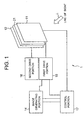
- FIG. 1 is a block diagram showing the constitution of the display unit according to the embodiment of the invention.
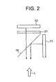
- FIG. 2 is a schematic cross-sectional view showing one embodiment of a display portion of the display unit.
- the display unit 1 comprises a front screen 11, a back screen 12 disposed in the rear of the front screen 11, an image generating portion 14 for generating an image displayed on the front screen 11 and the back screen 12, a first drive portion 15 for displaying an image signal from the image generating portion 14 on the front screen 11, a second drive portion 16 for displaying an image signal from the image generating portion 14 on the back screen 12, an optical distance setting portion 21 disposed between the front screen 11 and the rear screen 12, and a control portion 17 for controlling the entire display unit.
- the front screen 11 and the back screen 12 forms an image display portion of the display unit 1, and are disposed one after the other with a certain gap on the line of sight L of the observer.
- the front screen 11 is disposed in the fore, and the back screen 12 is disposed in the rear.
- the light transmissive display unit such as a liquid crystal display device or an EL display device is employed to allow the user to view the image on the back screen 12 in the rear transparently.
- the back screen 12 disposed in the rear may be a liquid crystal display device or EL display device, or a cathode ray tube display device or plasma display device owing to no necessity of light transmittance.
- the front screen 11 and the back screen 12 may have the same size or different sizes.
- the image is displayed on each of the front screen 11 and the back screen 12, whereby the observer recognizes the discrete stereoscopic image. Moreover, by increasing or decreasing its intensity, the stereoscopic image may be displayed as if the image appears between the front screen 11 and the back screen 12.
- the front screen 11 may be constituted of a cathode ray tube display device or plasma display device without having light transmittance rather than the liquid crystal display device or EL display device. That is, the front screen 11 is disposed before the back screen 12 not to intercept the line of sight L, with the half-mirror 18 provided on the line of sight of the observer, in which the angle of the half-mirror 18 is determined so that the image displayed on the front screen 11 is superposed on the image displayed on the back screen 12, as shown in FIG. 2. Thereby, the display unit without light transmittance is introduced into the front screen 11.
- the image generating portion 14 generates the images displayed on the front screen 11 and the back screen 12 and stores them. Also, the image input from the outside, for example, the image created on the personal computer, may be recorded in a predetermined recording area, and read, as needed.
- the images of unit are managed individually, and required to display independently. Which the image is displayed on the front screen 11 or the back screen 12 individually depends on the display position, size, luminosity, hue, display form, and image deformation.
- the first drive portion 15 and the second drive portion 16 drive the display on the front screen 11 and the back screen 12 on the basis of an image signal for the front screen 11 or the back screen 12 formed by the image generating portion 14.
- a function for ornamentally and effectively driving the display with the display timing or flashing under the control of the control portion 17 may be provided.
- the optical distance setting portion 21 sets the optical distance between the front screen 11 and the back screen 12 at a predetermined value that is different from the optical distance when the air is filled between both screens, whereby the image field (i.e., backward image field) of the image displayed on the back screen 12 is reflected forward or backward of the actual position on the back screen 12.
- the image field i.e., backward image field
- the optical distance setting portion 21 may form the image displayed on the back screen 12 at a different position from the actual position on the back screen 12, whereby the image field of the image displayed on the back screen 12 is reflected in the fore or rear of the actual position on the back screen 12.
- the control portion 17 performs the overall control of the display unit 1.
- the control portion 17 produces the image signals for displaying on the image generating portion 14 by setting the display forms such as intensity and size of the front screen 11 and the back screen 12 in displaying the stereoscopic image. Additionally, the control portion 17 controls the operation of the first drive portion 15 and the second drive portion 16.
- FIG. 3A shows schematically the principle for lengthening the apparent depth of the backward image field employing the optical distance setting portion in this embodiment
- FIG. 3B shows schematically the principle for shortening the apparent depth of the backward image field employing the optical distance setting portion in this embodiment.
- the display unit 1 comprises the front screen 11 and the back screen 12 disposed a distance L1 apart, in which the optical distance setting portion 21a containing a transparent member having the refractive index n1 ( ⁇ 1) that is smaller than the refractive index of the air is disposed in contact between the front screen 11 and the back screen 12.
- n1 is the refractive index of the optical distance setting portion 21a relative to the air.
- the optical distance setting portion 21a contains the transparent member having the refractive index smaller than the refractive index of the air, the optical distance (i.e., optical path length calculated in the air) when the optical distance setting portion 21a is replaced with the air is relatively longer. That is, the optical path length calculated in the air from the observer to the backward image field is relatively longer, whereby the apparent depth of the backward image field as seen from the observer is longer.
- the apparent backward image field 12a is reflected at a position distance La apart from the front screen 11 rearward of the actual position of the backward image field on the back screen 12 as seen from the side of the observer, whereby the observer recognizes as if the back screen 12 was disposed at the position of the apparent backward image screen 12a.
- the front screen 11 and the back screen 12 are disposed actually with interval L1, but disposed with a longer interval La than interval L1 optically or as seen from the side of the observer, whereby the substantially equivalent state is realized.
- the display unit 1 comprises the front screen 11 and the back screen 12 disposed distance L2 apart, in which the optical distance setting portion 21b containing the transparent member, for example, glass or resin, having the refractive index n2 ( ⁇ 1) that is larger than the refractive index of the air is disposed in contact with the front screen 11 and the back screen 12.
- n2 is the refractive index of the optical distance setting portion 21b relative to the air.
- the optical distance setting portion 21b contains the transparent member having the refractive index larger than the refractive index of the air, the optical distance (i.e., optical path length calculated in the air) when the optical distance setting portion 21b is replaced with the air is relatively shorter. That is, the optical path length calculated in the air from the observer to the backward image field is relatively shorter, whereby the apparent depth of the backward image field as seen from the observer is shorter.
- the apparent backward image field 12b is reflected at a position distance Lb apart from the front screen 11 forward of the actual position of the backward image field on the back screen 12 as seen from the side of the observer, whereby the observer recognizes as if the back screen 12 was disposed at the position of the apparent backward image screen 12b.
- the front screen 11 and the back screen 12 are disposed actually with interval L2, but disposed with a shorter interval Lb than interval L2 optically or as seen from the side of the observer, whereby the substantially equivalent state is realized.
- the optical distance setting portion 21a or the optical distance setting portion 21b are not contact with both the front screen 11 and the back screen 12, but may be contact with at least one of the front screen 11 and the back screen 12, or never contact with the front screen 11 and the back screen 12.
- the apparent depth of the backward image field is longer, the actual interval or device size is relatively smaller. Therefore, the entire device is reduced in size, and the thin conformation or portability is promoted. Conversely, if the apparent depth of the backward image field is shorter, the actual interval or device size is relatively larger. Therefore, it is possible to construct the display unit consisting of the plurality of display devices disposed in a desired size while meeting the structural restrictions with the projection such as fixing screw.
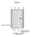
- FIG. 4 is a typical view showing a cross-sectional structure of a specific example in which the optical distance setting portion employs a transparent medium having a predetermined refractive index.
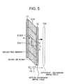
- FIG. 5 is a typical view showing the cross-sectional structure of a specific example in which the optical distance setting portion employs a transparent medium with a reflecting mirror.
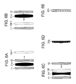
- FIG. 6A is a typical view showing the cross-sectional structure of a specific example in which the optical distance setting portion employs a convex lens
- FIG. 6B is a typical view showing the cross-sectional structure of another specific example in which the optical distance setting portion employs the convex lens, FIG.
- FIG. 6C is a typical view showing the cross-sectional structure of a specific example in which the optical distance setting portion employs a concave lens
- FIG. 6D is a typical view showing the cross-sectional structure of a Fresnel lens that is another specific example of the optical distance setting portion
- FIG. 6E is a typical view showing the cross-sectional structure of a micro-lens array that is another specific example of the optical distance setting portion.
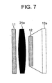
- FIG. 7 is a typical view showing the cross-sectional structure of the image display portion when the convex lens is employed as the optical distance setting portion.
- the optical distance setting portion 21c is made of at least one of glass and resin, and disposed between the front screen 11 and the back screen 12 disposed the distance L apart and in contact with both the front screen 11 and the back screen 12.
- the optical distance setting portion 21c contains at least one of glass and resin, and has a greater refractive index than the air. Therefore, the optical distance (i.e., optical path length calculated in the air) when the air is filled in the portion where the optical distance setting portion 21c is disposed is shorter than the actual optical distance when the optical distance setting portion 21c is disposed.
- the apparent interval as seen from the observer i.e., Lc
- the front screen 11 and the back screen 12 are actually disposed with the interval of 30 cm as seen from the side of the observer, but substantially equivalently disposed with an interval of 20 cm that is shorter than 30 cm optically or as seen from the side of the observer.
- the optical distance setting portion 21d disposed in contact between the front screen 11 and the back screen 12 disposed distance L apart contains glass or resin, and further comprises a plurality of (six in FIG. 5) reflecting mirrors like a window blind in the half open state inside the optical distance setting portion.
- the reflecting mirror reflects the image displayed on the back screen 12 to change the optical path of image in a direction that is different from the line of sight of the observer, and beyond the changed optical path, another reflecting mirror is disposed along the line of sight of the observer to change the optical path of image to cause light to proceed to the side of the observer.
- the optical distance setting portion 21d may have the plurality of reflecting mirrors in the air or another medium having a predetermined refractive index.
- the image displayed on the back screen 12 has the optical path parallel to the line of sight of the observer, in which light proceeds to the side of the observer to enter one reflecting mirror 21d-1 among the plurality of reflecting mirrors at an incident angle of 45 degrees, and be reflected at a reflection angle of 45 degrees. Due to reflection by the reflecting mirror 21d-1, the optical path is changed to that perpendicular to the line of sight of the observer, and made at an angle of 45 degrees to a reflecting mirror 21d-2 adjacent to the reflecting mirror 21d-1.
- the image is reversed by the reflecting mirror 21d-1.
- the image reflected by the reflecting mirror 21d-1 enters the reflecting mirror 21d-2 at an incident angle of 45 degrees, and is reflected at an angle of 45 degrees. That is, the image reflected by the reflecting mirror 21d-2 has the same optical path as the image before reflection by the reflecting mirror 21d-1, namely, the optical path that is in parallel to the line of sight of the observer and proceeds to the side of the observer.
- the image is further reversed by the reflecting mirror 21d-2, and restored to a normal state without reversion.
- the observer views the image displayed on the back screen 12 and reflected by the reflecting mirror in the same state as without being reflected by the reflecting mirror. That is, the optical path is lengthened by an optical path part between the reflecting mirror 21d-1 and the reflecting mirror 21d-2. That is, the backward image field 12d as seen from the side of the observer is located behind the actual position of the back screen 12.
- the reflecting mirror 21d-1 and the reflecting mirror 21d-2 are disposed distance L (i.e., the same distance as the interval between the front screen 11 and the back screen 12) apart, as shown in FIG. 5.
- L i.e., the same distance as the interval between the front screen 11 and the back screen 12
- light emitted from one pixel on the back screen 12 and light emitted from one pixel from the front screen 11 emitting light corresponding to its pixel are appropriately superposed on the line of sight of the observer.
- other reflecting mirrors are constituted in the same manner, the image for stereoscopic vision displayed on the front screen 11 and the back screen 12 are appropriately superposed and displayed on the line of sight of the observer.
- the image for stereoscopic vision displayed on the front screen 11 and the back screen 12 are appropriately superposed and displayed on the line of sight of the observer.
- the stereoscopic image is displayed by making the optical path length longer without being limited to the above distance.
- the number of reflecting mirrors provided for the optical distance setting portion 21d is varied with the distance by which the plurality of reflecting mirrors are separated.
- the optical path length is doubled due to reflection by the reflecting mirrors 21d-1 and 21 d-2 as compared with the optical distance setting portion 21d is not disposed.
- the apparent interval as seen from the observer i.e., Ld
- the front screen 11 and the back screen 12 are actually disposed with the interval of 30 cm as seen from the side of the observer, but substantially equivalently disposed with an interval of 40 cm that is longer than 30 cm optically or as seen from the side of the observer.
- the reflecting mirror is disposed in the air but not within the glass or resin, the optical path extended by the reflecting mirror is only considered, because it is unnecessary to consider a variation in the optical path length calculated in the air due to variation in the refractive index.
- the apparent depth of the backward image field is double the actual depth
- the front screen 11 and the back screen 12 are actually disposed with an interval of 30 cm apart.
- the front screen 11 and the back screen 12 are substantially equivalently disposed with an interval of 60 cm that is longer than 30 cm optically or as seen from the side of the observer.
- the image is reflected by the reflecting mirror and reversed. However, since the image is reflected twice, the image is not reversed and viewed by the observer. Also, the image is not reversed by the even number of reflections but not twice, when viewed by the observer. However, if the backward image field is reversed left or right, or upward or downward, by changing the signal contents in an input image signal or the drive operation in a driver circuit, the image is displayed without problem by the odd number of reflections.
- the image displayed on the back screen 12 has the apparent backward image field 12e reflected at a position decided in accordance with the focal distance of the convex lens 21e and the distance between the convex lens 21e and the back screen 12.
- the apparent backward image field 12e-1 is reflected backward of the actual position of the backward image field (i.e., position of the back screen 12) as seen from the side of the observer.
- the front screen and the back screen are substantially equivalently disposed with a longer interval than the actual interval optically or as seen from the side of the observer.
- the apparent backward image field 12e-2 is reflected forward of the actual position of the backward image field (i.e., position of the back screen 12) as seen from the side of the observer in accordance with the focal distance of the convex lens 21e and the distance between the convex lens 21e and the back screen 12. Accordingly, the front screen and the back screen are substantially equivalently disposed with a shorter interval than the actual interval optically or as seen from the side of the observer.
- the image displayed on the back screen 12 has the apparent backward image field 12f reflected at a position decided in accordance with the focal distance of the concave lens 21f and the distance between the concave lens 21f and the back screen 12. That is, the apparent depth of the backward image field is shorter, and the apparent backward image field 12f is reflected forward of the actual position of the backward image field (i.e., position of the back screen 12) as seen from the side of the observer. Accordingly, the front screen 11 and the back screen 12 are substantially equivalently disposed with a shorter interval than the actual interval optically or as seen from the side of the observer.
- a Fresnel lens 2 1 g may be employed as the optical distance setting portion 21.
- the Fresnel lens 21g has a smaller thickness of lens. Accordingly, the actual interval between the front screen 11 and the back screen 12 is further shortened.
- the display unit according to the embodiment of the invention is employed for the apparatus such as the portable telephone or PDA (Personal Digital Assistance) for which the reduced size is required, for example, the size is further reduced, and the thin conformation or portability is implemented.
- PDA Personal Digital Assistance
- a micro-lens array 21f may be employed as the optical distance setting portion 21.
- the micro-lens array 21f has a smaller thickness of lens, and is able to project at equal magnification. Therefore, the image is not formed in enlargement, unlike the convex lens. Accordingly, it is unnecessary that the front screen 11 and the back screen 12 are disposed in advance in different sizes in consideration of enlargement or reduction by the lens, as will be described later, whereby the display unit according to the embodiment of the invention is constituted, employing the front screen 11 and the back screen 12 of the equal size.
- the convex lens 21e is employed as the optical distance setting portion 21, and the back screen 12 smaller than the front screen 11 is disposed in advance.
- the observer who views the image on the back screen 12 via the convex lens 21e, recognizes the image as the apparent backward image field 12e larger than the actual size.
- the front screen 11 and the back screen 12 are disposed in advance in different sizes so that the enlarged image field (i.e., apparent backward image field 12e) on the back screen 12 may be viewed in the same size as the image field on the front screen 11 by the observer, in consideration of the enlargement of image.
- the back screen 12 is disposed in smaller size than the front screen 11. Thereby, the observer views the more natural stereoscopic image.
- the back screen 12 is disposed in advance in smaller size than the front screen 11, considering that the image is enlarged over the actual image size.
- the back screen 12 is disposed in advance in larger size than the front screen 11, considering that the image is reduced below the actual size on the screen.
- the image size adjusted by the image generating portion 14 may be changed, rather than the back screen 12 being disposed in advance in larger or smaller size than the front screen 11, so that the image on the back screen 12 be displayed in larger or smaller scale than the image on the front screen 11.
- the front screen 11 and the back screen 12 are within an appropriate range of size, whether the same or different size. That is, if the front screen 11 and the back screen 12 are within an appropriate range of size to the extent that the images on the front screen 11 and the back screen 12 are appropriately superposed, the observer views the stereoscopic image.
- the display unit according to the embodiment of the invention has two image display portions, when the display unit has three or more image display portions, a plurality of display devices can be disposed at a desired interval as an apparent interval by repeating the operation of changing the apparent interval between two adjacent image display portions in the above manner, even though the plurality of display devices are not disposed at the desired interval due to the requirements of physical shape.
Landscapes
- Engineering & Computer Science (AREA)
- Multimedia (AREA)
- Signal Processing (AREA)
- Testing, Inspecting, Measuring Of Stereoscopic Televisions And Televisions (AREA)
Abstract
It is an object of the invention to provide a display unit consisting of
a plurality of display devices which are substantially equivalently
disposed at an appropriate interval optically or as seen from the side of
the observer, even when the plurality of display devices are not disposed
at the appropriate interval due to some technical restrictions.
A display unit (1) is provided with a plurality of display devices
(11,12) disposed one after the other on the line of sight of the observer;
and an optical distance setting device (21), which is disposed between
two adjacent display devices among the plurality of display devices, for
setting the optical distance between the two display devices to a
predetermined value that is different from the optical distance when the
air is filled between the two display devices.
Description
The present invention relates to a display unit comprising a
plurality of display devices disposed one after the other in a line of sight
direction of the observer to provide a stereoscopic image by controlling
the images displayed on the display devices.
Conventionally, various types of apparatus capable of displaying a
stereoscopic image have been proposed or put to practical use. For
example, a liquid crystal shutter spectacle system is well known as an
apparatus for displaying the stereoscopic image that is electrically
rewritable. The liquid crystal shutter spectacles involve photographing
an object from different directions using a camera, and synthesizing the
acquired image data containing parallax information into one image
signal, which is then displayed on the display unit. The observer puts
on the liquid crystal shutter spectacles. For example, when in the odd
field, a liquid crystal shutter for right eye is turned in the transmission
state, and a liquid crystal shutter for left eye in the light shutout state.
On the other hand, when in the even field, the liquid crystal shutter for
left eye is turned in the transmission state, and the liquid crystal
shutter for right eye in the light shut-out state At this time, a
stereoscopic image is visualized by displaying an image for right eye in
the odd field and an image for left eye in the even field synchronously,
and viewing the images for right and left eyes containing parallax with
respective eyes.
Also, there is a display unit for displaying a stereoscopic image
that is discrete in the depth direction by superposing the images
displayed on a plurality of display devices, the display unit having a
plurality of display devices disposed one after the other on the line of
sight of the observer. Also, there is another display unit that is
improved to give a more natural stereoscopic sense by correcting the
discrete state, in which the intensity of image displayed on each display
device is varied so that an object is viewed at an intermediate position of
discrete positions. For example, a display unit of intensity modulation
type has been proposed in which the object images from a plurality of
display devices are superposed, employing a plurality of half mirrors, so
that a translucent object or a rear object is viewed transparently (e.g.,
refer to patent document 1).
[Patent document 1]
Japanese Patent Laid-Open No. 2000-115812
[Patent document 1]
Japanese Patent Laid-Open No. 2000-115812
By the way, a display unit having a plurality of display devices
disposed one after the other on the line of sight of the observer has an
appropriate interval between the plurality of display devices to display
the stereoscopic image.
However, when the plurality of display devices are disposed on
the basis of the appropriate interval, there are some restrictions on the
unit specifications to impede the realization of the display unit. Or
when the plurality of display devices are disposed on the basis of the
appropriate interval, it is often difficult or impossible to meet those
restrictions. For example, when the appropriate interval is longer, the
volume of the display unit is increased. Therefore, there is an
inconvenience that it is technically difficult to reduce the display unit in
size in consideration of thin conformation or portability. On the other
hand, when the appropriate interval is shorter, it is necessary to place
the plurality of display devices in proximity. However, there is another
technical inconvenience that the plurality of display devices can not be
disposed at a shorter interval in some cases due to the projection such
as a fixing screw, for example.
The present invention has been achieved in the light of the above-mentioned
inconveniences, and it is an object of the invention to
provide a display unit consisting of a plurality of display devices which
are substantially equivalently disposed at an appropriate interval
optically or as seen from the side of the observer, even when the
plurality of display devices are not disposed at the appropriate interval
due to some technical restrictions.
The above object of the present invention can be achieved by a
display unit of the present invention. The display unit is provided with
a plurality of display devices disposed one after the other on the line of
sight of the observer; and an optical distance setting device, which is
disposed between two adjacent display devices among the plurality of
display devices, for setting the optical distance between the two display
devices to a predetermined value that is different from the optical
distance when the air is filled between the two display devices.
According to the present invention, in operation, a display unit
displays a stereoscopic or three-dimensional image by superposing the
images on a plurality of display devices disposed one after the other on
the line of sight of the observer to make the stereoscopic vision as seen
from the side of the observer.
In one aspect of the present invention can be achieved by the
display unit of the present invention. The display unit is wherein the
optical distance setting device comprises a transparent member having
a predetermined refractive index.
According to the present invention, the optical distance between
two display devices can be changed by passing light through the
transparent member having a larger refractive index than the air, while
the interval between two display devices is actually fixed.
In another aspect of the present invention can be achieved by the
display unit of the present invention. The display unit is wherein the
transparent member is composed of at least one of glass and resin
having a higher refractive index than the air.
According to the present invention, the optical path length
calculated in the air between two display devices is relatively shortened
with relative easy by passing light through the transparent member
containing glass or resin having a higher refractive index than the air.
In further aspect of the present invention can be achieved by the
display unit of the present invention. The display unit is wherein the
optical distance setting device is provided with a reflecting member for
making the optical path length between the two display devices longer
than the optical path length when the air is filled by folding and
lengthening the optical path between the two display devices.
According to the present invention, the optical path length is
longer than the interval between two display devices in which the air is
simply filled without intervention of the reflecting member, whereby the
observer recognizes as if the display device disposed in the rear of the
reflecting member was disposed further in the rear by the amount of
longer optical path. That is, the apparent depth of the backward image
field as seen from the observer is lengthened.
In further aspect of the present invention can be achieved by the
display unit of the present invention. The display unit is wherein the
reflecting member is provided corresponding to each pixel or each pixel
block or pixel line composed of plural pixels in the two display devices,
in which the reflecting member folds the optical path so that the images
displayed at the pixel or the pixel block or pixel line in the two display
devices correspond.
According to the present invention, the display content of image
such as lightness is at the same level in pixel unit, whereby the
appropriate image is also displayed by reflection of the reflecting
member. Thereby, it is possible to view the stereoscopic image that is
appropriately unified as a whole.
The above object of the present invention can be achieved by a
display unit of the present invention. The display unit is provided with
a plurality of display devices disposed one after the other on the line of
sight of the observer; and an image-forming device, which is disposed
between two adjacent display devices among the plurality of display
devices, for forming an image displayed on a display device disposed in
the rear as seen from the side of the observer among the two display
devices at a different position from the position of the display device
disposed in the rear.
According to the present invention, even when the plurality of
display devices are not disposed at appropriate interval due to some
technical restrictions, the plurality of display devices are substantially
equivalently disposed at appropriate interval optically or as seen from
the side of the observer.
In one aspect of the present invention can be achieved by the
display unit of the present invention. The display unit is wherein the
image-forming device comprises a lens.
According to the present invention, the image displayed on the
display device disposed in the rear of the lens among two display
devices is formed at a different position from the position of display
device disposed in the rear in accordance with the focal distance of the
lens. That is, if the focal distance of the lens is set at a predetermined
value, it is possible to make the apparent depth of the backward image
field longer or shorter relatively easily.
In another aspect of the present invention can be achieved by the
display unit of the present invention. The display unit is wherein the
lens comprises a convex lens.
According to the present invention, by using a convex lens
disposed between two display devices, the image displayed on the
display device disposed in the rear of the convex lens among two display
devices is formed in the rear of the position of the display device
disposed in the rear.
In further aspect of the present invention can be achieved by the
display unit of the present invention. The display unit is wherein the
lens comprises a concave lens.
According to the present invention, by using a concave lens
disposed between two display devices, the image displayed on the
display device disposed in the rear of the concave lens among two
display devices is formed in the fore of the position of the display device
disposed in the rear.
In further aspect of the present invention can be achieved by the
display unit of the present invention. The display unit is wherein the
lens comprises a Fresnel lens.
According to the present invention, the thickness of the lens is
made smaller using a Fresnel lens. Thereby, the device is reduced in
the size, and the thin conformation or portability is promoted.
In further aspect of the present invention can be achieved by the
display unit of the present invention. The display unit is wherein the
lens comprises a micro-lens array.
According to the present invention, the thickness of the lens is
made smaller using a micro-lens array, and a variation in the
magnification of the image formed is reduced.
In further aspect of the present invention can be achieved by the
display unit of the present invention. The display unit is wherein the
lens corresponds to each pixel or each pixel block or pixel line
composed of plural pixels in the plurality of display devices.
According to the present invention, one lens corresponds to each
pixel or each pixel block or pixel line of the plurality of display devices.
Therefore, the luminosity or degree of image formation is at the same
level for all the pixels, whereby it is possible to display the stereoscopic
image that is unified as a whole. Moreover, the constitution of lens
array is simplified by employing the lens array in which one lens
corresponds to each pixel block or pixel line.
In further aspect of the present invention can be achieved by the
display unit of the present invention. The display unit is wherein the
screen of each of one or more display devices disposed in the rear of the
image-forming device as seen from the side of the observer among the
plurality of display devices and the screen of each of one or more
display devices disposed in the fore of the image-forming device as seen
from the side of the observer among the plurality of display devices have
different sizes.
According to the present invention, the image displayed on one or
more display devices disposed in the rear of the lens as seen from the
side of the observer among the plurality of display devices is enlarged or
reduced via the lens. However, in this embodiment, the images are
naturally superposed in consideration of this enlargement or reduction.
That is, the observer views the images displayed on the plurality of
display devices at the same or almost same magnitude and thus
recognizes the superposed image.
In further aspect of the present invention can be achieved by the
display unit of the present invention. The display unit is wherein the
screens have different sizes so that each pixel or each pixel block or
pixel line composed of plural pixels in the plurality of display devices
have the same size between the display device disposed in the rear and
the display device disposed in the fore as seen from the side of the
observer and be superposed.
According to the present invention, even though the images are
enlarged or reduced and superposed by the lens disposed between two
display devices, the images are superposed in consideration of the
enlargement or reduction, whereby it is possible to view the excellent
image as seen from the observer.
In further aspect of the present invention can be achieved by the
display unit of the present invention. The display unit is wherein the
optical distance setting device is intimately contact with at least one of
the two display devices.
According to the present invention, even if the optical distance
setting device is contact with at least one of two display devices, two
display devices can be disposed at a shorter or longer interval optically
or as seen from the side of the observer than the actual interval between
two display devices. In this case, the optical distance setting device
may be contact with one or both of the two display devices.
In further aspect of the present invention can be achieved by the
display unit of the present invention. The display unit is wherein the
image-forming device is intimately contacted with at least one of the two
display devices.
According to the present invention, even if the image-forming
device is contact with at least one of two display devices, two display
devices can be disposed at a shorter or longer interval optically or as
seen from the side of the observer than the actual interval between two
display devices. In this case, the image-forming device may be contact
with only one or both of the two display devices.
In further aspect of the present invention can be achieved by the
display unit of the present invention. The display unit is wherein the
display devices are translucent at least except for the display device
farthest away from the observer among the plurality of display devices.
According to the present invention, the image displayed on the
display device disposed in the rear is viewed through the display device
disposed in the fore as seen from the observer, and the display device is
directly disposed on the line of sight of the observer.
In further aspect of the present invention can be achieved by the
display unit of the present invention. The display unit is wherein the
translucent display device is a liquid crystal display device or EL
(Electro-Luminescence) display device.
According to the present invention, the stereoscopic image is
displayed, employing a translucent panel-like display device such as an
EL display device.
In further aspect of the present invention can be achieved by the
display unit of the present invention. The display unit is wherein the
plurality of display devices is provided with a display device synthesized
of a half mirror.
According to the present invention, the display device without
light transmittance may be employed as the display device, for example,
a cathode ray tube display device and a plasma display device.
The preferred embodiments of the present invention are described
below.
A display unit concerning a first embodiment of the invention is
provided with a plurality of display devices disposed one after the other
on the line of sight of the observer; and an optical distance setting
device, which is disposed between two adjacent display devices among
the plurality of display devices, for setting the optical distance between
the two display devices to a predetermined value that is different from
the optical distance when the air is filled between the two display
devices.
According to a first embodiment of the invention, in operation, a
display unit displays a stereoscopic or three-dimensional image by
superposing the images on a plurality of display devices disposed one
after the other on the line of sight of the observer to make the
stereoscopic vision as seen from the side of the observer. That is, the
observer can view a stereoscopic image. For example, for a stereoscopic
display of intensity modulation type, the same image portion displayed
by two adjacent display devices (hereinafter adequately referred to as
"two display devices") is allocated intensity, so that an image appears to
exist at a depth position between two display devices, thereby allowing
the continuous stereoscopic display. Or the image portion may be
displayed on either of two display devices to enable the discrete
stereoscopic display. Moreover, the continuous or discrete stereoscopic
display is enabled in which an image appears to exist at any one
position across three or more display devices.
Particularly in this embodiment, an optical distance setting device
is disposed between two display devices, and the optical distance
between two display devices is set to a predetermined value that is
different from the optical distance when the air is filled between two
display devices. The term "optical distance" as herein used is the
distance optically calculated, or the apparent distance as seen from the
side of the observer. And the observer views an image field on a display
device located in the rear (back) among two display devices with
reference to the observer (hereinafter appropriately referred to as a
"backward image field") via the optical distance setting device.
Accordingly, the observer views the image via the optical distance
setting device, and recognizes the image field (i.e., backward image field)
at a different position (i.e., an apparent depth position) from the
position at which the display device is actually disposed. Accordingly,
the interval between two display devices can be different from the actual
interval optically or as seen from the side of the observer.
Thereby, while two display devices are substantially equivalently
disposed at appropriate interval as seen optically in making the
stereoscopic display, two display devices can be disposed actually at a
shorter or longer interval than the interval between two display devices
appropriately disposed in the air. In other words, for example, even
when a plurality of display devices are not disposed at appropriate
interval due to some technical restrictions, the plurality of display
devices are substantially equivalently disposed at appropriate interval
optically or as seen from the side of the observer.
In the display unit having three or more display devices, three or
more display devices are substantially equivalently disposed at
appropriate interval by taking into consideration all the optical lengths
calculated in the air between the adjacent display devices.
According to a display unit concerning a first embodiment of the
invention, the optical distance setting device includes a transparent
member having a predetermined refractive index.
In this embodiment, the optical distance setting device comprises
a transparent member having a predetermined refractive index, for
example, made of glass, whereby the optical distance can be set at a
predetermined value by passing light through the transparent member.
Accordingly, the optical distance between two display devices can be
changed by passing light through the transparent member having a
larger refractive index than the air, while the interval between two
display devices is actually fixed. In this case, the optical path length
calculated in the air from the observer to the backward image field is
the depth (or apparent depth) of the backward image field as seen from
the observer. The term "optical path length calculated in the air" as
used herein is the imaginary optical path length in which the optical
path length is calculated in the air by replacing the optical distance
setting device with the air. Assuming that this value is LA, LA is
represented by L/n. Where L is the thickness of the optical distance
setting device, and coincides with the optical path length between two
display devices (i.e., actual interval between two display devices) when
the optical distance setting device is filled between two display devices.
Also, n is the refractive index of the material or medium making up the
optical distance setting device.
Accordingly, it is possible to lengthen the actual interval between
two display devices by shortening relatively the optical path length (i.e.,
apparent depth) calculated in the air. Conversely, it is possible to
shorten the actual interval between two display devices by passing light
through the member or medium having a smaller refractive index than
the air or through the vacuum to lengthen the optical path length (i.e.,
apparent depth) calculated in the air, while the actual interval between
two display devices is fixed.
For example, if the optical path length (LA = L/n) calculated in
the air is set to be relatively longer by making the refractive index n
between two display devices is lower than in the air, and the actual
interval between two display devices is shorter, the unit is reduced in
size, and the thin conformation or portability is promoted. Conversely,
if the optical path length (LA = L/n) calculated in the air is set to be
relatively shorter by making the refractive index n between two display
devices higher than in the air, and the actual interval between two
display devices is lengthened, the display device or display unit can be
constituted in the size not to interfere with a projection such as a fixing
screw, if any.
In this embodiment, the transparent member includes at least
one of glass and resin having a higher refractive index than the air.
With this constitution, the optical path length calculated in the
air between two display devices is relatively shortened relatively easily
by passing light through the transparent member containing glass or
resin having a higher refractive index than the air.
A display unit concerning a first embodiment of the invention, the
optical distance setting device includes a reflecting member for making
the optical path length between the two display devices longer than the
optical path length when the air is filled by folding and lengthening the
optical path between the two display devices.
In this embodiment, an image displayed on the display device
disposed in the rear of the reflecting member comprising the reflecting
mirror as seen from the side of the observer among two display devices
is reflected by the reflecting member, and passed through the optical
path lengthened by folding, after which the observer views the image
through the longer optical path. For example, the image is reflected by
the reflecting member, so that the optical path of the image is changed
in a direction that is different from the line of sight of the observer, and
ahead of its changed optical path, further changed by another reflecting
member in the same direction as the line of sight of the observer to
allow light to proceed to the side of the observer. Accordingly, the
optical path length is longer by the length of optical path changed by
reflection as compared with when the image is not reflected by the
reflecting member, namely, when the optical path is linear. That is, the
optical path length can be longer than the interval between two display
devices in which the air is simply filled without intervention of the
reflecting member, whereby the observer recognizes as if the display
device disposed in the rear of the reflecting member was disposed
further in the rear by the amount of longer optical path. That is, the
apparent depth of the backward image field as seen from the observer is
lengthened.
The reflecting member is not limited to the reflecting mirror, but
may be a predetermined member capable of reflecting light
appropriately to achieve the same effect.
Thereby, the optical path length calculated in the air between two
display devices is made relatively longer, so that the actual length
between two display devices is shortened.
The reflection of the reflecting member is not limited to two
reflections as described above, but may be even reflections, in which the
optical path is changed by the reflecting member at the last stage to
allow light to proceed to the side of the observer along the line of sight of
the observer. That is, owing to the even reflections, there is no need for
considering the reversion of the image by total reflection. Also, if the
optical path is along the line of sight of the observer by the final
reflection to allow light to proceed to the side of the observer, the
observer can directly view the image displayed on two display devices.
However, even with odd reflections, if the image displayed on the display
device is reversed in advance and displayed, the optical distance setting
device employing the above reflecting member may be constituted.
The reflecting member is provided corresponding to each pixel or
each pixel block or pixel line composed of plural pixels in the two
display devices, in which the reflecting member folds the optical path so
that the images displayed at the pixel or the pixel block or pixel line in
the two display devices correspond.
With the above constitution, one reflecting member corresponds
to each pixel or each pixel block or pixel line in two display devices.
Therefore, the image (i.e., emitted light) displayed at each pixel or each
pixel block or pixel line on the display device disposed in the rear as
seen from the side of the observer among two display devices is
superposed and displayed on the image displayed at each pixel or each
pixel block or pixel line on the display device disposed in the fore as
seen from the side of the observer among two display devices on the line
of sight of the observer. Accordingly, even if the optical path length is
lengthened by the reflecting member, the observer can view the
stereoscopic image by appropriately superposing the two images. In
addition, the display content of image such as lightness is at the same
level in pixel unit, whereby the appropriate image is also displayed by
reflection of the reflecting member. Thereby, it is possible to view the
stereoscopic image that is appropriately unified as a whole.
A display unit concerning a second embodiment of the present
invention is provided with a plurality of display devices disposed one
after the other on the line of sight of the observer; and an image-forming
device, which is disposed between two adjacent display devices among
the plurality of display devices, for forming an image displayed on a
display device disposed in the rear as seen from the side of the observer
among the two display devices at a different position from the position
of the display device disposed in the rear.
According to a second embodiment of the invention, in operation,
a display unit displays a stereoscopic or three-dimensional image by
superposing the images on a plurality of display devices disposed one
after the other on the line of sight of the observer to make the
stereoscopic vision as seen from the side of the observer. For example,
for a stereoscopic display of intensity modulation type, the same image
portion displayed by two adjacent display devices is allocated intensity,
so that an image appears to exist at a depth position between two
display devices, thereby allowing the continuous stereoscopic display.
Or the image portion may be displayed on either of two display devices
to enable the discrete stereoscopic display. Moreover, the continuous or
discrete stereoscopic display is enabled in which an image appears to
exist at any one position across three or more display devices.
Particularly in this embodiment, an image-forming device is
disposed between two display devices, whereby the image (i.e.,
backward image field) displayed on the display device disposed in the
rear of the image-forming device as seen from the side of the observer is
formed in front of or behind the display device disposed in the rear.
Accordingly, the observer views the image displayed on the display
device via the image-forming device and thus recognizes the image field
formed at a different position from the actual position of the display
device. That is, the apparent depth of the backward image field as seen
from the side of the observer can be longer or shorter.
Thereby, while the plurality of display devices are substantially
equivalently disposed at appropriate interval as optically seen in making
the stereoscopic display, namely, the interval between two display
devices is made equivalent to that when no image-forming device is
disposed between two display devices by employing the image-forming
device, two display devices are disposed at a shorter or longer interval
than the actual interval between two display devices when no image-forming
device is disposed. In other words, for example, even when the
plurality of display devices are not disposed at appropriate interval due
to some technical restrictions, the plurality of display devices are
substantially equivalently disposed at appropriate interval optically or
as seen from the side of the observer.
For example, if the backward image field is formed further
backward by the image-forming device to lengthen the apparent depth
of the backward image field as seen from the side of the observer, the
actual interval or device size is relatively reduced. Therefore, the total
size of the device is reduced, and the thin conformation or portability is
promoted. Conversely, if the backward image field is formed further
forward (i.e., on the fore side as seen from the observer) to shorten the
apparent depth of the backward image field, the actual interval or
device size is relatively increased. Therefore, it is possible to construct
the display unit having the plurality of display devices disposed in a
desired size while meeting the structural restrictions due to the
projection such as fixing screw.
In the display unit having three or more display devices, three or
more display devices are substantially equivalently disposed at
appropriate interval by taking into consideration the apparent depth of
the image displayed on each of one or more display devices disposed in
the rear of the image-forming device among three or more display
devices.
In one embodiment of the display unit, the image-forming device
includes a lens.
With this constitution, the image displayed on the display device
disposed in the rear of the lens among two display devices is formed at
a different position from the position of display device disposed in the
rear in accordance with the focal distance of the lens. That is, if the
focal distance of the lens is set at a predetermined value, it is possible
to make the apparent depth of the backward image field longer or
shorter relatively easily.
In one embodiment of the display unit, the lens comprises a
convex lens.
With this constitution, using a convex lens disposed between two
display devices, the image displayed on the display device disposed in
the rear of the convex lens among two display devices is formed in the
rear of the position of the display device disposed in the rear. Or the
image displayed on the display device disposed in the rear of the convex
lens among two display devices is formed in the fore of the position of
the display device disposed in the rear. That is, it is possible to make
the apparent depth of the backward image field as seen from the
observer longer or shorter relatively easily. In one embodiment of the
display unit, the lens includes a concave lens.
With this constitution, using a concave lens disposed between two
display devices, the image displayed on the display device disposed in
the rear of the concave lens among two display devices is formed in the
fore of the position of the display device disposed in the rear. That is, it
is possible to make the apparent depth of the backward image field as
seen from the observer shorter relatively easily.
In a display unit of an embodiment, the lens includes a Fresnel
lens.
With this constitution, the thickness of the lens is made smaller
using a Fresnel lens. Thereby, the device is reduced in the size, and the
thin conformation or portability is promoted.
In a display unit of an embodiment, the lens includes a micro-lens
array.
With this constitution, the thickness of the lens is made smaller
using a micro-lens array, and a variation in the magnification of the
image formed is reduced.
Moreover, in the embodiment of the display unit having the
image-forming device comprising various kinds of lens, it is possible to
select the optimal or preferable embodiment of lens on the basis of the
use embodiment or condition of the display unit.
Also, the lens may be a focus variable lens, an aspherical lens or
a distributed refractive index lens, rather than the convex lens, the
concave lens, the Fresnel lens, and the micro-lens array.
In an embodiment of the display unit concerning a second
embodiment of the present invention, the lens corresponds to each pixel
or each pixel block or pixel line composed of plural pixels in the
plurality of display devices.
With the above constitution, one lens corresponds to each pixel or
each pixel block or pixel line of the plurality of display devices.
Therefore, the luminosity or degree of image formation is at the same
level for all the pixels, whereby it is possible to display the stereoscopic
image that is unified as a whole. Moreover, the constitution of lens
array is simplified by employing the lens array in which one lens
corresponds to each pixel block or pixel line.
In an other embodiment of the display unit concerning a second
embodiment of the present invention, the screen of each of one or more
display devices disposed in the rear of the image-forming device as seen
from the side of the observer among the plurality of display devices and
the screen of each of one or more display devices disposed in the fore of
the image-forming device as seen from the side of the observer among
the plurality of display devices have different sizes.
When the image-forming device comprises the lens as above, the
image displayed on one or more display devices disposed in the rear of
the lens as seen from the side of the observer among the plurality of
display devices is enlarged or reduced via the lens. However, in this
embodiment, the images are naturally superposed in consideration of
this enlargement or reduction. That is, the observer views the images
displayed on the plurality of display devices at the same or almost same
magnitude and thus recognizes the superposed image.
Also, it may be possible to reduce or enlarge beforehand the
image displayed on each of one or more display devices disposed in the
rear, instead of or in addition to reducing or enlarging beforehand the
screen of one or more display devices disposed in the rear.
However, even if the display device disposed in the rear and the
display device disposed in the fore are of the equal size, or the image
displayed on the display device disposed in the rear is not reduced or
enlarged beforehand, the images displayed on two display devices are
superposed to the extent that the observer can view the stereoscopic
image.
The screens have different sizes or same sizes so that each pixel
or each pixel block or pixel line composed of plural pixels in the
plurality of display devices may have the same size between the display
device disposed in the rear and the display device disposed in the fore
as seen from the side of the observer and be superposed.
In the display unit in which the display device disposed in the
rear and the display device disposed in the fore have different sizes as
described above, the screens may be different sizes so far as each pixel
or each pixel block or pixel line composed of plural pixels in the
plurality of display devices has the same size between the display device
disposed in the rear and the display device disposed in the fore as seen
from the side of the observer and be superposed.
With this constitution, even though the images are enlarged or
reduced and superposed by the lens disposed between two display
devices, the images are superposed in consideration of the enlargement
or reduction, whereby it is possible to view the excellent image as seen
from the observer. The term "same size" as used herein means literally
the same size, as well as the substantially same size to the extent that
plural images of the same object superposed appear the same size
visually for the observer.
In other embodiment of the display unit concerning a second
embodiment of the present invention, the optical distance setting device
is intimately contact with at least one of the two display devices.
In this embodiment, even if the optical distance setting device is
contact with at least one of two display devices, two display devices can
be disposed at a shorter or longer interval optically or as seen from the
side of the observer than the actual interval between two display
devices. In this case, the optical distance setting device may be contact
with one or both of the two display devices.
Even if the optical distance setting device is not contact with at
least one of two display devices, the plurality of display devices can be
disposed at a shorter or longer interval optically or as seen from the side
of the observer than the actual interval between two display devices.
In other embodiment of the display unit concerning a second
embodiment of the present invention, the image-forming device is
intimately contacted with at least one of the two display devices.
In this embodiment, even if the image-forming device is contact
with at least one of two display devices, two display devices can be
disposed at a shorter or longer interval optically or as seen from the side
of the observer than the actual interval between two display devices. In
this case, the image-forming device may be contact with only one or
both of the two display devices.
Even if the image-forming device is not contact with at least one
of two display devices, the plurality of display devices can be disposed
at a shorter or longer interval optically or as seen from the side of the
observer than the actual interval between two display devices.
In other embodiment of the display unit concerning a first
embodiment and a second embodiment of the present invention, the
display devices are translucent at least except for the display device
farthest away from the observer among the plurality of display devices.
In this embodiment, the image displayed on the display device
disposed in the rear is viewed through the display device disposed in
the fore as seen from the observer, and the display device is directly
disposed on the line of sight of the observer.
In other embodiment of the display unit concerning a first
embodiment and a second embodiment of the present invention, the
translucent display device is a liquid crystal display device or EL
(Electro-Luminescence) display device.
With this constitution, the stereoscopic image is displayed,
employing a translucent panel-like display device such as a liquid
crystal display device or an EL display device.
In other embodiment of the display unit concerning a first
embodiment and a second embodiment of the present invention, the
plurality of display devices comprise a display device synthesized of a
half mirror.
In this embodiment, the plurality of display devices is not directly
disposed on the line of sight of the observer, and the images are
synthesized via the half-mirror. Accordingly, the display device without
light transmittance may be employed as the display device, for example,
a cathode ray tube display device and a plasma display device.
As described above, with the display device according to the
embodiment of the invention, the plurality of display devices and the
optical distance setting device or image-forming device may be provided.
Therefore, the interval between two display devices can be different from
the actual interval optically or as seen from the side of the observer.
That is, the plurality of display devices are substantially equivalently
disposed at an appropriate interval optically or as seen from the side of
the observer, even when the plurality of display devices can not be
disposed at the appropriate interval due to some technical restrictions.
Also, with the embodiment of the invention, the same effect can be
attained whether the moving picture or still image.
This action and other benefits of this embodiment will be further
clear from the following description.
A display unit of the present invention will be described below by
way of example with reference to the accompanying drawings.
Referring to FIG. 1 and FIG. 2, the operation principle and basic
constitution of a display unit according to an embodiment of the
invention will be described below. FIG. 1 is a block diagram showing
the constitution of the display unit according to the embodiment of the
invention. FIG. 2 is a schematic cross-sectional view showing one
embodiment of a display portion of the display unit.
As shown in FIG. 1, the display unit 1 comprises a front screen
11, a back screen 12 disposed in the rear of the front screen 11, an
image generating portion 14 for generating an image displayed on the
front screen 11 and the back screen 12, a first drive portion 15 for
displaying an image signal from the image generating portion 14 on the
front screen 11, a second drive portion 16 for displaying an image signal
from the image generating portion 14 on the back screen 12, an optical
distance setting portion 21 disposed between the front screen 11 and
the rear screen 12, and a control portion 17 for controlling the entire
display unit.
The front screen 11 and the back screen 12 forms an image
display portion of the display unit 1, and are disposed one after the
other with a certain gap on the line of sight L of the observer. The front
screen 11 is disposed in the fore, and the back screen 12 is disposed in
the rear. For the front screen 11, the light transmissive display unit
such as a liquid crystal display device or an EL display device is
employed to allow the user to view the image on the back screen 12 in
the rear transparently. Also, the back screen 12 disposed in the rear
may be a liquid crystal display device or EL display device, or a cathode
ray tube display device or plasma display device owing to no necessity
of light transmittance. The front screen 11 and the back screen 12 may
have the same size or different sizes.
The image is displayed on each of the front screen 11 and the
back screen 12, whereby the observer recognizes the discrete
stereoscopic image. Moreover, by increasing or decreasing its intensity,
the stereoscopic image may be displayed as if the image appears
between the front screen 11 and the back screen 12.
The front screen 11 may be constituted of a cathode ray tube
display device or plasma display device without having light
transmittance rather than the liquid crystal display device or EL display
device. That is, the front screen 11 is disposed before the back screen
12 not to intercept the line of sight L, with the half-mirror 18 provided
on the line of sight of the observer, in which the angle of the half-mirror
18 is determined so that the image displayed on the front screen 11 is
superposed on the image displayed on the back screen 12, as shown in
FIG. 2. Thereby, the display unit without light transmittance is
introduced into the front screen 11.
Referring to FIG. 1 again, the image generating portion 14
generates the images displayed on the front screen 11 and the back
screen 12 and stores them. Also, the image input from the outside, for
example, the image created on the personal computer, may be recorded
in a predetermined recording area, and read, as needed. The images of
unit are managed individually, and required to display independently.
Which the image is displayed on the front screen 11 or the back screen
12 individually depends on the display position, size, luminosity, hue,
display form, and image deformation.
The first drive portion 15 and the second drive portion 16 drive
the display on the front screen 11 and the back screen 12 on the basis
of an image signal for the front screen 11 or the back screen 12 formed
by the image generating portion 14. A function for ornamentally and
effectively driving the display with the display timing or flashing under
the control of the control portion 17 may be provided.
In this embodiment, particularly, the optical distance setting
portion 21 sets the optical distance between the front screen 11 and the
back screen 12 at a predetermined value that is different from the
optical distance when the air is filled between both screens, whereby
the image field (i.e., backward image field) of the image displayed on the
back screen 12 is reflected forward or backward of the actual position
on the back screen 12.
The optical distance setting portion 21 may form the image
displayed on the back screen 12 at a different position from the actual
position on the back screen 12, whereby the image field of the image
displayed on the back screen 12 is reflected in the fore or rear of the
actual position on the back screen 12.
The control portion 17 performs the overall control of the display
unit 1. The control portion 17 produces the image signals for displaying
on the image generating portion 14 by setting the display forms such as
intensity and size of the front screen 11 and the back screen 12 in
displaying the stereoscopic image. Additionally, the control portion 17
controls the operation of the first drive portion 15 and the second drive
portion 16.
Referring to FIG. 3, a principle for setting the optical distance by
the optical distance setting portion provided for the display unit
according to the embodiment of the invention will be described below.
Herein, FIG. 3A shows schematically the principle for lengthening the
apparent depth of the backward image field employing the optical
distance setting portion in this embodiment, and FIG. 3B shows
schematically the principle for shortening the apparent depth of the
backward image field employing the optical distance setting portion in
this embodiment.
As shown in FIG. 3A, the display unit 1 according to the
embodiment of the invention comprises the front screen 11 and the
back screen 12 disposed a distance L1 apart, in which the optical
distance setting portion 21a containing a transparent member having
the refractive index n1 (≤1) that is smaller than the refractive index of
the air is disposed in contact between the front screen 11 and the back
screen 12. Where n1 is the refractive index of the optical distance
setting portion 21a relative to the air.
Since the optical distance setting portion 21a contains the
transparent member having the refractive index smaller than the
refractive index of the air, the optical distance (i.e., optical path length
calculated in the air) when the optical distance setting portion 21a is
replaced with the air is relatively longer. That is, the optical path length
calculated in the air from the observer to the backward image field is
relatively longer, whereby the apparent depth of the backward image
field as seen from the observer is longer. Herein, the optical path length
La calculated in the air is indicated by La = L1/n1. Accordingly, the
apparent backward image field 12a is reflected at a position distance La
apart from the front screen 11 rearward of the actual position of the
backward image field on the back screen 12 as seen from the side of the
observer, whereby the observer recognizes as if the back screen 12 was
disposed at the position of the apparent backward image screen 12a.
Accordingly, the front screen 11 and the back screen 12 are disposed
actually with interval L1, but disposed with a longer interval La than
interval L1 optically or as seen from the side of the observer, whereby
the substantially equivalent state is realized.
As shown in FIG. 3B, the display unit 1 according to the
embodiment of the invention comprises the front screen 11 and the
back screen 12 disposed distance L2 apart, in which the optical
distance setting portion 21b containing the transparent member, for
example, glass or resin, having the refractive index n2 (≥1) that is larger
than the refractive index of the air is disposed in contact with the front
screen 11 and the back screen 12. Where n2 is the refractive index of
the optical distance setting portion 21b relative to the air.
Since the optical distance setting portion 21b contains the
transparent member having the refractive index larger than the
refractive index of the air, the optical distance (i.e., optical path length
calculated in the air) when the optical distance setting portion 21b is
replaced with the air is relatively shorter. That is, the optical path
length calculated in the air from the observer to the backward image
field is relatively shorter, whereby the apparent depth of the backward
image field as seen from the observer is shorter. Herein, the optical
path length Lb calculated in the air is indicated by Lb = L2/n2.
Accordingly, the apparent backward image field 12b is reflected at a
position distance Lb apart from the front screen 11 forward of the
actual position of the backward image field on the back screen 12 as
seen from the side of the observer, whereby the observer recognizes as if
the back screen 12 was disposed at the position of the apparent
backward image screen 12b. Accordingly, the front screen 11 and the
back screen 12 are disposed actually with interval L2, but disposed with
a shorter interval Lb than interval L2 optically or as seen from the side
of the observer, whereby the substantially equivalent state is realized.
The optical distance setting portion 21a or the optical distance
setting portion 21b are not contact with both the front screen 11 and
the back screen 12, but may be contact with at least one of the front
screen 11 and the back screen 12, or never contact with the front
screen 11 and the back screen 12.
As will be clear from the above description, if the apparent depth
of the backward image field is longer, the actual interval or device size is
relatively smaller. Therefore, the entire device is reduced in size, and
the thin conformation or portability is promoted. Conversely, if the
apparent depth of the backward image field is shorter, the actual
interval or device size is relatively larger. Therefore, it is possible to
construct the display unit consisting of the plurality of display devices
disposed in a desired size while meeting the structural restrictions with
the projection such as fixing screw.
Referring to FIGS. 4 to 7, various specific examples of the optical
distance setting portion that is adopted in this embodiment will be
described below. Herein, FIG. 4 is a typical view showing a cross-sectional
structure of a specific example in which the optical distance
setting portion employs a transparent medium having a predetermined
refractive index. FIG. 5 is a typical view showing the cross-sectional
structure of a specific example in which the optical distance setting
portion employs a transparent medium with a reflecting mirror. FIG.
6A is a typical view showing the cross-sectional structure of a specific
example in which the optical distance setting portion employs a convex
lens, FIG. 6B is a typical view showing the cross-sectional structure of
another specific example in which the optical distance setting portion
employs the convex lens, FIG. 6C is a typical view showing the cross-sectional
structure of a specific example in which the optical distance
setting portion employs a concave lens, FIG. 6D is a typical view
showing the cross-sectional structure of a Fresnel lens that is another
specific example of the optical distance setting portion, and FIG. 6E is a
typical view showing the cross-sectional structure of a micro-lens array
that is another specific example of the optical distance setting portion.
And FIG. 7 is a typical view showing the cross-sectional structure of the
image display portion when the convex lens is employed as the optical
distance setting portion.
As shown in FIG. 4, the optical distance setting portion 21c is
made of at least one of glass and resin, and disposed between the front
screen 11 and the back screen 12 disposed the distance L apart and in
contact with both the front screen 11 and the back screen 12.
The optical distance setting portion 21c contains at least one of
glass and resin, and has a greater refractive index than the air.
Therefore, the optical distance (i.e., optical path length calculated in the
air) when the air is filled in the portion where the optical distance
setting portion 21c is disposed is shorter than the actual optical
distance when the optical distance setting portion 21c is disposed.
Herein, the optical path length Lc calculated in the air is represented by
Lc = L/n. Accordingly, the apparent backward image field 12c is
reflected at a position distance Lc apart from the front screen 11
forward of the actual position of the backward image field on the back
screen 12 as seen from the side of the observer. Accordingly, the front
screen 11 and the back screen 12 are substantially equivalently
disposed at a shorter interval Lc than interval L1 optically or as seen
from the side of the observer, although they are actually disposed with
interval L.
Herein, for example, if the relative refractive index n of the optical
distance setting portion 21c to the air is equal to 1.5, the optical path
length calculated in the air is given by Lc = L/1.5 ≅ 0.67L. That is, the
apparent depth of the backward image field is 0.67 times the actual
depth.
For example, in a case where the front screen 11 and the back
screen 12 are actually disposed with an interval of 30 cm (i.e., L = 30
cm), the apparent interval as seen from the observer (i.e., Lc) is equal to
30 × 0.67 ≅ 20 cm. That is, the front screen 11 and the back screen 12
are actually disposed with the interval of 30 cm as seen from the side of
the observer, but substantially equivalently disposed with an interval of
20 cm that is shorter than 30 cm optically or as seen from the side of
the observer.
As shown in FIG. 5, the optical distance setting portion 21d
disposed in contact between the front screen 11 and the back screen 12
disposed distance L apart contains glass or resin, and further comprises
a plurality of (six in FIG. 5) reflecting mirrors like a window blind in the
half open state inside the optical distance setting portion. The reflecting
mirror reflects the image displayed on the back screen 12 to change the
optical path of image in a direction that is different from the line of sight
of the observer, and beyond the changed optical path, another reflecting
mirror is disposed along the line of sight of the observer to change the
optical path of image to cause light to proceed to the side of the
observer. The optical distance setting portion 21d may have the
plurality of reflecting mirrors in the air or another medium having a
predetermined refractive index.
For example, an instance where the plurality of reflecting mirrors
are disposed in parallel, at regular interval and at an angle of 45
degrees with respect to the line of sight of the observer as shown in FIG.
5 will be described. The image displayed on the back screen 12 has the
optical path parallel to the line of sight of the observer, in which light
proceeds to the side of the observer to enter one reflecting mirror 21d-1
among the plurality of reflecting mirrors at an incident angle of 45
degrees, and be reflected at a reflection angle of 45 degrees. Due to
reflection by the reflecting mirror 21d-1, the optical path is changed to
that perpendicular to the line of sight of the observer, and made at an
angle of 45 degrees to a reflecting mirror 21d-2 adjacent to the reflecting
mirror 21d-1. In this case, the image is reversed by the reflecting
mirror 21d-1. The image reflected by the reflecting mirror 21d-1 enters
the reflecting mirror 21d-2 at an incident angle of 45 degrees, and is
reflected at an angle of 45 degrees. That is, the image reflected by the
reflecting mirror 21d-2 has the same optical path as the image before
reflection by the reflecting mirror 21d-1, namely, the optical path that is
in parallel to the line of sight of the observer and proceeds to the side of
the observer. In this case, the image is further reversed by the
reflecting mirror 21d-2, and restored to a normal state without
reversion. Thereby, the observer views the image displayed on the back
screen 12 and reflected by the reflecting mirror in the same state as
without being reflected by the reflecting mirror. That is, the optical
path is lengthened by an optical path part between the reflecting mirror
21d-1 and the reflecting mirror 21d-2. That is, the backward image
field 12d as seen from the side of the observer is located behind the
actual position of the back screen 12.
In this case, the reflecting mirror 21d-1 and the reflecting mirror
21d-2 are disposed distance L (i.e., the same distance as the interval
between the front screen 11 and the back screen 12) apart, as shown in
FIG. 5. Thereby, light emitted from one pixel on the back screen 12 and
light emitted from one pixel from the front screen 11 emitting light
corresponding to its pixel are appropriately superposed on the line of
sight of the observer. Because other reflecting mirrors are constituted
in the same manner, the image for stereoscopic vision displayed on the
front screen 11 and the back screen 12 are appropriately superposed
and displayed on the line of sight of the observer. If the plurality of
reflecting mirrors are disposed apart by the distance, which is 1/(2 × k)
times (k is the natural number equal to or greater than 1) the interval L
between the front screen 11 and the back screen 12, the image for
stereoscopic vision displayed on the front screen 11 and the back
screen 12 are appropriately superposed and displayed on the line of
sight of the observer.
In this case, if the reflecting mirrors are provided distance apart
to the extent that the images for stereoscopic vision displayed on the
front screen 11 and the back screen 12 are superposed and displayed
on the line of sight of the observer, the stereoscopic image is displayed
by making the optical path length longer without being limited to the
above distance. The number of reflecting mirrors provided for the
optical distance setting portion 21d is varied with the distance by which
the plurality of reflecting mirrors are separated.
In this case, the optical path length is doubled due to reflection
by the reflecting mirrors 21d-1 and 21 d-2 as compared with the optical
distance setting portion 21d is not disposed. On the contrary, the
optical path length calculated in the air is shorter with the refractive
index of glass or resin filled in the optical distance setting portion 21d.
Therefore, the optical path length Ld calculated in the air in the optical
distance setting portion 21d is given by Ld = L × 2/1.5 ≅ 1.33L, where
the interval between the front screen 11 and the back screen 12 is L
and the refractive index of glass or resin is 1.5. That is, the apparent
depth of the backward image field is equal to 1.33 times the actual
depth.
For example, in a case where the front screen 11 and the back
screen 12 are actually disposed at an interval of 30 cm (i.e., L = 30 cm),
the apparent interval as seen from the observer (i.e., Ld) is equal to 30 ×
1.33 ≅ 40 cm. That is, the front screen 11 and the back screen 12 are
actually disposed with the interval of 30 cm as seen from the side of the
observer, but substantially equivalently disposed with an interval of 40
cm that is longer than 30 cm optically or as seen from the side of the
observer. If the reflecting mirror is disposed in the air but not within
the glass or resin, the optical path extended by the reflecting mirror is
only considered, because it is unnecessary to consider a variation in the
optical path length calculated in the air due to variation in the refractive
index. That is, in the above example, the apparent depth of the
backward image field is double the actual depth, and the front screen
11 and the back screen 12 are actually disposed with an interval of 30
cm apart. However, the front screen 11 and the back screen 12 are
substantially equivalently disposed with an interval of 60 cm that is
longer than 30 cm optically or as seen from the side of the observer.
Also, the image is reflected by the reflecting mirror and reversed.
However, since the image is reflected twice, the image is not reversed
and viewed by the observer. Also, the image is not reversed by the even
number of reflections but not twice, when viewed by the observer.
However, if the backward image field is reversed left or right, or upward
or downward, by changing the signal contents in an input image signal
or the drive operation in a driver circuit, the image is displayed without
problem by the odd number of reflections.
When a convex lens 21e is employed as the optical distance
setting portion 21 as shown in FIG. 6A, the image displayed on the back
screen 12 has the apparent backward image field 12e reflected at a
position decided in accordance with the focal distance of the convex
lens 21e and the distance between the convex lens 21e and the back
screen 12. For example, the apparent backward image field 12e-1 is
reflected backward of the actual position of the backward image field
(i.e., position of the back screen 12) as seen from the side of the
observer. Accordingly, the front screen and the back screen are
substantially equivalently disposed with a longer interval than the
actual interval optically or as seen from the side of the observer.
Or as shown in FIG. 6B, the apparent backward image field 12e-2
is reflected forward of the actual position of the backward image field
(i.e., position of the back screen 12) as seen from the side of the
observer in accordance with the focal distance of the convex lens 21e
and the distance between the convex lens 21e and the back screen 12.
Accordingly, the front screen and the back screen are substantially
equivalently disposed with a shorter interval than the actual interval
optically or as seen from the side of the observer.
When a concave lens 21f is employed as the optical distance
setting portion 21 as shown in FIG. 6C, the image displayed on the back
screen 12 has the apparent backward image field 12f reflected at a
position decided in accordance with the focal distance of the concave
lens 21f and the distance between the concave lens 21f and the back
screen 12. That is, the apparent depth of the backward image field is
shorter, and the apparent backward image field 12f is reflected forward
of the actual position of the backward image field (i.e., position of the
back screen 12) as seen from the side of the observer. Accordingly, the
front screen 11 and the back screen 12 are substantially equivalently
disposed with a shorter interval than the actual interval optically or as
seen from the side of the observer.
As shown in FIG. 6D, a Fresnel lens 2 1 g may be employed as the
optical distance setting portion 21. The Fresnel lens 21g has a smaller
thickness of lens. Accordingly, the actual interval between the front
screen 11 and the back screen 12 is further shortened. Thereby, when
the display unit according to the embodiment of the invention is
employed for the apparatus such as the portable telephone or PDA
(Personal Digital Assistance) for which the reduced size is required, for
example, the size is further reduced, and the thin conformation or
portability is implemented.
As shown in FIG. 6E, a micro-lens array 21f may be employed as
the optical distance setting portion 21. The micro-lens array 21f has a
smaller thickness of lens, and is able to project at equal magnification.
Therefore, the image is not formed in enlargement, unlike the convex
lens. Accordingly, it is unnecessary that the front screen 11 and the
back screen 12 are disposed in advance in different sizes in
consideration of enlargement or reduction by the lens, as will be
described later, whereby the display unit according to the embodiment
of the invention is constituted, employing the front screen 11 and the
back screen 12 of the equal size.
As shown in FIG. 7, the convex lens 21e is employed as the
optical distance setting portion 21, and the back screen 12 smaller than
the front screen 11 is disposed in advance. The observer, who views the
image on the back screen 12 via the convex lens 21e, recognizes the
image as the apparent backward image field 12e larger than the actual
size. In the display unit according to this embodiment, the front screen
11 and the back screen 12 are disposed in advance in different sizes so
that the enlarged image field (i.e., apparent backward image field 12e)
on the back screen 12 may be viewed in the same size as the image field
on the front screen 11 by the observer, in consideration of the
enlargement of image. Specifically, the back screen 12 is disposed in
smaller size than the front screen 11. Thereby, the observer views the
more natural stereoscopic image.
Also, when the lens for forming the enlarged image is employed
other than the convex lens, the back screen 12 is disposed in advance
in smaller size than the front screen 11, considering that the image is
enlarged over the actual image size.
Moreover, when the image is viewed in not only enlarged but also
reduced scale by the observer, the back screen 12 is disposed in
advance in larger size than the front screen 11, considering that the
image is reduced below the actual size on the screen.
Furthermore, it is possible to make the adjustment for a
difference in the apparent size caused by enlargement or reduction with
the lens between the front and back screens, as well as the adjustment
for a difference in the apparent size caused by the distance from the
observer, namely, a difference in the apparent size between the front
screen that appears larger due to close distance and the back screen
that appears larger due to far distance.
In an alternative or additional way, the image size adjusted by the
image generating portion 14 may be changed, rather than the back
screen 12 being disposed in advance in larger or smaller size than the
front screen 11, so that the image on the back screen 12 be displayed in
larger or smaller scale than the image on the front screen 11.
It is necessary that the front screen 11 and the back screen 12
are within an appropriate range of size, whether the same or different
size. That is, if the front screen 11 and the back screen 12 are within
an appropriate range of size to the extent that the images on the front
screen 11 and the back screen 12 are appropriately superposed, the
observer views the stereoscopic image.
Though the display unit according to the embodiment of the
invention has two image display portions, when the display unit has
three or more image display portions, a plurality of display devices can
be disposed at a desired interval as an apparent interval by repeating
the operation of changing the apparent interval between two adjacent
image display portions in the above manner, even though the plurality
of display devices are not disposed at the desired interval due to the
requirements of physical shape.
This invention is not limited to the above embodiments or
examples, but may be appropriately changed without departing from
the spirit or scope of the invention as read from the claims and the
description. Such modified display units may also fall within the
technical scope of the invention.
The invention may be embodied in other specific forms without departing from the spirit or essential characteristics thereof. The present embodiments are therefore to be considered in all respects as illustrative and not restrictive, the scope of the invention being indicated by the appended claims rather than by the foregoing description and all changes which come within the meaning and range of equivalency of the claims are therefore intended to be embraced therein.
The invention may be embodied in other specific forms without departing from the spirit or essential characteristics thereof. The present embodiments are therefore to be considered in all respects as illustrative and not restrictive, the scope of the invention being indicated by the appended claims rather than by the foregoing description and all changes which come within the meaning and range of equivalency of the claims are therefore intended to be embraced therein.
Claims (20)
- A display unit (1) , characterized in that the display unit comprises:a plurality of display devices (11,12) disposed one after the other on the line of sight of the observer; andan optical distance setting device (21), which is disposed between two adjacent display devices among said plurality of display devices, for setting the optical distance between said two display devices to a predetermined value that is different from the optical distance when the air is filled between said two display devices.
- The display unit according to claim 1, characterized in that the optical distance setting device comprises a transparent member having a predetermined refractive index.
- The display unit according to claim 2, characterized in that the transparent member is composed of at least one of glass and resin having a higher refractive index than the air.
- The display unit according to any one of claims 1 to 3, characterized in that the optical distance setting device comprises a reflecting member for making the optical path length between said two display devices longer than the optical path length when the air is filled by folding and lengthening the optical path between said two display devices.
- The display unit according to claim 4, characterized in that the reflecting member is provided corresponding to each pixel or each pixel block or pixel line composed of plural pixels in said two display devices, in which said reflecting member folds said optical path so that the images displayed at said pixel or said pixel block or pixel line in said two display devices correspond.
- A display unit, characterized in that the display unit comprises:a plurality of display devices disposed one after the other on the line of sight of the observer; andan image-forming device (21a,21b,21c,21d,21e,21f,21g,21h), which is disposed between two adjacent display devices among said plurality of display devices, for forming an image displayed on a display device disposed in the rear as seen from the side of the observer among said two display devices at a different position from the position of said display device disposed in the rear.
- The display unit according to claim 6, characterized in that the image-forming device comprises a lens.
- The display unit according to claim 7, characterized in that the lens comprises a convex lens (21e).
- The display unit according to claim 7, characterized in that the lens comprises a concave lens (21f).
- The display unit according to claim 7, characterized in that the lens comprises a Fresnel lens (21g).
- The display unit according to claim 7, characterized in that the lens comprises a micro-lens array (21h).
- The display unit according to any one of claims 7 to 11, characterized in that the lens corresponds to each pixel or each pixel block or pixel line composed of plural pixels in said plurality of display devices.
- The display unit according to any one of claims 6 to 11, characterized in that the screen of each of one or more display devices disposed in the rear of said image-forming device as seen from the side of the observer among said plurality of display devices and the screen of each of one or more display devices disposed in the fore of said image-forming device as seen from the side of the observer among said plurality of display devices have different sizes.
- The display unit according to claim 13, characterized in that the screens have different sizes so that each pixel or each pixel block or pixel line composed of plural pixels in said plurality of display devices have the same size between said display device disposed in the rear and said display device disposed in the fore as seen from the side of the observer and be superposed.
- The display unit according to any one of claims 1 to 3, characterized in that the optical distance setting device is intimately contact with at least one of said two display devices.
- The display unit according to any one of claims 6 to 11, characterized in that the image-forming device is intimately contacted with at least one of said two display devices.
- The display unit according to any one of claims 1 to 3, characterized in that the display devices are translucent at least except for the display device farthest away from the observer among said plurality of display devices.
- The display unit according to claim 17, characterized in that the translucent display device is a liquid crystal display device or EL (Electro-Luminescence) display device.
- The display unit according to any one of claims 1 to 3, characterized in that the plurality of display devices comprise a display device synthesized of a half mirror.
- A displaying method of three-dimensional images, characterized in that the displaying method comprises:a disposing process of disposing a plurality of display devices (11,12) one after the other on the line of sight of the observer;a setting process of setting an optical distance setting device (21), which is disposed between two adjacent display devices among said plurality of display devices, of setting the optical distance between said two display devices to a predetermined value that is different from the optical distance when the air is filled between said two display devices; andan image-forming process of forming an image displayed on a display device disposed in the rear as seen from the side of the observer among said two display devices at a different position from the position of said display device disposed in the rear by an image-forming device which is disposed between two adjacent display devices among said plurality of display devices.
Applications Claiming Priority (2)
| Application Number | Priority Date | Filing Date | Title |
|---|---|---|---|
| JP2003003686A JP2004219484A (en) | 2003-01-09 | 2003-01-09 | Display device |
| JP2003003686 | 2003-01-09 |
Publications (1)
| Publication Number | Publication Date |
|---|---|
| EP1455541A2 true EP1455541A2 (en) | 2004-09-08 |
Family
ID=32820505
Family Applications (1)
| Application Number | Title | Priority Date | Filing Date |
|---|---|---|---|
| EP04250036A Withdrawn EP1455541A2 (en) | 2003-01-09 | 2004-01-06 | 3D display unit |
Country Status (3)
| Country | Link |
|---|---|
| US (1) | US7292205B2 (en) |
| EP (1) | EP1455541A2 (en) |
| JP (1) | JP2004219484A (en) |
Cited By (1)
| Publication number | Priority date | Publication date | Assignee | Title |
|---|---|---|---|---|
| EP2462582A1 (en) * | 2009-08-07 | 2012-06-13 | Polygon Systems UK LLP | Display for digital images |
Families Citing this family (7)
| Publication number | Priority date | Publication date | Assignee | Title |
|---|---|---|---|---|
| JP4967409B2 (en) * | 2006-03-29 | 2012-07-04 | カシオ計算機株式会社 | Display device |
| IL176673A0 (en) * | 2006-07-03 | 2007-07-04 | Fermon Israel | A variably displayable mobile device keyboard |
| JP2009063914A (en) * | 2007-09-07 | 2009-03-26 | Casio Comput Co Ltd | Display device |
| US9082225B2 (en) * | 2011-04-06 | 2015-07-14 | Hisense Hiview Tech Co., Ltd. | Method, apparatus and system for adjusting stereoscopic image, television set and stereoscopic glasses |
| TWI455838B (en) * | 2012-07-27 | 2014-10-11 | Tyc Brother Ind Co Ltd | Composite reflection and refraction multiple imaging device for vehicle |
| CN109557677A (en) * | 2017-09-26 | 2019-04-02 | 歌尔科技有限公司 | Show device and method |
| WO2025154428A1 (en) * | 2024-01-15 | 2025-07-24 | ソニーグループ株式会社 | Image display device |
Family Cites Families (4)
| Publication number | Priority date | Publication date | Assignee | Title |
|---|---|---|---|---|
| US20020163482A1 (en) * | 1998-04-20 | 2002-11-07 | Alan Sullivan | Multi-planar volumetric display system including optical elements made from liquid crystal having polymer stabilized cholesteric textures |
| JP3081589B2 (en) | 1998-10-02 | 2000-08-28 | 日本電信電話株式会社 | Three-dimensional display method and apparatus |
| US6956571B2 (en) * | 2000-02-07 | 2005-10-18 | Sony Corporation | Display device and design method for display device |
| US6961045B2 (en) * | 2001-06-16 | 2005-11-01 | Che-Chih Tsao | Pattern projection techniques for volumetric 3D displays and 2D displays |
-
2003
- 2003-01-09 JP JP2003003686A patent/JP2004219484A/en active Pending
-
2004
- 2004-01-06 EP EP04250036A patent/EP1455541A2/en not_active Withdrawn
- 2004-01-07 US US10/752,444 patent/US7292205B2/en not_active Expired - Fee Related
Cited By (1)
| Publication number | Priority date | Publication date | Assignee | Title |
|---|---|---|---|---|
| EP2462582A1 (en) * | 2009-08-07 | 2012-06-13 | Polygon Systems UK LLP | Display for digital images |
Also Published As
| Publication number | Publication date |
|---|---|
| JP2004219484A (en) | 2004-08-05 |
| US20040183746A1 (en) | 2004-09-23 |
| US7292205B2 (en) | 2007-11-06 |
Similar Documents
| Publication | Publication Date | Title |
|---|---|---|
| CN102667912B (en) | Head Mounted Display | |
| EP1195637A1 (en) | Display device with screen having curved surface | |
| JP3453086B2 (en) | Three-dimensional display method and head-mounted display device | |
| US7292205B2 (en) | Display unit | |
| JP3789332B2 (en) | 3D display device | |
| JP3298081B2 (en) | Head mounted display device | |
| KR100351805B1 (en) | 3d integral image display system | |
| JP2003043409A (en) | Image display device | |
| US11741863B2 (en) | Eyeglass-integrated display device using multiple embedded projectors and display windows | |
| JP2010160362A (en) | Three-dimensional display apparatus, three-dimensional display method, three-dimensional display object, three-dimensional image forming device, three-dimensional image forming method, program, and recording medium | |
| JP4012136B2 (en) | 3D display device | |
| CN118363184B (en) | Large-visual-angle three-dimensional display device based on controllable diaphragm | |
| US7317472B2 (en) | Display apparatus | |
| JP3756481B2 (en) | 3D display device | |
| JP3324695B2 (en) | Three-dimensional display method and head-mounted display device | |
| JP2004163644A (en) | 3D display method | |
| US20080158686A1 (en) | Surface reflective portable eyewear display system and methods | |
| KR20040005031A (en) | Optical system using single display device for head mounted display | |
| JP2003255265A (en) | 3D image display device | |
| JP2004219483A (en) | Display device and method | |
| CN109906400A (en) | Virtual image display apparatus | |
| KR101332024B1 (en) | Reflection-selective integral imaging device, image display apparatus and method using the device | |
| KR101875293B1 (en) | Optical device for virtual image projection display | |
| JP2005099425A (en) | 3D display device | |
| JP2004163645A (en) | Three-dimensional display method and device |
Legal Events
| Date | Code | Title | Description |
|---|---|---|---|
| PUAI | Public reference made under article 153(3) epc to a published international application that has entered the european phase |
Free format text: ORIGINAL CODE: 0009012 |
|
| AK | Designated contracting states |
Kind code of ref document: A2 Designated state(s): AT BE BG CH CY CZ DE DK EE ES FI FR GB GR HU IE IT LI LU MC NL PT RO SE SI SK TR |
|
| AX | Request for extension of the european patent |
Extension state: AL LT LV MK |
|
| STAA | Information on the status of an ep patent application or granted ep patent |
Free format text: STATUS: THE APPLICATION HAS BEEN WITHDRAWN |
|
| 18W | Application withdrawn |
Effective date: 20080815 |