EP1455510A2 - Method and apparatus for updating provider domain due to customer TCNS - Google Patents
Method and apparatus for updating provider domain due to customer TCNS Download PDFInfo
- Publication number
- EP1455510A2 EP1455510A2 EP04004177A EP04004177A EP1455510A2 EP 1455510 A2 EP1455510 A2 EP 1455510A2 EP 04004177 A EP04004177 A EP 04004177A EP 04004177 A EP04004177 A EP 04004177A EP 1455510 A2 EP1455510 A2 EP 1455510A2
- Authority
- EP
- European Patent Office
- Prior art keywords
- customer
- address
- provider
- memory file
- end host
- Prior art date
- Legal status (The legal status is an assumption and is not a legal conclusion. Google has not performed a legal analysis and makes no representation as to the accuracy of the status listed.)
- Granted
Links
Images




Classifications
-
- H—ELECTRICITY
- H04—ELECTRIC COMMUNICATION TECHNIQUE
- H04L—TRANSMISSION OF DIGITAL INFORMATION, e.g. TELEGRAPHIC COMMUNICATION
- H04L12/00—Data switching networks
- H04L12/28—Data switching networks characterised by path configuration, e.g. LAN [Local Area Networks] or WAN [Wide Area Networks]
- H04L12/46—Interconnection of networks
- H04L12/4604—LAN interconnection over a backbone network, e.g. Internet, Frame Relay
- H04L12/462—LAN interconnection over a bridge based backbone
- H04L12/4625—Single bridge functionality, e.g. connection of two networks over a single bridge
-
- H—ELECTRICITY
- H04—ELECTRIC COMMUNICATION TECHNIQUE
- H04L—TRANSMISSION OF DIGITAL INFORMATION, e.g. TELEGRAPHIC COMMUNICATION
- H04L12/00—Data switching networks
- H04L12/28—Data switching networks characterised by path configuration, e.g. LAN [Local Area Networks] or WAN [Wide Area Networks]
- H04L12/46—Interconnection of networks
- H04L12/4641—Virtual LANs, VLANs, e.g. virtual private networks [VPN]
Definitions
- This invention relates in general to electronic communications and, more particularly, to virtual local area networks.
- VLANs virtual local area networks
- LANs local area networks
- WAN wide-area network
- VLANs are implemented using a spanning tree protocol, such as an IEEE 802.1D protocol.
- a spanning tree protocol is used to resolve the problem of traffic loops.
- L2 layer 2
- Frames are passed from source to destination through a series of transparent bridges, each of which learns how to forward incoming frames of data by "snooping" the frames and associating media access control (MAC) addresses (destination address) with specific ports in an internal file.
- MAC media access control
- the internal file is described herein as the MAC address table, although other structures, such as a forwarding database structure, can be used as well.
- the bridge will forward the frame at the port specified by the table. If an incoming frame has an unknown MAC address (one that is not found in the bridge's table), then the bridge broadcasts the frame to all of its active (unblocked) ports. The bridge then associates the MAC address with the successful port for future reference.
- learning The process of determining the relationships between end host address and the bridge's ports is referred to as learning.
- the spanning tree software of the VLAN only accounts for bridges on the customer's premises.
- the spanning tree software is responsible for eliminating redundant paths between any two end nodes, while maintaining complete connectivity. To eliminate loops (redundant paths), various ports of the bridges in a VLAN are blocked by the spanning tree software.
- topology change notifications are sent to other bridges in the customer VLAN, since the topology changes may necessitate flushing of the MAC address tables ("unlearning"), due to changes in the paths by the spanning tree software.
- Topology changes in the Customer VLAN can also require changes in the MAC address tables in the bridges of the provider network.
- a previous proposal allows snooping on all TCNs generated within the customer domain, and taking action indiscriminately. Each time a TCN is generated, the provider domain unlearns (flushes the MAC table of each bridge) and re-learns all the addresses. Relearning the MAC address at each bridge is a costly and time-consuming operation.
- two or more customer local area network (LAN) segments communicate through a provider network, with each customer LAN segment including a customer edge bridge, and the where the provider network has one or more provider edge bridges coupled to the customer edge bridges.
- TCNs topology change notifications
- each provider edge bridge monitors end host addresses in the data units received from the customer LAN segments for a predetermined time period.
- a provider edge bridge flushes an address memory file if a data unit is received in the predetermined time period that has an end host address indicating that a topology change has occurred in one or more of the customer LAN segments affecting paths of data units through the provider network.
- two or more customer local area network (LAN) segments communicate through a provider network, with each customer LAN segment including a customer edge bridge, and the provider network has one or more provider edge bridges coupled to the customer edge bridges.
- LAN local area network
- the provider network has one or more provider edge bridges coupled to the customer edge bridges.
- TCNs topology change notifications
- TCNs topology change notifications
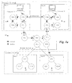
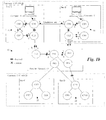
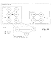
- Figures 1a through 1c illustrate a Customer VLAN using a backdoor connection
- Figure 2a illustrates a flow chart of a first embodiment of a routine executed by a provider edge bridge for detecting a topology change affecting paths through the backdoor connection;
- Figure 2b illustrates a flow chart of a second embodiment of a routine executed by a provider edge bridge for detecting a topology change affecting paths through the backdoor connection;
- Figures 3a through 3c illustrate a first topology of a Customer VLAN using multi-ported connections to the provider network
- Figure 4 illustrates a flow chart of a first embodiment of a routine executed by a provider edge bridge for detecting a topology change affecting paths through the multi-homed connection;
- Figure 5 illustrates a second topology of a Customer VLAN using multi-ported connections to the provider network
- Figure 6 illustrates a flow chart of a second embodiment of a routine executed by a provider edge bridge for detecting a topology change affecting paths through the multi-homed connection
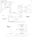
- Figure 7 illustrates a third topology of a Customer VLAN using multi-ported connections to the provider network
- Figure 8 illustrates a flow chart of a third embodiment of a routine executed by a provider edge bridge for detecting a topology change affecting paths through the multi-homed connection
- Figure 9 illustrates a block diagram of a bridge.
- Figures 1a and 1b illustrate a metropolitan area network 10 where a first customer, Customer 1, has two sites, Site A and Site B coupled through a provider network 12.
- Provider network 12 couples the LAN 14 of Site A with the LAN 16 of Site B to create a Customer VLAN 18.
- a second customer, Customer 2 has two sites, Site C and Site D coupled through the provider network 12.
- Provider network 12 couples the LAN 20 of Site C with the LAN 22 of Site D to create a Customer VLAN 24.
- the provider network 12 may provide coupling for a large number of customer VLANs, and customers may configure their LANs into different VLAN topologies.
- Provider network 12 can also be partitioned into multiple Provider VLANs.
- Each LAN is implemented using one or more bridges.
- a bridge in a customer LAN that connects to the provider network 12 is referred to as a "customer edge bridge” and is denoted in the drawings as “CE x ".
- a bridge in the provider network that connects to a customer edge bridge is referred to as a “provider edge bridge” and is denoted in the drawings as “PE x ".
- Other bridges are denoted as "CB x " for bridges in a customer LAN and "PB x " for bridges in a provider LAN.
- An end host (Computer X) resides on bridge CB1 of Site A and another end host (Computer Y) resides on bridge CB5 of Site B.
- a VLAN “segment” is defined as a network of customer bridges that are physically connected.
- a customer VLAN (or “C-VLAN”) is a collection of one or more physically separate VLAN segments that are logically connected through a provider network.
- a "dual-homed" (or “multi-homed") C-VLAN segment has one or more customer edge bridges (CEs) connecting to two or more distinct provider edge bridges (PEs).
- CEs customer edge bridges
- PEs provider edge bridges
- Site D has a dual-homed segment, since CE4 is connected to both PE3 and PE4.
- a single-homed segment has a single customer edge bridge connected to a single provider edge bridge.
- Site C has a single-homed segment, since CE3 is coupled only to PE3.
- Figure 1a shows the backdoor link between CB1 and CB6 as active. Normally, in typical configurations, the backdoor link is used for backup purposes and is normally blocked. The backdoor link could be used, for example, because of a broken CB6-CE2 link, which would prevent communication between Computers X and Y through the provider network 12.
- a computer with MAC address "X” is coupled to a port of bridge CB1 and a computer with MAC address "Y” is coupled to a port of bridge CB5.
- the forwarding port of MAC address "X" and "Y” is shown, as would be provided in a properly configured MAC address table.
- bridge PE1 receives an incoming frame addressed for "X”
- the frame is forwarded to the port connected to bridge CE1.
- bridge CB6 receives a frame addressed to "X”
- it is forwarded to bridge CB1 over the backdoor link.
- bridge CB6 receives a frame addressed to "Y”
- the frame is forwarded to the port connected to CB5.
- the backdoor link active no frames destined for "Y" from Site A will pass through the provider network 12, but frames from Site B, specifically frames received on bridges CE2 and CB4, may pass through the provider network 12 to get to the backdoor link.
- Topology changes in a customer LAN segments may or may not affect the entries in the MAC address table.
- Backdoor links and multi-homed LAN segments in general, may pose problems because they can create loops together with the provider network and, therefore, need to be configured carefully.
- FIG. 1b illustrates a topology change that will affect the MAC address tables of the bridges in Site A, but does not affect the MAC address table in any of the provider bridges.
- the CB2-CB3 link is activated and the CE1-CB1 link is blocked.
- TCNs will be generated accordingly within the Customer VLAN 18 to indicate that changes have been made to the topology.
- TCNs are generated as a BPDU (Bridge Protocol Data Unit); if the TCN flag is set in a BDPU, it is interpreted as a TCN.
- the MAC address tables for CE1 and CB2 must be changed in response to these TCNs, but the forwarding address in the provider bridges remain valid with regard to addresses X and Y. Therefore, unlearning address in the provider domain due these TCNs would be wasteful.
- Figure 1c shows a topology change that would affect the MAC address tables in the provider bridges.
- the broken CE2-CB6 link is repaired, and the spanning tree software blocks the backdoor link accordingly.
- the provider bridges will begin receiving frames for address Y on ports which previously were used to forward frames destined for address Y. Therefore, in response to the TCNs generated for this topology change, the provider bridges will need to unlearn and relearn the forwarding addresses.
- FIG. 2a illustrates a flow chart of a first embodiment of software implemented in the provider edge bridges for efficiently processing customer TCNs generated by the C-VLAN spanning tree.
- the PE receives a customer BDPU with the TCN flag set.
- the PE starts a timer in step 32.
- the PE monitors the MAC addresses of incoming frames from end hosts to determine whether the MAC addresses indicate a topology change in the customer VLAN that will require an unlearning operation in MAC address tables of the provider domain.
- the PE checks the MAC address in each incoming frame (step 38) and determines whether the MAC address is detected in a port that contradicts the information in the MAC address table (e.g., a MAC address for an end host previously seen on a customer facing port is now seen on a provider facing port). If so, then the PE initiates unlearning procedures (such as generating an unlearn message in the provider domain, as shown, or setting a bit on a message snooped by other bridges), wherein all of the bridges in the provider domain participating in this customer VLAN are flushed in step 40.
- unlearning procedures such as generating an unlearn message in the provider domain, as shown, or setting a bit on a message snooped by other bridges
- Step 38 If the incoming MAC address does not contradict information in the MAC address table in step 38, but the PE determines it is a new address (i.e., not in the PE's MAC address table), then the new address is written to a new address file in step 44. Steps 38-44 are repeated all frames received for the duration of the timer. When the timer expires in step 36, if the new address file has a number of entries that exceeds a predetermined threshold in step 46, then an unlearn message is generated in step 48.
- the flowchart of Figure 2a determines whether a TCN was generated for a topology change in the customer domain that may require unlearning/relearning operations in the provider domain, by checking for contradictory MAC address or new MAC addresses. However, receiving a new MAC address does not conclusively mean that the new address was received due to the topology change indicated by the received TCN. A new MAC address could also indicate that a MAC address was not previously active. Thus, an unlearning operation could be unnecessary.
- an incoming TCN in step 50 initiates a timer in step 52.
- a contradiction between the MAC address of the incoming frame and the PE's MAC address table (step 58) results in the initiation of an unlearn message to unlearn addresses in the provider domain (step 60).
- the MAC address of the incoming frame is not contradictory in step 58, but is a new address in step 62, it is stored in a new address file in step 64. Steps 58-64 are repeated until the timer expires in step 56. Once the timer expires, the new address file of the PE is sent to other PEs in step 66 to determine whether any of the new address in the file are ones that have been previously learned by the other PEs.
- step 70 If the PE received any positive replies from other PEs (i.e., replies indicating that one or more of the addresses in the new address file were previously learned), an unlearn message is generated in step 70. Otherwise, the monitoring is finished in step 72, and it is assumed that the TCN did not involve a backdoor in the customer VLAN topology.
- Querying PEs can be realized in several ways. One way would be to use an unreliable broadcast for a few times and to wait for replies for a period of time. If no replies are received during this period, the PE can trigger unlearning in the provider domain. Alternatively, a reliable transportation mechanism can be used with the other PEs, with acknowledgements between the querying PE and the other PEs.
- FIG. 3a through 8 illustrate operation of the PEs for various multi-homed topologies. While the examples are given with regard to dual-homed topologies, the methods described herein will work with three or more distinct connections to the provider network 12 as well.
- Site A has a dual-homed connection to the provider network 12, since CE1 is linked to PE1 and CE2 is linked to PE2. To prevent loops, the CE1-CB1 and CB1-CB2 links are blocked by the tree spanning software.
- Figure 3b a scenario is shown where a failure at the CE2-CB2 link causes the spanning tree software to reactivate the CE1-CB1 link.
- the TCNs are generated for this topology change, it is necessary for PE1 to be snooping the TCN such that an unlearning message can be sent to bridges in the provider domain.
- FIG. 4 illustrates a flow chart for a method of selectively snooping TCNs when a PE is aware that only one of multiple CEs will be active (i.e., only one CE is passing frames to/from end hosts) at any one time.
- a customer TCN is received in step 80, if the TCN is received through a blocked CE in block 82, then it starts unlearning in the provider domain in step 84. On the other hand, if the customer TCN is not received through the blocked CE, then it is passed through the provider network 12 without generating an unlearn command in step 86.
- Figure 5 illustrates an example of a dual-homed network where both CEs are active, with a blocked CB2-CE1 connection.
- both the CE1-PE1 and CE2-PE2 are single-homed, and TCNs received by the PEs can be passed through the provider network 12 without generating an unlearn command. If only the method of Figure 4 was applied, all TCNs from CE1 would be generate an unlearn command, because it is coupled to a blocked link (CB2-CE1). In fact, only TCNs related to the reactivation of the blocked CB2-CE1 link need to be snooped; all others can be passed without initiating unlearning in the provider domain.
- Figure 6 illustrates an example of an alternative method.
- an active CE with a blocked connection is responsible for setting a flag bit (a "snooping bit") in a BDPU, indicating whether the TCN is due to a change in status of the blocked link.
- This flagging need only happen at the CE and, therefore, existing bridges need not generally support it.
- step 90 a customer TCN is received by the PE.
- step 92 if the snooping bit is set, indicating that the blocked link is affected by the TCN, then the TCN initiates an unlearn command in step 94. Otherwise, the TCN is passed without generating an unlearn command in step 96.
- Figure 7 illustrates another dual-homed topology, where a single CE is linked to two PEs. In this case, one of the links between the CE and the two PEs will always be blocked. As shown, the CE1-PE1 link is blocked and the CE1-PE2 link is active. A failure in the CE1-PE2 link could cause the CE1-PE1 link to be reactivated; the TCNs for such a topology change should initiate unlearning in the provider domain, while other TCNs should be ignored.
- the snooping bit can be set by the CE to indicate which TCNs should initiate unlearning in the provider domain.
- the CE could set the snooping bit whenever the TCN is locally generated.
- FIG 8 illustrates a flow chart for dealing with TCNs from the topology of Figure 7.
- a TCN is received from a CE by a PE. If the snooping bit is set in step 102, then the TCN is initiates unlearning in the provider domain in step 104. Otherwise, the TCN is passed without unlearning in step 106.
- bits 2-7 of the fifth octet (the "flags" field) of the BDPU are unused (bits 1 and 8 are used) for an STP (spanning tree protocol) BDPU and the eighth bit of the fifth octet is unused in an RSTP (rapid spanning tree protocol) BDPU.
- the methods described above can greatly reduce the amount of unlearning and relearning in the provider bridges. Thus, they can greatly reduce the broadcasting storms that are seen in the provider domain due to customer TCNs triggering unlearning in the provider domain.
- FIG. 9 illustrates a basic block diagram of a edge bridge 110, which could be used for a CE or a PE.
- Edge bridge 110 includes a processor 102, which can be a general purpose processor, operating system software 104, and switching circuitry 106, typically implemented in an ASIC or a gate array.
- the processor stores relationships between its ports and end host addresses in a MAC address table (or forwarding database) 108.
- Operations such as checking snooping bits or TCN flags are preferably performed in the switching circuitry, which is high-speed, while other actions such as starting counters and generating messages are preferable performed in the processor 102 under control of the operating system software 104, which is easily modified.
Landscapes
- Engineering & Computer Science (AREA)
- Computer Networks & Wireless Communication (AREA)
- Signal Processing (AREA)
- Data Exchanges In Wide-Area Networks (AREA)
- Small-Scale Networks (AREA)
- Management, Administration, Business Operations System, And Electronic Commerce (AREA)
- Financial Or Insurance-Related Operations Such As Payment And Settlement (AREA)
- Information Transfer Between Computers (AREA)
Abstract
Description
Claims (10)
- A method for communication between two or more customer local area network (LAN) segments through a provider network, with each customer LAN segment including a customer edge bridge, and where the provider network has one or more provider edge bridges coupled to the customer edge bridges, comprising the steps of:in the provider edge bridges coupled to a customer LAN segment:receiving topology change notifications (TCNs) from the customer network;in response to receiving a TCN, monitoring end host addresses in data units received from the customer network for a predetermined time period;flushing an address memory file associating end host addresses with ports of the provider edge bridge in response to detecting an end host address indicating that a topology change has occurred in one or more of the customer LAN segments affecting paths of data units through the provider network.
- The method of claim 1 wherein said flushing step comprises the step of flushing the address memory file if the end host address of a data unit received in the predetermined time period is in conflict with information in the memory address file.
- The method of claim 1 wherein said flushing step comprises the step of flushing the address memory file if a predetermined number of end host addresses of data units received in the predetermined time period is not found in the address memory file.
- The method of claim 3 wherein said flushing step comprises the step of flushing the address memory file if the end host address of a data unit received in the predetermined time period is not found in the address memory file and if the end host address is found an address memory file of another bridge in the provider network.
- The method of claim 4 and further comprising the step of storing a list of end host addresses that are received during the predetermined time period and are not found in the address memory file.
- A provider edge bridge of a provider network for providing communication with one or more customer edge bridges of customer local area network (LAN) segments, comprising:processing circuitry for:receiving topology change notifications (TCNs) from the oen or more customer bridges;in response to receiving a TCN, monitoring end host addresses in data units received from the one or more customer bridges for a predetermined time period;flushing an address memory file associating end host addresses with ports of the provider edge bridge if a data unit received in the predetermined time period has a end host address indicating that a topology change has occurred in one or more of the customer LAN segments affecting paths of data units through the provider network.
- The provider edge bridge of claim 6 wherein said processor flushes the address memory file by flushing the address memory file if the end host address of a data unit received in the predetermined time period is in conflict with information in the memory address file.
- The provider edge bridge of claim 6 wherein said processor flushes the address memory file by flushing the address memory file if a predetermined number of end host addresses of data units received in the predetermined time period are not found in the address memory file.
- The provider edge bridge of claim 8 wherein said processor flushes the address memory file by flushing the address memory file if the end host address of a data unit received in the predetermined time period is not found in the address memory file and if the end host address is found an address memory file of another bridge in the provider network.
- The provider edge bridge of claim 9 and further including a memory for storing a list of end host addresses that are received during the predetermined time period and are not found in the address memory file.
Applications Claiming Priority (4)
| Application Number | Priority Date | Filing Date | Title |
|---|---|---|---|
| US737219 | 1976-11-04 | ||
| US45145203P | 2003-03-03 | 2003-03-03 | |
| US451452P | 2003-03-03 | ||
| US10/737,219 US8031630B2 (en) | 2003-03-03 | 2003-12-16 | Method and apparatus for updating provider domain due to customer TCNs |
Publications (3)
| Publication Number | Publication Date |
|---|---|
| EP1455510A2 true EP1455510A2 (en) | 2004-09-08 |
| EP1455510A3 EP1455510A3 (en) | 2006-02-01 |
| EP1455510B1 EP1455510B1 (en) | 2008-04-02 |
Family
ID=32830037
Family Applications (1)
| Application Number | Title | Priority Date | Filing Date |
|---|---|---|---|
| EP04004177A Expired - Lifetime EP1455510B1 (en) | 2003-03-03 | 2004-02-25 | Method and apparatus for updating provider domain by customer topology change notifications |
Country Status (4)
| Country | Link |
|---|---|
| US (1) | US8031630B2 (en) |
| EP (1) | EP1455510B1 (en) |
| AT (1) | ATE391373T1 (en) |
| DE (1) | DE602004012788T2 (en) |
Cited By (3)
| Publication number | Priority date | Publication date | Assignee | Title |
|---|---|---|---|---|
| WO2010048698A1 (en) * | 2008-10-28 | 2010-05-06 | Nortel Networks Limited | Provider link state bridging (plsb) computation method |
| WO2010066300A1 (en) * | 2008-12-11 | 2010-06-17 | Telefonaktiebolaget Lm Ericsson (Publ) | Communications network |
| EP2605452A4 (en) * | 2011-05-10 | 2014-06-18 | Univ De Alcalá | METHOD FOR REPAIRING DATA FRAME PATHS AND NETWORK BRIDGE |
Families Citing this family (11)
| Publication number | Priority date | Publication date | Assignee | Title |
|---|---|---|---|---|
| US7525974B2 (en) * | 2003-11-10 | 2009-04-28 | Nortel Networks Limited | Method and apparatus for capability based addressing in a communications network |
| US7953089B1 (en) * | 2006-05-16 | 2011-05-31 | Cisco Technology, Inc. | Systems and methods for multicast switching in a private VLAN |
| CN101483558B (en) * | 2008-01-10 | 2012-07-04 | 华为技术有限公司 | Method, system and apparatus for packet switching network access by network appliance |
| IL192140A0 (en) * | 2008-06-12 | 2009-02-11 | Ethos Networks Ltd | Method and system for transparent lan services in a packet network |
| US8625410B2 (en) * | 2009-05-11 | 2014-01-07 | Ciena Corporation | Dual homed E-spring protection for network domain interworking |
| CN102148811B (en) * | 2010-02-10 | 2015-01-28 | 中兴通讯股份有限公司 | Flexible QinQ realization method and device |
| CA2790247A1 (en) * | 2010-02-19 | 2011-08-25 | David Berechya | Method and device for conveying oam messages across an inter-carrier network |
| US8873431B1 (en) | 2010-04-08 | 2014-10-28 | Adtran, Inc. | Communications system and method for maintaining topology in a VLAN environment |
| US8804570B1 (en) * | 2010-12-17 | 2014-08-12 | Juniper Networks, Inc. | Propagating LDP MAC flush as TCN |
| CN104303462B (en) * | 2012-07-30 | 2017-10-31 | 慧与发展有限责任合伙企业 | Provider's bridge coil communication system and method |
| CN104601461B (en) * | 2013-10-30 | 2018-02-09 | 新华三技术有限公司 | Message forwarding method and device in a kind of Longitudinal Intelligence resilient infrastructure system |
Family Cites Families (8)
| Publication number | Priority date | Publication date | Assignee | Title |
|---|---|---|---|---|
| US5590120A (en) * | 1995-10-31 | 1996-12-31 | Cabletron Systems, Inc. | Port-link configuration tracking method and apparatus |
| US6032194A (en) * | 1997-12-24 | 2000-02-29 | Cisco Technology, Inc. | Method and apparatus for rapidly reconfiguring computer networks |
| US6330229B1 (en) | 1998-11-09 | 2001-12-11 | 3Com Corporation | Spanning tree with rapid forwarding database updates |
| US6937576B1 (en) * | 2000-10-17 | 2005-08-30 | Cisco Technology, Inc. | Multiple instance spanning tree protocol |
| US6973023B1 (en) * | 2000-12-30 | 2005-12-06 | Cisco Technology, Inc. | Method for routing information over a network employing centralized control |
| US7277399B1 (en) * | 2002-04-08 | 2007-10-02 | Cisco Technology, Inc. | Hardware-based route cache using prefix length |
| US20030235157A1 (en) * | 2002-06-21 | 2003-12-25 | International Business Machines Corporation | Method and structure for an autoconfiguration topology calculation |
| US20040151129A1 (en) * | 2003-01-31 | 2004-08-05 | Gyula Kun-Szabo | Controller for controlling routers |
-
2003
- 2003-12-16 US US10/737,219 patent/US8031630B2/en not_active Expired - Fee Related
-
2004
- 2004-02-25 EP EP04004177A patent/EP1455510B1/en not_active Expired - Lifetime
- 2004-02-25 AT AT04004177T patent/ATE391373T1/en not_active IP Right Cessation
- 2004-02-25 DE DE602004012788T patent/DE602004012788T2/en not_active Expired - Lifetime
Cited By (7)
| Publication number | Priority date | Publication date | Assignee | Title |
|---|---|---|---|---|
| WO2010048698A1 (en) * | 2008-10-28 | 2010-05-06 | Nortel Networks Limited | Provider link state bridging (plsb) computation method |
| US8005016B2 (en) | 2008-10-28 | 2011-08-23 | Nortel Networks Limited | Provider link state bridging (PLSB) computation method |
| US8605627B2 (en) | 2008-10-28 | 2013-12-10 | Rockstar Consortium Us Lp | Provider link state bridging (PLSB) computation method |
| CN102197625B (en) * | 2008-10-28 | 2014-04-02 | 北方电讯网络有限公司 | Provider link state bridging (PLSB) computation method |
| WO2010066300A1 (en) * | 2008-12-11 | 2010-06-17 | Telefonaktiebolaget Lm Ericsson (Publ) | Communications network |
| US8619632B2 (en) | 2008-12-11 | 2013-12-31 | Telefonaktiebolaget L M Ericsson (Publ) | Communications network with enhanced notification for topology change |
| EP2605452A4 (en) * | 2011-05-10 | 2014-06-18 | Univ De Alcalá | METHOD FOR REPAIRING DATA FRAME PATHS AND NETWORK BRIDGE |
Also Published As
| Publication number | Publication date |
|---|---|
| EP1455510A3 (en) | 2006-02-01 |
| ATE391373T1 (en) | 2008-04-15 |
| DE602004012788D1 (en) | 2008-05-15 |
| US20040174828A1 (en) | 2004-09-09 |
| DE602004012788T2 (en) | 2009-04-09 |
| EP1455510B1 (en) | 2008-04-02 |
| US8031630B2 (en) | 2011-10-04 |
Similar Documents
| Publication | Publication Date | Title |
|---|---|---|
| EP2560325B1 (en) | Method, system and apparatus for managing addresses in ethernet ring network | |
| US6917986B2 (en) | Fast failure protection using redundant network edge ports | |
| US8565069B2 (en) | Method of shrinking a data loss window in a packet network device | |
| US7366191B2 (en) | Mesh network bridges making operable spanning tree protocol and line fault backup protocol in optimized forwarding environment | |
| EP1455510A2 (en) | Method and apparatus for updating provider domain due to customer TCNS | |
| US6857027B1 (en) | Intelligent network topology and configuration verification using a method of loop detection | |
| AU2007247560B2 (en) | Automatic packet protection forwarding to an mpls network by a dual-homed ethernet bridge | |
| US7782763B2 (en) | Failure protection in a provider backbone bridge network using forced MAC flushing | |
| EP2274878B1 (en) | Reducing traffic loss in an eaps system | |
| US11863350B2 (en) | Fast convergence of E-Tree with a dual homed root node | |
| US20090274153A1 (en) | System and method for implementation of layer 2 redundancy protocols across multiple networks | |
| US7965623B1 (en) | LAN switch with rapid fault recovery | |
| EP3641241A1 (en) | Node protection for bum traffic for multi-homed node failure | |
| KR20080089285A (en) | How to Transfer Protection in an Ethernet Ring Network | |
| CN101984591B (en) | Service convergence method and system in transport-multiprotocol label switching network | |
| WO2011121673A1 (en) | Network relay node device, network relay method, program, and network system | |
| US7995499B2 (en) | Minimizing spanning-tree protocol event processing and flooding in distribution networks | |
| JPWO2007086539A1 (en) | Network node, frame transfer program, and frame transfer method | |
| CN101114989A (en) | A processing method for routing of three-layer Ethernet switches directly connected to hosts | |
| US9509595B2 (en) | Method for processing subnet route and message forwarding equipment | |
| JP3978099B2 (en) | Communication network system management method and network relay device |
Legal Events
| Date | Code | Title | Description |
|---|---|---|---|
| PUAI | Public reference made under article 153(3) epc to a published international application that has entered the european phase |
Free format text: ORIGINAL CODE: 0009012 |
|
| AK | Designated contracting states |
Kind code of ref document: A2 Designated state(s): AT BE BG CH CY CZ DE DK EE ES FI FR GB GR HU IE IT LI LU MC NL PT RO SE SI SK TR |
|
| AX | Request for extension of the european patent |
Extension state: AL LT LV MK |
|
| RIN1 | Information on inventor provided before grant (corrected) |
Inventor name: ROSE, LAURENCE Inventor name: CARTIER, JEAN-FRANCOIS Inventor name: CHIRUVOLU, GIRISH Inventor name: GOODWIN, MICHELE L. Inventor name: TANCEVSKI, LJUBISA Inventor name: ELIE-DIT-COSAQUE, DAVID Inventor name: ROUYER, JESSY |
|
| RTI1 | Title (correction) |
Free format text: METHOD AND APPARATUS FOR UPDATING PROVIDER DOMAIN BY CUSTOMER TOPOLOGY CHANGE NOTIFICATIONS |
|
| RIN1 | Information on inventor provided before grant (corrected) |
Inventor name: TANCEVSKI, LJUBISA Inventor name: ROUYER, JESSY V. Inventor name: ROSE, LAURENCE Inventor name: GOODWIN, MICHELE L. Inventor name: CHIRUVOLU, GIRISH Inventor name: ELIE-DIT-COSAQUE, DAVID Inventor name: CARTIER, JEAN-FRANCOIS |
|
| PUAL | Search report despatched |
Free format text: ORIGINAL CODE: 0009013 |
|
| AK | Designated contracting states |
Kind code of ref document: A3 Designated state(s): AT BE BG CH CY CZ DE DK EE ES FI FR GB GR HU IE IT LI LU MC NL PT RO SE SI SK TR |
|
| AX | Request for extension of the european patent |
Extension state: AL LT LV MK |
|
| RIC1 | Information provided on ipc code assigned before grant |
Ipc: H04L 12/46 20060101AFI20051209BHEP |
|
| RIN1 | Information on inventor provided before grant (corrected) |
Inventor name: CARTIER, JEAN-FRANCOIS Inventor name: ROSE, LAURENCE Inventor name: GOODWIN, MICHELE L. Inventor name: ROUYER, JESSY V. Inventor name: ELIE-DIT-COSAQUE, DAVID Inventor name: TANCEVSKI, LJUBISA Inventor name: CHIRUVOLU, GIRISH |
|
| 17P | Request for examination filed |
Effective date: 20060731 |
|
| 17Q | First examination report despatched |
Effective date: 20060829 |
|
| AKX | Designation fees paid |
Designated state(s): AT BE BG CH CY CZ DE DK EE ES FI FR GB GR HU IE IT LI LU MC NL PT RO SE SI SK TR |
|
| RAP1 | Party data changed (applicant data changed or rights of an application transferred) |
Owner name: ALCATEL LUCENT |
|
| RIN1 | Information on inventor provided before grant (corrected) |
Inventor name: ROSE, LAURENCE Inventor name: TANCEVSKI, LJUBISA Inventor name: CARTIER, JEAN-FRANCOIS Inventor name: ROUYER, JESSY V. Inventor name: GOODWIN, MICHELE L. Inventor name: ELIE-DIT-COSAQUE, DAVID Inventor name: CHIRUVOLU, GIRISH |
|
| GRAP | Despatch of communication of intention to grant a patent |
Free format text: ORIGINAL CODE: EPIDOSNIGR1 |
|
| GRAS | Grant fee paid |
Free format text: ORIGINAL CODE: EPIDOSNIGR3 |
|
| GRAA | (expected) grant |
Free format text: ORIGINAL CODE: 0009210 |
|
| AK | Designated contracting states |
Kind code of ref document: B1 Designated state(s): AT BE BG CH CY CZ DE DK EE ES FI FR GB GR HU IE IT LI LU MC NL PT RO SE SI SK TR |
|
| REG | Reference to a national code |
Ref country code: GB Ref legal event code: FG4D |
|
| REG | Reference to a national code |
Ref country code: IE Ref legal event code: FG4D Ref country code: CH Ref legal event code: EP |
|
| REF | Corresponds to: |
Ref document number: 602004012788 Country of ref document: DE Date of ref document: 20080515 Kind code of ref document: P |
|
| PG25 | Lapsed in a contracting state [announced via postgrant information from national office to epo] |
Ref country code: SI Free format text: LAPSE BECAUSE OF FAILURE TO SUBMIT A TRANSLATION OF THE DESCRIPTION OR TO PAY THE FEE WITHIN THE PRESCRIBED TIME-LIMIT Effective date: 20080402 |
|
| NLV1 | Nl: lapsed or annulled due to failure to fulfill the requirements of art. 29p and 29m of the patents act | ||
| PG25 | Lapsed in a contracting state [announced via postgrant information from national office to epo] |
Ref country code: PT Free format text: LAPSE BECAUSE OF FAILURE TO SUBMIT A TRANSLATION OF THE DESCRIPTION OR TO PAY THE FEE WITHIN THE PRESCRIBED TIME-LIMIT Effective date: 20080903 Ref country code: BG Free format text: LAPSE BECAUSE OF FAILURE TO SUBMIT A TRANSLATION OF THE DESCRIPTION OR TO PAY THE FEE WITHIN THE PRESCRIBED TIME-LIMIT Effective date: 20080702 Ref country code: NL Free format text: LAPSE BECAUSE OF FAILURE TO SUBMIT A TRANSLATION OF THE DESCRIPTION OR TO PAY THE FEE WITHIN THE PRESCRIBED TIME-LIMIT Effective date: 20080402 Ref country code: FI Free format text: LAPSE BECAUSE OF FAILURE TO SUBMIT A TRANSLATION OF THE DESCRIPTION OR TO PAY THE FEE WITHIN THE PRESCRIBED TIME-LIMIT Effective date: 20080402 Ref country code: ES Free format text: LAPSE BECAUSE OF FAILURE TO SUBMIT A TRANSLATION OF THE DESCRIPTION OR TO PAY THE FEE WITHIN THE PRESCRIBED TIME-LIMIT Effective date: 20080713 |
|
| PG25 | Lapsed in a contracting state [announced via postgrant information from national office to epo] |
Ref country code: AT Free format text: LAPSE BECAUSE OF FAILURE TO SUBMIT A TRANSLATION OF THE DESCRIPTION OR TO PAY THE FEE WITHIN THE PRESCRIBED TIME-LIMIT Effective date: 20080402 |
|
| ET | Fr: translation filed | ||
| PG25 | Lapsed in a contracting state [announced via postgrant information from national office to epo] |
Ref country code: DK Free format text: LAPSE BECAUSE OF FAILURE TO SUBMIT A TRANSLATION OF THE DESCRIPTION OR TO PAY THE FEE WITHIN THE PRESCRIBED TIME-LIMIT Effective date: 20080402 Ref country code: SE Free format text: LAPSE BECAUSE OF FAILURE TO SUBMIT A TRANSLATION OF THE DESCRIPTION OR TO PAY THE FEE WITHIN THE PRESCRIBED TIME-LIMIT Effective date: 20080702 Ref country code: CZ Free format text: LAPSE BECAUSE OF FAILURE TO SUBMIT A TRANSLATION OF THE DESCRIPTION OR TO PAY THE FEE WITHIN THE PRESCRIBED TIME-LIMIT Effective date: 20080402 |
|
| PLBE | No opposition filed within time limit |
Free format text: ORIGINAL CODE: 0009261 |
|
| STAA | Information on the status of an ep patent application or granted ep patent |
Free format text: STATUS: NO OPPOSITION FILED WITHIN TIME LIMIT |
|
| PG25 | Lapsed in a contracting state [announced via postgrant information from national office to epo] |
Ref country code: RO Free format text: LAPSE BECAUSE OF FAILURE TO SUBMIT A TRANSLATION OF THE DESCRIPTION OR TO PAY THE FEE WITHIN THE PRESCRIBED TIME-LIMIT Effective date: 20080402 Ref country code: SK Free format text: LAPSE BECAUSE OF FAILURE TO SUBMIT A TRANSLATION OF THE DESCRIPTION OR TO PAY THE FEE WITHIN THE PRESCRIBED TIME-LIMIT Effective date: 20080402 Ref country code: BE Free format text: LAPSE BECAUSE OF FAILURE TO SUBMIT A TRANSLATION OF THE DESCRIPTION OR TO PAY THE FEE WITHIN THE PRESCRIBED TIME-LIMIT Effective date: 20080402 |
|
| 26N | No opposition filed |
Effective date: 20090106 |
|
| PG25 | Lapsed in a contracting state [announced via postgrant information from national office to epo] |
Ref country code: EE Free format text: LAPSE BECAUSE OF FAILURE TO SUBMIT A TRANSLATION OF THE DESCRIPTION OR TO PAY THE FEE WITHIN THE PRESCRIBED TIME-LIMIT Effective date: 20080402 |
|
| PG25 | Lapsed in a contracting state [announced via postgrant information from national office to epo] |
Ref country code: IT Free format text: LAPSE BECAUSE OF FAILURE TO SUBMIT A TRANSLATION OF THE DESCRIPTION OR TO PAY THE FEE WITHIN THE PRESCRIBED TIME-LIMIT Effective date: 20080402 |
|
| PG25 | Lapsed in a contracting state [announced via postgrant information from national office to epo] |
Ref country code: CY Free format text: LAPSE BECAUSE OF FAILURE TO SUBMIT A TRANSLATION OF THE DESCRIPTION OR TO PAY THE FEE WITHIN THE PRESCRIBED TIME-LIMIT Effective date: 20080402 Ref country code: MC Free format text: LAPSE BECAUSE OF NON-PAYMENT OF DUE FEES Effective date: 20090228 |
|
| REG | Reference to a national code |
Ref country code: CH Ref legal event code: PL |
|
| PG25 | Lapsed in a contracting state [announced via postgrant information from national office to epo] |
Ref country code: CH Free format text: LAPSE BECAUSE OF NON-PAYMENT OF DUE FEES Effective date: 20090228 Ref country code: LI Free format text: LAPSE BECAUSE OF NON-PAYMENT OF DUE FEES Effective date: 20090228 |
|
| PG25 | Lapsed in a contracting state [announced via postgrant information from national office to epo] |
Ref country code: IE Free format text: LAPSE BECAUSE OF NON-PAYMENT OF DUE FEES Effective date: 20090225 |
|
| PG25 | Lapsed in a contracting state [announced via postgrant information from national office to epo] |
Ref country code: GR Free format text: LAPSE BECAUSE OF FAILURE TO SUBMIT A TRANSLATION OF THE DESCRIPTION OR TO PAY THE FEE WITHIN THE PRESCRIBED TIME-LIMIT Effective date: 20080703 |
|
| PG25 | Lapsed in a contracting state [announced via postgrant information from national office to epo] |
Ref country code: LU Free format text: LAPSE BECAUSE OF NON-PAYMENT OF DUE FEES Effective date: 20090225 |
|
| PG25 | Lapsed in a contracting state [announced via postgrant information from national office to epo] |
Ref country code: HU Free format text: LAPSE BECAUSE OF FAILURE TO SUBMIT A TRANSLATION OF THE DESCRIPTION OR TO PAY THE FEE WITHIN THE PRESCRIBED TIME-LIMIT Effective date: 20081003 |
|
| PG25 | Lapsed in a contracting state [announced via postgrant information from national office to epo] |
Ref country code: TR Free format text: LAPSE BECAUSE OF FAILURE TO SUBMIT A TRANSLATION OF THE DESCRIPTION OR TO PAY THE FEE WITHIN THE PRESCRIBED TIME-LIMIT Effective date: 20080402 |
|
| REG | Reference to a national code |
Ref country code: GB Ref legal event code: 732E Free format text: REGISTERED BETWEEN 20130926 AND 20131002 |
|
| REG | Reference to a national code |
Ref country code: FR Ref legal event code: GC Effective date: 20131018 |
|
| REG | Reference to a national code |
Ref country code: FR Ref legal event code: RG Effective date: 20141016 |
|
| REG | Reference to a national code |
Ref country code: FR Ref legal event code: PLFP Year of fee payment: 12 |
|
| REG | Reference to a national code |
Ref country code: FR Ref legal event code: CA Effective date: 20150521 |
|
| REG | Reference to a national code |
Ref country code: FR Ref legal event code: CA Effective date: 20150521 |
|
| REG | Reference to a national code |
Ref country code: FR Ref legal event code: PLFP Year of fee payment: 13 |
|
| REG | Reference to a national code |
Ref country code: FR Ref legal event code: PLFP Year of fee payment: 14 |
|
| REG | Reference to a national code |
Ref country code: FR Ref legal event code: PLFP Year of fee payment: 15 |
|
| PGFP | Annual fee paid to national office [announced via postgrant information from national office to epo] |
Ref country code: DE Payment date: 20190212 Year of fee payment: 16 Ref country code: GB Payment date: 20190220 Year of fee payment: 16 Ref country code: FR Payment date: 20190111 Year of fee payment: 16 |
|
| REG | Reference to a national code |
Ref country code: DE Ref legal event code: R119 Ref document number: 602004012788 Country of ref document: DE |
|
| GBPC | Gb: european patent ceased through non-payment of renewal fee |
Effective date: 20200225 |
|
| PG25 | Lapsed in a contracting state [announced via postgrant information from national office to epo] |
Ref country code: FR Free format text: LAPSE BECAUSE OF NON-PAYMENT OF DUE FEES Effective date: 20200229 Ref country code: DE Free format text: LAPSE BECAUSE OF NON-PAYMENT OF DUE FEES Effective date: 20200901 Ref country code: GB Free format text: LAPSE BECAUSE OF NON-PAYMENT OF DUE FEES Effective date: 20200225 |