EP1455473A2 - Clock Synchronisation over a Packet Network - Google Patents
Clock Synchronisation over a Packet Network Download PDFInfo
- Publication number
- EP1455473A2 EP1455473A2 EP04270001A EP04270001A EP1455473A2 EP 1455473 A2 EP1455473 A2 EP 1455473A2 EP 04270001 A EP04270001 A EP 04270001A EP 04270001 A EP04270001 A EP 04270001A EP 1455473 A2 EP1455473 A2 EP 1455473A2
- Authority
- EP
- European Patent Office
- Prior art keywords
- packet
- clock
- frequency
- minimum
- transit time
- Prior art date
- Legal status (The legal status is an assumption and is not a legal conclusion. Google has not performed a legal analysis and makes no representation as to the accuracy of the status listed.)
- Granted
Links
Images


Classifications
-
- H—ELECTRICITY
- H04—ELECTRIC COMMUNICATION TECHNIQUE
- H04J—MULTIPLEX COMMUNICATION
- H04J3/00—Time-division multiplex systems
- H04J3/02—Details
- H04J3/06—Synchronising arrangements
- H04J3/062—Synchronisation of signals having the same nominal but fluctuating bit rates, e.g. using buffers
- H04J3/0632—Synchronisation of packets and cells, e.g. transmission of voice via a packet network, circuit emulation service [CES]
-
- H—ELECTRICITY
- H04—ELECTRIC COMMUNICATION TECHNIQUE
- H04L—TRANSMISSION OF DIGITAL INFORMATION, e.g. TELEGRAPHIC COMMUNICATION
- H04L7/00—Arrangements for synchronising receiver with transmitter
-
- H—ELECTRICITY
- H04—ELECTRIC COMMUNICATION TECHNIQUE
- H04J—MULTIPLEX COMMUNICATION
- H04J3/00—Time-division multiplex systems
- H04J3/02—Details
- H04J3/06—Synchronising arrangements
- H04J3/0635—Clock or time synchronisation in a network
- H04J3/0638—Clock or time synchronisation among nodes; Internode synchronisation
- H04J3/0658—Clock or time synchronisation among packet nodes
- H04J3/0661—Clock or time synchronisation among packet nodes using timestamps
- H04J3/0664—Clock or time synchronisation among packet nodes using timestamps unidirectional timestamps
Definitions
- the present invention relates to clock synchronisation over a packet network.
- the invention is applicable in particular, though not necessarily, to the synchronisation of clocks associated with time division multiplexed transmission links interconnected by a packet network.
- Communication networks typically make use of one of two well established transmission mechanisms; circuit switched transfer and packet switched (or just packet) transfer. Older systems tend to use the former, and in the main use time division multiplexing to divide the time domain, for a given frequency band, into time slots of equal duration. Circuits are defined by grouping together identical slot positions in successive time frames. Packet networks typically do not allocate fixed resources to transmitters, but rather route packets of data on a best efforts basis, using destination address information contained in packet headers, and network switches and routers. Packet networks are becoming more popular amongst network operators as they often provide better performance, and are more cost effective to install and maintain, than equivalent circuit switched networks.
- TDM time division multiplexed
- FIG. 1 illustrates schematically a carrier network 1 which is a packet switched network such as an Ethernet, ATM, or IP network.
- the carrier network provides leased line services to interconnect first and second customer premises 2,3, both of which make use of TDM transmitters 4,5 to handle multiple information streams.
- the nature of these streams is unimportant, although they could for example be voice calls, videoconference calls, or data calls.
- the carrier network 1 In order to facilitate the interconnection of the TDM streams, the carrier network 1 must emulate appropriate TDM circuits.
- TDM links are synchronous circuits with a constant (transmission) bit rate governed by a service clock operating at some predefined frequency.
- a packet network there is no direct link between the frequency at which packets are sent from an ingress port and the frequency at which they arrive at an egress port.
- interface nodes 6,7 at the edges of the packet network must provide interworking between the TDM links and the packet network in such a way that the TDM link at the egress side is synchronised with the TDM link at the ingress side.
- the TDM service frequency ( f service ) at the customer premises on the ingress side must be exactly reproduced at the egress of the packet network ( f regen ).
- the consequence of any long-term mismatch in these frequencies will be that the queue at the egress of the packet network will either fill up or empty, depending upon on whether the regenerated clock ( f regen ) is slower or faster than the original clock ( f service ), causing loss of data and degradation of the service.
- the phase of the original clock ( f service ) is tracked by that of the regenerated clock ( f regen )
- the lag in frequency tracking will result in small but nonetheless undesirable changes to the operating level of the queue at the egress.
- Some reliable method for synchronising both the frequency and phase of the clock at the egress of a packet network to those of the clock at the TDM transmitted must be provided.
- One approach is to use some algorithm to recover the transmitting clock frequency and phase from timestamps incorporated into packets by the sender, taking into account the transmission delay over the packet network.
- an adaptive algorithm might be used. For example, some form of averaging might be employed to take into account variations in the transmission delay.
- ITU standard I.363.1 and ATM Forum standard af-vtoa-0078 explain the concept of an adaptive clock recovery mechanism in general terms.
- a method of synchronising first and second clocks coupled respectively to ingress and egress interfaces of a packet network where the first clock determines the bit rate of a constant bit rate stream arriving at the ingress interface and the second clock rate determines the bit rate of a constant bit rate stream sent from the egress interface, the method comprising calculating a minimum packet Transit Time over the network in each of successive time intervals, and varying the frequency of the second clock so as to maintain a constant value of the calculated minimum packet transit time and hence achieve both phase and frequency synchronisation of the first and second clocks.
- said minimum packet Transit Time is calculated using Local and Remote Timestamps which increase linearly at the first and second clock frequencies respectively or at multiples or sub-multiples thereof. More preferably, the method comprises calculating a packet Transit Time for each packet received at said egress, and identifying the minimum packet Transit Time within each time interval.
- the method comprises:
- the method comprises incorporating respective Remote Timestamps into packets at said ingress to the packet network, said step of determining a Remote Timestamp value for a packet at the egress comprising extracting the Remote Timestamp from the packet.
- said step of determining a Remote Timestamp for each packet comprises computing the Timestamp at the egress from the packet network.
- this step comprises maintaining a data counter at said egress, which counter records the data volume contained in the payloads of received packets, and using the value contained in said counter when a packet is received, as the Remote Timestamp for that packet.
- this step may comprise computing the Remote Timestamp using the packet payload size and packet sequence number.
- Said Local and Remote Timestamps may be counts representing numbers of bits fractional bits, multiples of bits, frames of the synchronous data streams, or may represent packet payload size.
- the frequency of the second clock may be adjusted using the difference between the most recently determined minimum Transit Time and the previously determined minimum Transit Time. Said difference is scaled by an appropriate factor and the result is added to or subtracted from the current second clock frequency.
- the frequency of the second clock may be adjusted in dependence upon the difference between the most recently determined minimum Transit Time and an offset value. Said difference is scaled by an appropriate factor and the result is added to or subtracted from the current second clock frequency, and said offset value is determined using a fill level of a buffer of the egress into which incoming packets are placed. The fill level is filtered to remove short term fluctuations, and the offset value is derived from the filtered result.
- the ingress to the packet network is coupled to a first time division multiplexed (TDM) link, the TDM link operating at said first clock frequency, with the egress from the packet network being coupled to a second TDM link operating at said second clock frequency.
- TDM time division multiplexed
- apparatus for synchronising first and second clocks coupled respectively to ingress and egress interfaces over a packet network, the apparatus comprising means for calculating a minimum packet Transit Time in each of successive time intervals, and means for varying the frequency of the second clock so as to track variations in the minimum packet Transit Time.
- the apparatus comprises:
- the rate of transmission of packets from the source or "ingress" interface 6 is isochronous and determined by a service frequency (f service ) provided for example by a suitable Oscillator 8.
- f service service frequency
- the rate of packet arrival at the destination interface 7 is perturbed by the intervening packet network. Packets will typically arrive in bursts separated by varying amounts of delay. The delay between successive packets and bursts will vary for example depending on the amount of traffic in the network. The characteristics of the network are non-deterministic, but over the long term the rate of arrival at the destination will equal the rate of departure from the source.
- a timestamp is placed into the header of each packet prior to transmission.
- This timestamp is referred to here as the "Remote Timestamp”, and is a running total of the bits received on the incoming TDM link since initialisation (wrap around of this count will occur to avoid counter overflow).
- the TDM output at the destination interface 7 is isochronous and determined by a second service frequency, referred to here as the "regeneration" frequency (f regen ). This is provided by a Digitally Controlled Oscillator (DCO) 9.
- the destination interface output is supplied from a Packet Delay Variation (PDV) buffer 10. If the buffer 10 has zero packets in it when the TDM output requires to transmit, an underrun will occur, which is undesirable. In order to minimise underrun events it is necessary to build up the PDV buffer 10 so that it contains sufficient packets to supply the TDM output for the majority of inter packet delays. However, the PDV buffer 10 cannot be made arbitrarily large because this directly increases the end to end latency which, in general, is required to be as low as possible, the maximum tolerable latency being dependent on the application. For example, voice requires lower latency than data.
- Transit Time (n) Remote Timestamp(n) - Local Timestamp(n) where n is a packet sequence number.
- Transit Time in this equation does not represent the actual time that the packet has taken to travel between the source and destination interfaces 6,7.
- the Transit Time will decrease if f service exceeds f regen , will increase if f regen exceeds f service , and will remain constant if these frequencies are identical. Therefore, variations in Transit Time values will be caused by relative offset and/or drift between the source and destination clock frequencies, and also by variation in the delay experienced by each packet as it passes through the packet network.
- the minimum delay should not vary to the same extent. Therefore identifying the minimum packet delay within each of successive time periods should give the required indication of drift between the source and destination clock frequencies, independent of changes in network loading. This is very important where such changes in loading occur at a relatively low frequency, for example a 24 hour cycle. Such low frequency variations may be indistinguishable from source clock frequency drift which must be followed by the clock recovery system.
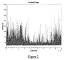
- Figure 2 shows the delays suffered by packets in a packet network measured over a 12-hour period.
- one measurement was made per second using the Unix "ping" command. It can be seen that the variation in the minimum delay is small (marked by the relatively straight bottom edge of the trace) in comparison to the variation in the instantaneous delay value. Also, the high density of the bottom edge shows that the minimum values occur fairly frequently.
- a Transit Time is calculated for every packet received at the destination interface. Over some given period referred to as the "clock control interval", e.g. 1 second, the minimum Transit Time is determined. The minimum Transit Time is reset for each new time period. Immediately after the expiry of a time period, a clock control algorithm will read the minimum Transit Time recorded for that period, determine the correction required to the destination interface clock frequency, and write the required frequency to the DCO of the destination interface.
- the clock control interval will generally be relatively large compared to the (transmission and arrival) intervals between packets so that the minimum Transit Time that the algorithm reads will be the minimum of a large set of Transit Time values.
- the constants G1 and G2 determine the frequency response of the system and are selected to track long term drift in f service but reject short-term variation due to packet delay variations.
- a further term may optionally be added to Equation (2). This makes use of an Offset constant which can be used during operation to adjust the operating point (i.e. fill level) of the PDV buffer to a new value. This may be desirable in order to cope with changing network conditions which cause the buffer to empty (or overflow).
- a filter function such as a first order filter, may be used to provide a filtered measurement of the PDV buffer fill level. The clock control algorithm can then be expanded to read the filtered level, and set the Offset accordingly.
- This system is robust in the presence of lost packets because the Remote and Local Timestamps of the next packet received following any lost packet(s) are unaffected by the loss.
- the lost packets merely represent a short term loss of resolution in the measurement. In a typical system there will be thousands of packets per second so that even a packet loss rate which is at or close to the maximum (i.e. a few percent) will have a negligible effect on the result.
- Figure 3 illustrates schematically the clock recovery process described above incorporated into the destination interface architecture.
- the clock recovery method described here provides a number of advantages over known methods. These include:
- Figure 4 illustrates such a scenario, plotting minimum Transit Time against time and where a step change occurs in the minimum Transit Time.
- the frequency f regen is not adjusted (i.e. it is maintained in a "holdover" state).
- the value TransitTarget in Equation (2) above is adjusted to the new minimum Transit Time. Phase locking then continues based around the new target point. This allows f regen to exit from the holdover state with minimal phase realignment.
- the least delayed packets may occur very infrequently so rejection of the timing from other packets is of utmost importance to allow a clock to be recovered with sufficient accuracy to meet the stringent phase requirements for the synchronous TDM circuit that is being replaced.
- a minimum Transit Time for a given interval (say of duration t 1 ) is validated against the minimum transit times determined in each of a sequence of previous intervals (also of duration t 1 ), as well as against the minimum Transit Time in a larger interval t 2 including each of those previous intervals and the present interval.
- This is illustrated in Figure 5.
- the minimum Transit Time from the most recent interval t 1 is selected, since this reduces lag in the control loop and provides greater stability for a given loop filter, or allows a faster response loop filter to be employed.
- an alternative minimum is used or the current minimum discarded.
- the threshold used to validate the Transit Time is reduced, so as to provide more precise information for use in the control of the clock f regen . This is illustrated in Figure 6.
- the threshold may also be increased if phase locking starts to fail. Hysteresis is used to avoid problems when changing ranges. It would also be possible to perform the validation criteria using a continuous scheme rather than using explicit ranges.
- the range currently being used also controls how the Transit Time is handled if it falls outside of the range.
- Transit Time (n) Remote Timestamp(n) - Local Timestamp(n) such that the least delayed packets will have a greater Transit Time than the most delayed packets.
- f regen is set to some predefined frequency. Over the first interval n , the minimum Transit Time is determined. After some further period has elapsed, e.g. 1 minute, the minimum Transit Time over interval m is determined. These values, together with the times of occurrence of the respective minimum Transit Times are used in equation (3) to determine the frequency offset in PPM. The frequency of the destination clock, f regen , is incremented or decremented accordingly.
- An improved offset may be obtained by compensating the Transit Time estimates (in intervals n and m ) using the initial offset estimate. New minimum Transit Times in these intervals are then determined and used to compute an improved frequency offset. This process may be repeated to improve the estimate still further.
- the quick synchronisation procedure described above may be used independently of the phase and frequency synchronisation procedure based upon equation (2), in systems where only frequency locking is required.
Landscapes
- Engineering & Computer Science (AREA)
- Computer Networks & Wireless Communication (AREA)
- Signal Processing (AREA)
- Multimedia (AREA)
- Computer Hardware Design (AREA)
- Data Exchanges In Wide-Area Networks (AREA)
- Synchronisation In Digital Transmission Systems (AREA)
- Use Of Switch Circuits For Exchanges And Methods Of Control Of Multiplex Exchanges (AREA)
- Telephonic Communication Services (AREA)
Abstract
Description
Claims (29)
- A method of synchronising first and second clocks coupled respectively to ingress and egress interfaces of a packet network, where the first clock determines the bit rate of a constant bit rate stream arriving at the ingress interface and the second clock rate determines the bit rate of a constant bit rate stream sent from the egress interface, the method comprising calculating a minimum packet Transit Time over the network in each of successive time intervals, and varying the frequency of the second clock so as to maintain a constant value of the calculated minimum packet transit time and hence achieve both phase and frequency synchronisation of the first and second clocks.
- A method according to claim 1, wherein said minimum packet Transit Time is calculated using Local and Remote Timestamps which increase linearly at the first and second clock frequencies respectively or at multiples or sub-multiples thereof.
- A method according to claim 2 and comprising calculating a packet Transit Time for each packet received at said egress, and identifying the minimum packet Transit Time within each time interval.
- A method according to claim 1, the method comprising:receiving a synchronous data stream at said ingress to the packet network at a frequency determined by said first clock, packetising the data, and sending the packets over the packet network;receiving packets at said egress from the packet network;for each received packet, determining a Remote Timestamp being indicative of the state of said first clock when the packet was sent, determining a Local Timestamp for the packet, and calculating the difference between said Remote and Local Timestamps to provide a Transit Time for the packet;determining the minimum Transit Time for packets in successive time intervals; andadjusting the frequency of said second clock so as to maintain a constant value of minimum packet transit time.
- A method according to claim 4 and comprising incorporating respective Remote Timestamps into packets at said ingress to the packet network, said step of determining a Remote Timestamp value for a packet at the egress comprising extracting the Remote Timestamp from the packet.
- A method according to claim 4, wherein said step of determining a Remote Timestamp for each packet comprises computing the Timestamp at the egress from the packet network.
- A method according to claim 6, wherein said step of determining a Remote Timestamp for each packet comprises maintaining a data counter at said egress, which counter records the data volume contained in the payloads of received packets, and using the value contained in said counter when a packet is received, as the Remote Timestamp for that packet.
- A method according to claim 6, wherein said step of determining a Remote Timestamp for each packet comprises computing the Remote Timestamp using the packet payload size and packet sequence number.
- A method according to any one of claims 4 to 8, wherein said Local and Remote Timestamps are counts representing numbers of bits, fractional bits, multiples of bits, frames of the synchronous data streams, or representing packet payload size.
- A method according to any one of claims 4 to 9, wherein the frequency of the second clock is adjusted using the difference between the most recently determined minimum Transit Time and the previously determined minimum Transit Time.
- A method according to claim 10, wherein said difference is scaled by an appropriate factor and the result is added to or subtracted from the current second clock frequency.
- A method according to any one of claims 4 to 11, wherein the frequency of the second clock is adjusted in dependence upon the difference between the most recently determined minimum Transit Time and a target minimum Transit Time.
- A method according to claim 12, wherein said difference is scaled by an appropriate factor and the result is added to or subtracted from the current second clock frequency.
- A method according to any one of the preceding claims and comprising adjusting the frequency of the second clock in dependence upon the fill level of a buffer of the egress and into which incoming packets are placed.
- A method according to claim 14, wherein the fill level is filtered to remove short term fluctuations, and an offset value is derived from the filtered result.
- A method according to claim 1, wherein the frequency of the second clock is varied according to the formula:
- Fm
- is the frequency of said second clock
- G1
- is a proportional term for the loop gain
- G2
- is an integral term for the loop gain
- Fm-1
- is the current frequency of the second clock
- Ym
- is the minimum Transit Time for the current time interval
- Ym-1
- is the minimum Transit Time for the previous time interval, and
- TransitTarget
- is a desired target point for the minimum Transit Time.
- A method according to any one of the preceding claims and comprising, at initialisation of a system comprising said first and second clocks, adjusting the frequency of the second clock in dependence upon the change in the minimum packet Transit Time over the network, measured in each of two time intervals separated by a given time interval, and subsequently carrying out the defined steps to achieve both phase and frequency synchronisation of the first and second clocks.
- A method according to claim 17 and comprising adjusting the frequency of the second clock at initialisation in dependence upon the ratio of said change in the minimum packet Transit Time and the time interval separating the times of arrival of the packets subject to the minimum packet Transit Time.
- A method according to claim 17 or 18 and comprising repeating the step of adjusting the frequency, during initialisation, one or more times until a substantially stable frequency is achieved for the second clock.
- A method according to any one of the preceding claims and comprising:defining a threshold range for the minimum packet Transit Time; anddisregarding minimum packet Transit Times which fall outside of said range and not varying the frequency of the second clock in dependence upon these disregarded Transit Times.
- A method according to claim 20 and comprising disregarding minimum packet Transit Times which fall outside of said range, except where the calculated minimum packet Transit Times have fallen outside of said threshold range for some defined time period.
- A method according to claim 21, wherein the frequency of the second clock is only varied after the minimum packet Transit Time has stabilised.
- A method according to claim 22 when appended to claim 17 and comprising setting the value of TransitTarget to the new stable minimum packet Transit Time has stabilised.
- A method according to any one of the preceding claims, wherein the ingress to the packet network is coupled to a first time division multiplexed (TDM) link, the TDM link operating at said first clock frequency, with the egress from the packet network being coupled to a second TDM link operating at said second clock frequency.
- Apparatus for synchronising first and second clocks coupled respectively to ingress and egress interfaces over a packet network, the apparatus comprising means for calculating a minimum packet Transit Time in each of successive time intervals, and means for varying the frequency of the second clock so as to track variations in the minimum packet Transit Time.
- Apparatus according to claim 25 and comprising:first processing means for determining for each packet received at an egress of the packet network a Remote Timestamp being indicative of the state of said first clock when the packet was sent;second processing means for determining a Local Timestamp for the packet;difference means for calculating the difference between said Remote and Local Timestamps to provide a Transit Time for the packet;third processing means for determining the minimum Transit Time experienced by packets in successive time intervals; andclock adjustment means for adjusting the frequency of said second clock so as to maintain a constant value of the calculated minimum packet transit time and hence achieve both phase and frequency synchronisation of the first and second clocks.
- A method of synchronising first and second clocks coupled respectively to ingress and egress interfaces of a packet network, where the first clock determines the bit rate of a constant bit rate stream arriving at the ingress interface and the second clock rate determines the bit rate of a constant bit rate stream sent from the egress interface, the method comprising determining a correction factor using the equation:PPM is the adjustment to be made to the regeneration frequency fregen in parts per millionTransitTime(n) is the least delayed packet from interval nTransitTime(m) is the least delayed packet from interval mRxTime(n) is the reception time for least delayed packet nRxTime(m) is the reception time for least delayed packet mfnominal is the frequency of the clock used to generate the timestamp for the TransitTime.
- A method according to claim 27, wherein the correction factor is applied to compensate the Transit Time estimates (in intervals n and m), and new minimum Transit Times in these intervals are determined and used to compute an improved frequency correction factor.
- A method of synchronising first and second clocks coupled respectively to ingress and egress interfaces of a packet network, the method comprising calculating a minimum packet Transit Time over the network in each of successive time intervals, and varying the frequency of the second clock so as to track variations in the minimum packet Transit Time.
Applications Claiming Priority (2)
| Application Number | Priority Date | Filing Date | Title |
|---|---|---|---|
| GB0305245 | 2003-03-07 | ||
| GB0305245A GB2399263A (en) | 2003-03-07 | 2003-03-07 | Clock synchronisation over a packet network |
Publications (3)
| Publication Number | Publication Date |
|---|---|
| EP1455473A2 true EP1455473A2 (en) | 2004-09-08 |
| EP1455473A3 EP1455473A3 (en) | 2005-12-07 |
| EP1455473B1 EP1455473B1 (en) | 2008-04-30 |
Family
ID=9954315
Family Applications (1)
| Application Number | Title | Priority Date | Filing Date |
|---|---|---|---|
| EP04270001A Expired - Lifetime EP1455473B1 (en) | 2003-03-07 | 2004-03-01 | Clock Synchronisation over a Packet Network |
Country Status (7)
| Country | Link |
|---|---|
| US (2) | US20040258099A1 (en) |
| EP (1) | EP1455473B1 (en) |
| JP (1) | JP3960385B2 (en) |
| KR (2) | KR100831498B1 (en) |
| CN (1) | CN100550720C (en) |
| DE (1) | DE602004013389T2 (en) |
| GB (1) | GB2399263A (en) |
Cited By (13)
| Publication number | Priority date | Publication date | Assignee | Title |
|---|---|---|---|---|
| WO2006059296A2 (en) | 2004-12-02 | 2006-06-08 | Koninklijke Philips Electronics N.V. | Measuring the distance between devices |
| GB2421141A (en) * | 2004-12-08 | 2006-06-14 | Zarlink Semiconductor Ltd | Adaptive clock recovery scheme |
| EP1912361A1 (en) * | 2006-10-09 | 2008-04-16 | Huawei Technologies Co., Ltd. | Method, system and device for clock transmission between sender and receiver |
| EP1931069A2 (en) | 2006-12-04 | 2008-06-11 | Tellabs Oy | Method and system for synchronizing clock signals |
| EP1998480A2 (en) | 2007-05-28 | 2008-12-03 | Tellabs Oy | Method and arrangement for transferring synchronizing information |
| EP2026485A1 (en) * | 2007-08-17 | 2009-02-18 | Nokia Siemens Networks Oy | Method and device for a packet based clock recovery |
| WO2009062574A1 (en) | 2007-11-12 | 2009-05-22 | Rohde & Schwarz Gmbh & Co. Kg | Method and apparatus for preventing fluctuations in a digitally produced output clock signal |
| EP2129016A2 (en) | 2008-05-30 | 2009-12-02 | Tellabs Oy | Method and equipment for delay measurements in a communication system |
| EP1949577A4 (en) * | 2005-11-14 | 2010-04-21 | Ericsson Telefon Ab L M | Generation of clock signal from received packet stream |
| EP1849248A4 (en) * | 2005-02-15 | 2011-04-06 | Cisco Tech Inc | CLOCK-BASED REPEAT PROTECTION |
| WO2011139929A2 (en) | 2010-05-07 | 2011-11-10 | Microsoft Corporation | Clock synchronization for shared media playback |
| EP2528255A1 (en) * | 2011-05-25 | 2012-11-28 | Tellabs Oy | A method and a device for controlling frequency synchronization |
| US8861501B2 (en) | 2006-03-21 | 2014-10-14 | Microsemi Semiconductor Limited | Timing source |
Families Citing this family (55)
| Publication number | Priority date | Publication date | Assignee | Title |
|---|---|---|---|---|
| SE0004839D0 (en) * | 2000-12-22 | 2000-12-22 | Ericsson Telefon Ab L M | Method and communication apparatus in a communication system |
| US7415044B2 (en) * | 2003-08-22 | 2008-08-19 | Telefonaktiebolaget Lm Ericsson (Publ) | Remote synchronization in packet-switched networks |
| KR20040052921A (en) * | 2004-05-17 | 2004-06-23 | 김기천 | Clock synchronizer for distributed traffic control |
| DE102004028071B3 (en) * | 2004-06-09 | 2005-11-03 | Siemens Ag | Decentralized time interval synchronization in distributed networks |
| US7970020B2 (en) * | 2004-10-27 | 2011-06-28 | Telefonaktiebolaget Lm Ericsson (Publ) | Terminal having plural playback pointers for jitter buffer |
| US7646836B1 (en) * | 2005-03-01 | 2010-01-12 | Network Equipment Technologies, Inc. | Dynamic clock rate matching across an asynchronous network |
| ATE523990T1 (en) * | 2005-04-21 | 2011-09-15 | Koninkl Philips Electronics Nv | INTEGRATED CIRCUIT WITH DATA COMMUNICATIONS NETWORK AND METHOD FOR DESIGNING INTEGRATED CIRCUITS |
| JP4058067B2 (en) * | 2005-09-28 | 2008-03-05 | 株式会社日立コミュニケーションテクノロジー | Communications system |
| WO2007070854A2 (en) * | 2005-12-14 | 2007-06-21 | Adtran, Inc. | Systems and methods for enabling clock signal synchronization |
| GB2443867A (en) | 2006-03-21 | 2008-05-21 | Zarlink Semiconductor Ltd | Timing source with packet size controller providing a distribution of packet sizes |
| US8130777B2 (en) * | 2006-05-26 | 2012-03-06 | Agere Systems Inc. | Link layer device with clock processing hardware resources shared among multiple ingress and egress links |
| JP2008017351A (en) * | 2006-07-07 | 2008-01-24 | Toshiba Corp | Packet stream receiver |
| US7843946B2 (en) | 2006-11-15 | 2010-11-30 | Lantiq Deutschland Gmbh | Method and system for providing via a data network information data for recovering a clock frequency |
| KR100899659B1 (en) * | 2006-12-01 | 2009-05-27 | 한국전자통신연구원 | Packet scheduler and packet scheduling method |
| US8745676B2 (en) * | 2006-12-19 | 2014-06-03 | General Instrument Corporation | Admitting a data file into a channel |
| DE602008003129D1 (en) * | 2007-06-14 | 2010-12-02 | Koninkl Philips Electronics Nv | NETWORK DEVICE FOR USE IN A NETWORK |
| US8363764B2 (en) * | 2007-08-06 | 2013-01-29 | Lantiq Deutschland Gmbh | Method and device for reconstructing a data clock from asynchronously transmitted data packets |
| GB2454936B (en) * | 2007-11-23 | 2012-09-19 | Ubiquisys Ltd | Oscillator calibration |
| US8094679B2 (en) * | 2007-12-07 | 2012-01-10 | Nsgdatacom, Inc. | Apparatus, method and computer program product for providing automated backup to TDM network connections over an IP network |
| US8687650B2 (en) | 2007-12-07 | 2014-04-01 | Nsgdatacom, Inc. | System, method, and computer program product for connecting or coupling analog audio tone based communications systems over a packet data network |
| US20090257345A1 (en) * | 2007-12-07 | 2009-10-15 | Nsgdatacom, Inc. | Apparatus, method and computer program product for providing self adapting transport of public switched telephone network (pstn) circuits over a wireless network |
| WO2009080121A1 (en) * | 2007-12-21 | 2009-07-02 | Telefonaktiebolaget Lm Ericsson (Publ) | Network node and method of operating a network node |
| JP2008182711A (en) * | 2008-01-24 | 2008-08-07 | Fujitsu Ltd | ATM inter-device communication support system, data transmission support device, data transmission method, and computer program |
| CN101674174B (en) * | 2008-09-12 | 2013-06-05 | 华为技术有限公司 | Method and equipment for increasing clock stability |
| US8731036B2 (en) | 2008-11-20 | 2014-05-20 | Nec Corporation | Packet filter-based clock synchronization system, apparatus, and method, and program thereof |
| JP5359314B2 (en) * | 2009-01-27 | 2013-12-04 | 富士通株式会社 | Transmission equipment |
| JP5534548B2 (en) * | 2009-03-10 | 2014-07-02 | 日本電気株式会社 | Receiving side node for clock synchronization, method and program thereof |
| GB0908883D0 (en) * | 2009-05-22 | 2009-07-01 | Zarlink Semiconductor Inc | Multi input timing recovery over packet networks |
| WO2010147473A1 (en) * | 2009-06-16 | 2010-12-23 | Ontime Networks As | Method on a network element for the purpose of synchronization of clocks in a network |
| US8861669B2 (en) * | 2009-09-30 | 2014-10-14 | Synaptics Incorporated | Stream clock recovery in high definition multimedia digital system |
| US8542708B1 (en) * | 2009-11-30 | 2013-09-24 | Pmc-Sierra Us, Inc. | Method and system for transporting constant bit rate clients across a packet interface |
| US9019997B1 (en) | 2009-11-30 | 2015-04-28 | Pmc-Sierra Us, Inc. | Method and system for transporting constant bit rate clients across a packet interface |
| CN102652407A (en) * | 2009-12-18 | 2012-08-29 | 日本电气株式会社 | Transmission system, transmission device, receiving device, transmission method, and computer program |
| US8411705B2 (en) | 2010-01-06 | 2013-04-02 | Lsi Corporation | Three-stage architecture for adaptive clock recovery |
| US8462819B2 (en) | 2010-01-06 | 2013-06-11 | Lsi Corporation | Adaptive clock recovery with step-delay pre-compensation |
| US8401025B2 (en) | 2010-04-28 | 2013-03-19 | Lsi Corporation | Windowing technique for adaptive clock recovery and other signal-processing applications |
| CN101986595A (en) * | 2010-11-01 | 2011-03-16 | 中兴通讯股份有限公司 | Time synchronization method and nodes |
| JP4914933B2 (en) * | 2010-11-05 | 2012-04-11 | 株式会社日立製作所 | Communication system and slave device |
| WO2012116610A1 (en) * | 2011-03-03 | 2012-09-07 | 中兴通讯股份有限公司 | Differential clock recovery method and device |
| CN102545888B (en) * | 2011-12-16 | 2014-04-09 | 许继集团有限公司 | A synchronization device and method for a TDM-based DC transmission control and protection system |
| EP2882120B1 (en) * | 2013-12-06 | 2016-03-09 | ADVA Optical Networking SE | A method and apparatus for mitigation of packet delay variation |
| EP3224789B1 (en) * | 2014-09-07 | 2026-02-11 | Codrut Radu Radulescu | Relative fractional timing system |
| US10484513B2 (en) | 2015-07-17 | 2019-11-19 | Nsgdatacom, Inc. | System, method, and computer program product for connecting or coupling audio communications systems over a software defined wide area network |
| CN107241155A (en) * | 2016-03-28 | 2017-10-10 | 中兴通讯股份有限公司 | A kind of adaptive clock recovery method and device |
| US11128742B2 (en) | 2019-03-08 | 2021-09-21 | Microsemi Storage Solutions, Inc. | Method for adapting a constant bit rate client signal into the path layer of a telecom signal |
| KR102251460B1 (en) | 2019-11-15 | 2021-05-12 | 한밭대학교 산학협력단 | Frame Synchronization Method Using Convolutional Neural Network |
| US11239933B2 (en) * | 2020-01-28 | 2022-02-01 | Microsemi Semiconductor Ulc | Systems and methods for transporting constant bit rate client signals over a packet transport network |
| US11178202B2 (en) | 2020-03-16 | 2021-11-16 | Apple Inc. | Clock compensation for streaming media systems |
| US11916662B2 (en) | 2021-06-30 | 2024-02-27 | Microchip Technology Inc. | System and method for performing rate adaptation of constant bit rate (CBR) client data with a fixed number of idle blocks for transmission over a metro transport network (MTN) |
| US11838111B2 (en) | 2021-06-30 | 2023-12-05 | Microchip Technology Inc. | System and method for performing rate adaptation of constant bit rate (CBR) client data with a variable number of idle blocks for transmission over a metro transport network (MTN) |
| US12323334B2 (en) | 2021-06-30 | 2025-06-03 | Microchip Technology Inc. | System and method for performing rate adaptation and multiplexing of constant bit rate (CBR) client data for transmission over a metro transport network (MTN) |
| US11736065B2 (en) | 2021-10-07 | 2023-08-22 | Microchip Technology Inc. | Method and apparatus for conveying clock-related information from a timing device |
| US12192079B2 (en) | 2021-11-23 | 2025-01-07 | Microchip Technology Inc. | Method and apparatus for carrying constant bit rate (CBR) client signals using CBR carrier streams comprising frames |
| US11799626B2 (en) | 2021-11-23 | 2023-10-24 | Microchip Technology Inc. | Method and apparatus for carrying constant bit rate (CBR) client signals |
| US12500822B2 (en) | 2022-04-04 | 2025-12-16 | Microchip Technology Inc. | System and method for rate adaptation of packet-oriented client data for transmission over a metro transport network (MTN) |
Family Cites Families (28)
| Publication number | Priority date | Publication date | Assignee | Title |
|---|---|---|---|---|
| US4541031A (en) * | 1983-11-21 | 1985-09-10 | Derek W. Moore | Loop fault isolator |
| US4569042A (en) * | 1983-12-23 | 1986-02-04 | At&T Bell Laboratories | Time measurements in a transmission path |
| JP2861515B2 (en) * | 1991-07-29 | 1999-02-24 | 日本電気株式会社 | Clock synchronizer and clock synchronizer between transmission and reception in packet network |
| US5450394A (en) * | 1994-03-10 | 1995-09-12 | Northern Telecom Limited | Delay monitoring of telecommunication networks |
| WO1995027385A2 (en) * | 1994-03-31 | 1995-10-12 | Telco Systems Inc | Method and apparatus for controlling transmission systems |
| GB9410943D0 (en) * | 1994-06-01 | 1994-07-20 | Newbridge Networks Corp | Clock recovery unit |
| JP3203978B2 (en) * | 1994-07-25 | 2001-09-04 | ソニー株式会社 | Data transmitting / receiving device, data receiving device, and data transmitting device |
| DE19527061B4 (en) * | 1995-07-25 | 2004-03-11 | Deutsche Telekom Ag | Method and device for measuring cell delay in ATM networks |
| US5666358A (en) * | 1995-10-16 | 1997-09-09 | General Instrument Corporation Of Delaware | Method and apparatus for supporting TDMA operating over hybrid fiber coaxial (HFC) or other channels |
| JP3516829B2 (en) * | 1997-03-24 | 2004-04-05 | 三菱電機株式会社 | Communication device |
| EP0876016B1 (en) * | 1997-05-02 | 2006-03-22 | Lsi Logic Corporation | Adaptive digital clock recovery |
| US5995570A (en) * | 1997-06-27 | 1999-11-30 | International Business Machines Corporation | Recovering a clock signal in a multimedia network using time stamps |
| US6111878A (en) * | 1997-11-04 | 2000-08-29 | Alcatel | Low jitter timing recovery technique and device for asynchronous transfer mode (ATM) constant bit rate (CBR) payloads |
| WO1999048234A1 (en) * | 1998-03-16 | 1999-09-23 | Telefonaktiebolaget Lm Ericsson | Synchronous method for the clock recovery for cbr services over the atm network |
| US6279058B1 (en) * | 1998-07-02 | 2001-08-21 | Advanced Micro Devices, Inc. | Master isochronous clock structure having a clock controller coupling to a CPU and two data buses |
| US6327274B1 (en) * | 1998-09-15 | 2001-12-04 | Nokia Telecommunications, Inc. | Method for estimating relative skew between clocks in packet networks |
| FR2786964B1 (en) | 1998-12-03 | 2001-01-05 | Cit Alcatel | METHOD AND SYSTEM FOR SERVING A FREQUENCY VIA AN ASYNCHRONOUS TRANSMISSION NETWORK AND RADIO TELEPHONE NETWORK INCLUDING THIS SYSTEM |
| US6661810B1 (en) * | 1999-03-19 | 2003-12-09 | Verizon Laboratories Inc. | Clock skew estimation and removal |
| JP2000332802A (en) * | 1999-05-24 | 2000-11-30 | Sony Corp | Communication method, communication system, communication terminal, and relay device |
| JP4218186B2 (en) * | 1999-05-25 | 2009-02-04 | パナソニック株式会社 | Audio transmission device |
| US6785230B1 (en) | 1999-05-25 | 2004-08-31 | Matsushita Electric Industrial Co., Ltd. | Audio transmission apparatus |
| FI115494B (en) * | 1999-09-08 | 2005-05-13 | Nokia Corp | Base station frequency synchronization |
| US6721328B1 (en) * | 1999-11-19 | 2004-04-13 | Adc Telecommunications, Inc. | Adaptive clock recovery for circuit emulation service |
| US6687223B1 (en) * | 2000-01-11 | 2004-02-03 | Lucent Technologies Inc. | Delay-locked admission control scheme in communications networks |
| US6898213B1 (en) * | 2000-10-16 | 2005-05-24 | Iprad Ltd. | Circuit emulation service (CES) over IP |
| US7023884B2 (en) * | 2000-12-19 | 2006-04-04 | Lucent Technologies Inc. | Clock offset estimation with bias correction |
| US6470032B2 (en) * | 2001-03-20 | 2002-10-22 | Alloptic, Inc. | System and method for synchronizing telecom-related clocks in ethernet-based passive optical access network |
| US7706403B2 (en) * | 2003-11-25 | 2010-04-27 | Telefonaktiebolaget Lm Ericsson (Publ) | Queuing delay based rate control |
-
2003
- 2003-03-07 GB GB0305245A patent/GB2399263A/en not_active Withdrawn
-
2004
- 2004-03-01 EP EP04270001A patent/EP1455473B1/en not_active Expired - Lifetime
- 2004-03-01 DE DE602004013389T patent/DE602004013389T2/en not_active Expired - Lifetime
- 2004-03-04 US US10/792,389 patent/US20040258099A1/en not_active Abandoned
- 2004-03-05 CN CNB2004100352026A patent/CN100550720C/en not_active Expired - Lifetime
- 2004-03-06 KR KR1020040015304A patent/KR100831498B1/en not_active Expired - Fee Related
- 2004-03-08 JP JP2004064685A patent/JP3960385B2/en not_active Expired - Fee Related
-
2007
- 2007-04-25 KR KR1020070040393A patent/KR20070055451A/en not_active Withdrawn
-
2008
- 2008-03-27 US US12/056,735 patent/US7817673B2/en not_active Expired - Lifetime
Cited By (20)
| Publication number | Priority date | Publication date | Assignee | Title |
|---|---|---|---|---|
| WO2006059296A2 (en) | 2004-12-02 | 2006-06-08 | Koninklijke Philips Electronics N.V. | Measuring the distance between devices |
| US8195422B2 (en) | 2004-12-02 | 2012-06-05 | Koninklijke Philips Electronics N.V. | Measuring the distance between devices |
| GB2421141A (en) * | 2004-12-08 | 2006-06-14 | Zarlink Semiconductor Ltd | Adaptive clock recovery scheme |
| EP1849248A4 (en) * | 2005-02-15 | 2011-04-06 | Cisco Tech Inc | CLOCK-BASED REPEAT PROTECTION |
| EP1949577A4 (en) * | 2005-11-14 | 2010-04-21 | Ericsson Telefon Ab L M | Generation of clock signal from received packet stream |
| US7830922B2 (en) | 2005-11-14 | 2010-11-09 | Telefonaktiebolaget L M Ericsson (Publ) | Generation of clock signal from received packet stream |
| US8861501B2 (en) | 2006-03-21 | 2014-10-14 | Microsemi Semiconductor Limited | Timing source |
| EP1912361A1 (en) * | 2006-10-09 | 2008-04-16 | Huawei Technologies Co., Ltd. | Method, system and device for clock transmission between sender and receiver |
| US7792157B2 (en) | 2006-10-09 | 2010-09-07 | Huawei Technologies Co., Ltd. | Method, system and device for clock transmission between sender and receiver |
| EP1931069A2 (en) | 2006-12-04 | 2008-06-11 | Tellabs Oy | Method and system for synchronizing clock signals |
| EP1998480A2 (en) | 2007-05-28 | 2008-12-03 | Tellabs Oy | Method and arrangement for transferring synchronizing information |
| EP2026485A1 (en) * | 2007-08-17 | 2009-02-18 | Nokia Siemens Networks Oy | Method and device for a packet based clock recovery |
| WO2009062574A1 (en) | 2007-11-12 | 2009-05-22 | Rohde & Schwarz Gmbh & Co. Kg | Method and apparatus for preventing fluctuations in a digitally produced output clock signal |
| US7864813B2 (en) | 2008-05-30 | 2011-01-04 | Tellabs Oy | Method and equipment for measurements |
| EP2129016A2 (en) | 2008-05-30 | 2009-12-02 | Tellabs Oy | Method and equipment for delay measurements in a communication system |
| WO2011139929A2 (en) | 2010-05-07 | 2011-11-10 | Microsoft Corporation | Clock synchronization for shared media playback |
| EP2567498A4 (en) * | 2010-05-07 | 2014-02-19 | Microsoft Corp | Clock synchronization for shared media playback |
| US9094564B2 (en) | 2010-05-07 | 2015-07-28 | Microsoft Technology Licensing, Llc | Clock synchronization for shared media playback |
| EP2528255A1 (en) * | 2011-05-25 | 2012-11-28 | Tellabs Oy | A method and a device for controlling frequency synchronization |
| US8611485B2 (en) | 2011-05-25 | 2013-12-17 | Tellabs Oy | Method and a device for controlling frequency synchronization |
Also Published As
| Publication number | Publication date |
|---|---|
| GB2399263A (en) | 2004-09-08 |
| JP2004274766A (en) | 2004-09-30 |
| CN100550720C (en) | 2009-10-14 |
| KR20070055451A (en) | 2007-05-30 |
| US7817673B2 (en) | 2010-10-19 |
| US20040258099A1 (en) | 2004-12-23 |
| DE602004013389D1 (en) | 2008-06-12 |
| KR100831498B1 (en) | 2008-05-22 |
| EP1455473A3 (en) | 2005-12-07 |
| JP3960385B2 (en) | 2007-08-15 |
| GB0305245D0 (en) | 2003-04-09 |
| DE602004013389T2 (en) | 2009-06-04 |
| EP1455473B1 (en) | 2008-04-30 |
| CN1551556A (en) | 2004-12-01 |
| KR20040081033A (en) | 2004-09-20 |
| US20080212619A1 (en) | 2008-09-04 |
Similar Documents
| Publication | Publication Date | Title |
|---|---|---|
| US7817673B2 (en) | Clock synchronisation over a packet network | |
| US7315546B2 (en) | Alignment of clock domains in packet networks | |
| KR100715736B1 (en) | Adaptive clock recovery | |
| US8018968B2 (en) | System and method for high precision clock recovery over packet networks | |
| EP1985084B1 (en) | System and method for packet timing of circuit emulation services over networks | |
| US8416814B2 (en) | System and method for high precision clock recovery over packet networks | |
| US8315262B2 (en) | Reverse timestamp method and network node for clock recovery | |
| CN100555987C (en) | Adaptive clock recovery method and device | |
| US8724659B2 (en) | Synchronization of VoDSL of DSLAM connected only to ethernet | |
| KR20040019931A (en) | Adaptive clock recovery | |
| US11212233B2 (en) | Packet-based communication | |
| RU2369015C2 (en) | Synchronisation of vodsl for dslam, connected to ethernet only | |
| Demir et al. | A new adaptive clock synchronization method based on timestamp and jitter buffer for TDMoIP systems |
Legal Events
| Date | Code | Title | Description |
|---|---|---|---|
| PUAI | Public reference made under article 153(3) epc to a published international application that has entered the european phase |
Free format text: ORIGINAL CODE: 0009012 |
|
| AK | Designated contracting states |
Kind code of ref document: A2 Designated state(s): AT BE BG CH CY CZ DE DK EE ES FI FR GB GR HU IE IT LI LU MC NL PL PT RO SE SI SK TR |
|
| AX | Request for extension of the european patent |
Extension state: AL LT LV MK |
|
| PUAL | Search report despatched |
Free format text: ORIGINAL CODE: 0009013 |
|
| AK | Designated contracting states |
Kind code of ref document: A3 Designated state(s): AT BE BG CH CY CZ DE DK EE ES FI FR GB GR HU IE IT LI LU MC NL PL PT RO SE SI SK TR |
|
| AX | Request for extension of the european patent |
Extension state: AL LT LV MK |
|
| 17P | Request for examination filed |
Effective date: 20060221 |
|
| AKX | Designation fees paid |
Designated state(s): DE FR GB |
|
| 17Q | First examination report despatched |
Effective date: 20061215 |
|
| GRAP | Despatch of communication of intention to grant a patent |
Free format text: ORIGINAL CODE: EPIDOSNIGR1 |
|
| GRAS | Grant fee paid |
Free format text: ORIGINAL CODE: EPIDOSNIGR3 |
|
| GRAA | (expected) grant |
Free format text: ORIGINAL CODE: 0009210 |
|
| AK | Designated contracting states |
Kind code of ref document: B1 Designated state(s): DE FR GB |
|
| REG | Reference to a national code |
Ref country code: GB Ref legal event code: FG4D |
|
| REF | Corresponds to: |
Ref document number: 602004013389 Country of ref document: DE Date of ref document: 20080612 Kind code of ref document: P |
|
| ET | Fr: translation filed | ||
| PLBE | No opposition filed within time limit |
Free format text: ORIGINAL CODE: 0009261 |
|
| STAA | Information on the status of an ep patent application or granted ep patent |
Free format text: STATUS: NO OPPOSITION FILED WITHIN TIME LIMIT |
|
| 26N | No opposition filed |
Effective date: 20090202 |
|
| GBPC | Gb: european patent ceased through non-payment of renewal fee |
Effective date: 20090301 |
|
| PG25 | Lapsed in a contracting state [announced via postgrant information from national office to epo] |
Ref country code: GB Free format text: LAPSE BECAUSE OF NON-PAYMENT OF DUE FEES Effective date: 20090301 |
|
| PGFP | Annual fee paid to national office [announced via postgrant information from national office to epo] |
Ref country code: FR Payment date: 20120319 Year of fee payment: 9 |
|
| PGFP | Annual fee paid to national office [announced via postgrant information from national office to epo] |
Ref country code: DE Payment date: 20120222 Year of fee payment: 9 |
|
| REG | Reference to a national code |
Ref country code: FR Ref legal event code: ST Effective date: 20131129 |
|
| REG | Reference to a national code |
Ref country code: DE Ref legal event code: R119 Ref document number: 602004013389 Country of ref document: DE Effective date: 20131001 |
|
| PG25 | Lapsed in a contracting state [announced via postgrant information from national office to epo] |
Ref country code: DE Free format text: LAPSE BECAUSE OF NON-PAYMENT OF DUE FEES Effective date: 20131001 Ref country code: FR Free format text: LAPSE BECAUSE OF NON-PAYMENT OF DUE FEES Effective date: 20130402 |