EP1455438A2 - Synchronous control device - Google Patents
Synchronous control device Download PDFInfo
- Publication number
- EP1455438A2 EP1455438A2 EP04251235A EP04251235A EP1455438A2 EP 1455438 A2 EP1455438 A2 EP 1455438A2 EP 04251235 A EP04251235 A EP 04251235A EP 04251235 A EP04251235 A EP 04251235A EP 1455438 A2 EP1455438 A2 EP 1455438A2
- Authority
- EP
- European Patent Office
- Prior art keywords
- servomotors
- difference
- position deviation
- offset amount
- control unit
- Prior art date
- Legal status (The legal status is an assumption and is not a legal conclusion. Google has not performed a legal analysis and makes no representation as to the accuracy of the status listed.)
- Granted
Links
Images







Classifications
-
- H—ELECTRICITY
- H02—GENERATION; CONVERSION OR DISTRIBUTION OF ELECTRIC POWER
- H02P—CONTROL OR REGULATION OF ELECTRIC MOTORS, ELECTRIC GENERATORS OR DYNAMO-ELECTRIC CONVERTERS; CONTROLLING TRANSFORMERS, REACTORS OR CHOKE COILS
- H02P5/00—Arrangements specially adapted for regulating or controlling the speed or torque of two or more electric motors
- H02P5/46—Arrangements specially adapted for regulating or controlling the speed or torque of two or more electric motors for speed regulation of two or more dynamo-electric motors in relation to one another
- H02P5/52—Arrangements specially adapted for regulating or controlling the speed or torque of two or more electric motors for speed regulation of two or more dynamo-electric motors in relation to one another additionally providing control of relative angular displacement
-
- G—PHYSICS
- G05—CONTROLLING; REGULATING
- G05B—CONTROL OR REGULATING SYSTEMS IN GENERAL; FUNCTIONAL ELEMENTS OF SUCH SYSTEMS; MONITORING OR TESTING ARRANGEMENTS FOR SUCH SYSTEMS OR ELEMENTS
- G05B2219/00—Program-control systems
- G05B2219/30—Nc systems
- G05B2219/34—Director, elements to supervisory
- G05B2219/34027—Dual servo controller, for two motors
Definitions
- the present invention relates to a drive control device for a servomotor used as a drive source for machine tools, industrial machinery, robots, and other equipment controlled by a numerical control device (NC device).
- NC device numerical control device
- synchronous control is sometimes performed whereby an object is driven by a plurality of motors. Twisting may occur in a workpiece by disturbance that is external to the machining process when a large workpiece is driven by means of a single servomotor, as is the case with the C-axis of a crank grinder, for example. Such twisting of the workpiece affects machining accuracy. Workpiece twisting is reduced by providing two servomotors to the workpiece and synchronously controlling both servomotors so as to maintain synchronization in response to the twisting of the workpiece.
- a servomotor is provided to each of two shafts that are connected to the workpiece, and the servomotors are controlled with their respective servo circuit.
- Each servo circuit has a position control unit, velocity control unit, and electric current control unit, and receives the same position command from a numerical controller.
- the two servomotors in order to correct synchronization misalignment, compute the correction amount with the aid of feedback values of the positions, and make corrections by which this correction amount is added to the position command from one of the servo circuits.
- An example of such prior art is disclosed in Japanese Patent Application Laid-open No. H11-305839, for example.
- each motor operates by receiving the same position command from a host control device, and the position of each motor is controlled such that the position feedback values from the respective position detectors are in agreement with the position commands.
- the accuracy of the position detectors may be inadequate when the motors move in accordance with the position commands, or the actual end-point position may occasionally shift away from the instructed position when the machine is affected by thermal expansion.
- the reference position as such is also indeterminate because the scale itself, which is the positional reference, occasionally becomes displaced due to thermal expansion, for example.
- the synchronous control device instead of controlling the position so that the position feedback values from the motors are in agreement with the position commands, computes the force that acts between the motors and reduces stress that is generated between the motors during synchronous control by performing control so that the force that acts between the motors is reduced.
- the synchronous control device of the present invention comprises a position control unit for outputting velocity commands at each predetermined cycle on the basis of a predetermined position deviation between position feedback from a position detector and position commands transmitted-at each predetermined cycle from a host control device or a host control unit, and a velocity control unit for outputting torque commands at each predetermined cycle on the basis of velocity feedback from velocity detectors and the velocity commands.
- the synchronous control device synchronously controls two servomotors for driving the same control object, and further comprises reducing means for the force that acts between the two servo motors on the basis of the force that acts between the two servomotors.
- the means for reducing the force that acts between servomotors in the synchronous control device of the present invention can have an aspect in which the force that acts between servomotors is reduced by correcting position deviation, or an aspect in which the force that acts between servomotors is reduced by correcting position commands.
- the position control unit comprises a position deviation offset calculation processor for calculating the offset amount of the position deviation on the basis of the force that acts between the two servomotors, and means for adding the position deviation offset amount calculated by the position deviation offset calculation processor to the position deviation.
- the position deviation offset calculation processor may have a variety of aspects. According to the first aspect, the force that acts between servomotors is computed from the difference in the torque commands.
- the position deviation offset calculation processor computes the difference in the torque commands given to the two servomotors, and obtains the position deviation offset amount by multiplying the computed difference by a first conversion coefficient.
- the difference in torque commands corresponds to the force that acts between the two servomotors, and the first conversion coefficient is a coefficient for converting the deviation of the torque commands to the position deviation offset amount. Therefore, by multiplying the difference in torque commands by the first conversion coefficient, the position deviation offset amount can be obtained on the basis of the force that acts between the two servomotors. By adding this position deviation offset amount to the position deviation, position control can be carried out based on the force that acts between the servomotors.
- the force that acts between the servomotors is computed from the difference in the actual electric currents that flow into the servomotors.
- the position deviation offset calculation processor computes the difference in the actual electric current that flows to the two servomotors, and the position deviation offset amount is obtained by multiplying the computed difference by a second conversion coefficient.
- the difference in the actual electric currents that flow into the servomotors corresponds to the force that acts between the servomotors
- the second conversion coefficient is a coefficient for converting the difference in the actual electric currents to the position deviation offset amount. Therefore, by multiplying the difference in the actual electric currents by the second conversion coefficient, the position deviation offset amount based on the force that acts between the two servomotors can be obtained. By adding this position deviation offset amount to the position deviation, position control based on the force that acts between the servomotors can be carried out.
- the position deviation offset amount with respect to the difference in torque commands, or the position deviation offset amount with respect to the difference in electric currents is computed in advance, the position deviation offset amount that corresponds to the difference in the torque commands or the difference in the actual electric currents is read, and this position deviation offset amount is added to the position deviation, whereby position control based on the force that acts between the servomotors is carried out.
- the position deviation offset amount with respect to the difference in the torque commands or the difference in the actual electric currents can be set in the form of a table, for example.
- the position control unit comprises a position deviation offset calculation processor for calculating the offset amount of the position deviation in the case that the difference in force that acts between the two motors exceeds a fixed value, and means for adding the position deviation offset amount calculated by the position deviation offset calculation processor to the position deviation.
- the force that acts between the two servomotors is computed from the difference in torque commands given to the two servomotors, and the position deviation offset amount is calculated by multiplying the quantity by which the difference exceeds the fixed value, or the difference itself by the conversion coefficient.
- the force that acts between the two servomotors is computed from the difference between the actual electric currents that flow into the two servomotors, and the position deviation offset amount is calculated by multiplying the quantity by which the difference exceeds the fixed value, or the difference itself by the conversion coefficient.
- the position deviation offset calculation processor has adjusting means for changing the position deviation offset at a frequency that is sufficiently lower than the frequency band of the position control unit. This adjusting means is capable of stabilizing position control.
- the position control unit comprises a position command offset calculation processor for calculating the offset amount of a position command on the basis of the force that acts on the two servomotors, and means for adding the position command offset amount calculated by the position command offset calculation processor to the position command.
- the position command offset calculation processor may have a variety of aspects. According to the first aspect, the force that acts between the servomotors is computed from the difference in torque commands.
- the position command offset calculation processor computes the difference in torque commands given to the two servomotors, and obtains the position command offset amount by multiplying the computed difference by a third conversion coefficient.
- the difference in torque commands corresponds to the force that acts between the two servomotors, and the third conversion coefficient is a coefficient for converting the deviation of the torque commands to the position command offset amount. Therefore, by multiplying the difference in torque commands by the third conversion coefficient, the position command offset amount can be obtained based on the force that acts on the two servomotors. By adding this position command offset to the position command, position control can be carried out based on the force that acts between the servomotors.
- the force that acts between the servomotors is computed from the difference in actual electric currents that flow into the servomotors.
- the position command offset calculation processor computes the difference in the actual electric currents that flow into the two servomotors, and obtains the position command offset by multiplying the computed difference by a fourth conversion coefficient.
- the difference in the actual electric current that flows to the servomotors corresponds to the force that acts between the two servomotors
- the fourth conversion coefficient is a coefficient for converting the deviation of the actual electric currents to the position command offset amount. Therefore, by multiplying the difference in actual electric currents by the fourth conversion coefficient, the position command offset value can be obtained based on the force that acts on the two servomotors. By adding this position command offset amount to the command position, position control based on the force that acts between the servomotors can be carried out.
- the position command offset amount for the difference in torque commands, or the position command offset amount for the actual electric currents are computed in advance; the position command offset amount that corresponds to the difference in torque commands or the difference in actual electric currents is read; and this position command offset is added to the position commands, whereby position control is carried out based on the force that acts between the servomotors.
- the position command offset amount for the difference in torque commands and the difference in actual electric currents can be set in the form of a table, for example.
- Correction of the position command may take a form in which the position command is not corrected when the difference in the forces between the motors is small, and the position command is corrected when the difference in the forces between the motors exceeds a predetermined value.
- the position control unit comprises a position command offset calculation processor for calculating the offset amount of the position command when the difference between the forces on the two servomotors exceeds a set value, and means for adding the position command offset amount calculated by the position command offset calculation processor to the position command.
- the force that acts between the two servomotors is computed from the difference in torque commands given to the two servomotors, and the position command offset amount is calculated by multiplying the quantity by which the difference exceeds a fixed value, or the difference itself by the conversion coefficient.
- the force that acts between the two servomotors is computed from the difference between the actual electric currents that flow into the two servomotors, and the position command offset amount is calculated by multiplying the quantity by which the difference exceeds the fixed value, or the difference itself by the conversion coefficient.
- the position command offset calculation processor has adjusting means for changing the position command offset at a frequency that is sufficiently lower than the frequency band of the position control unit. This adjusting means is capable of stabilizing position control.
- a drive control system of a plurality of servomotors is composed of a host control device or a host control unit such as a numerical control device, shared RAM, a digital servo circuit, a power amplifier, and a plurality of servomotors; and these servomotors are connected to an object (workpiece) to constitute one drive system.
- a processor for a digital servo circuit reads a position command given by a host control device or host control unit by way of shared RAM, and processes a position loop, velocity loop, and current loop.
- Position deviation is computed by subtracting the position feedback value from the position command, the position deviation is multiplied by the position gain to control the position loop and to compute the velocity command, the velocity feedback value is subtracted from the velocity command to compute the velocity deviation, and proportional and integral control and other types of velocity loop processing are performed to compute the torque command (electric current command). Electric current feedback is subtracted from the torque command, the voltage command for each phase is computed, and PWM (pulse width modulation) control and other control actions are carried out to controllably drive the servomotors.
- PWM pulse width modulation
- FIG. 1 is a schematic block diagram that provides an overview of the synchronous control device of the present invention.
- servomotors 5A and 5B are connected in common to an object 6, and, together with a synchronous control device 1, constitute a drive system.
- the synchronous control device 1 has a servo circuit unit A (position control unit 2A, velocity control unit 3A, and electric current control unit 4A) for controlling the servomotor 5A, a servo circuit unit B (position control unit 2B, velocity control unit 3B, and electric current control unit 4B) for controlling the servomotor 5B, and a synchronization correction processing unit 10 for controlling synchronization on the basis of the force that acts between the servomotors 5A and 5B.
- the synchronization correction processing unit 10 corrects position deviations or position commands for the position control unit 2A and/or the position control unit 2B.
- the servo circuit unit A has a position control unit 2A, a velocity control unit 3A, and an electric current control unit 4A in the same manner as a regular servo circuit; the position control unit 2A receives position commands from a host control device or a host control unit and transmits velocity commands to the velocity control unit 3A; the velocity control unit 3A receives velocity commands and transmits torque commands (electric current commands) to the electric current control unit 4A; and the electric current control unit 4A receives torque commands and transmits voltage commands to a power amplifier (not depicted).
- the power amplifier drives the servomotor 5A on the basis of the voltage commands.
- the servo circuit unit B has a position control unit 2B, a velocity control unit 3B, and an electric current control unit 4B in the same manner as a regular servo circuit; the position control unit 2B receives position commands from a host control device or a host control unit and transmits velocity commands to the velocity control unit 3B; the velocity control unit 3B receives velocity commands and transmits torque commands (electric current commands) to the electric current control unit 4B; and the electric current control unit 4B receives torque commands and transmits voltage commands to a power amplifier (not depicted).
- the power amplifier drives the servomotor 5B on the basis of the voltage commands.
- the synchronization correction processing unit 10 computes the force that acts between the servomotor 5A and servomotor 5B from the servo circuit unit A and the servo circuit unit B, and the value obtained by multiplying the force that acts between the motors by a conversion coefficient is input to the position control unit 2A and/or the position control unit 2B.
- the synchronization correction processing unit 10 moderates stress that acts between the servomotors 5A and 5B, and acts to synchronize the motors.
- the synchronization correction processing unit 10 is capable of computing the force between the motors from the difference in torque commands given to the two servomotors, or from the difference in actual electric currents that flow into the two servomotors; and is also capable of correcting the position deviation with the position deviation offset computed from the force that acts between the motors, or correcting the position command with the position command offset computed from the force that acts between the motors.
- FIGS. 2 and 7 show an aspect in which the force that acts between the motors is computed from the difference in the torque commands given to the two servomotors
- FIGS. 4 and 9 show an aspect in which the force that acts between the motors is computed from the difference in the actual electric currents that flow into the two servomotors
- FIGS. 5 and 10 show an aspect that uses a table with a set relationship between the offset amount and the force that acts between the motors
- FIGS. 6 and 11 show an aspect in which corrections are applied to the two motors.
- FIG. 3 is a flowchart of an aspect for correcting position deviations
- FIG. 8 is a flowchart of an aspect for correcting position commands.
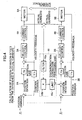
- FIG. 2 is a diagram showing an example for computing the force between the motors from the difference between the torque commands given to the two servomotors, and correcting the position deviation.
- the servo circuit unit A has a position control unit 2A, a velocity control unit 3A, and an electric current control unit 4A in the same manner as a regular servo circuit.
- the position control unit 2A receives position commands from a host control device or a host control unit, subtracts position feedback from the position command to compute the position deviation, and transmits velocity commands obtained by multiplication with the position gain to the velocity control unit 3A.
- the velocity control unit 3A receives velocity commands and transmits torque commands (electric current commands) obtained by subtracting velocity feedback from the velocity commands to the electric current control unit 4A.
- the electric current control unit 4A receives torque commands and transmits voltage commands to a power amplifier (not depicted), and the power amplifier drives the servomotor 5A on the basis of the voltage commands.
- the servomotor 5A detects velocity via an encoder (not depicted) or other means. The detected velocity is fed back to the velocity control unit 3A.
- the position feedback can be computed by integrating the velocity feedback, or obtained by detecting the position by means of an encoder disposed in the servomotor 5A.
- the servo circuit unit B has a position control unit 2B, a velocity control unit 3B, and an electric current control unit 4B in the same manner as a regular servo circuit.
- the position control unit 2B receives position commands from a host control device or a host control unit, subtracts position feedback from the position command to compute the position deviation, and transmits velocity commands obtained by multiplying the position deviation by the position gain to the velocity control unit 3B.
- the velocity control unit 3B receives velocity commands and transmits torque commands (electric current commands) obtained by subtracting velocity feedback from the velocity commands to the electric current control unit 4B.
- the electric current control unit 4B receives torque commands and transmits voltage commands to a power amplifier (not depicted), and the power amplifier drives the servomotor 5B on the basis of the voltage commands.
- the servomotor 5B detects velocity via an encoder (not depicted) or other means. The detected velocity is fed back to the velocity control unit 3B.
- the position feedback can be computed by integrating the velocity feedback, or obtained by detecting the position by means of an encoder disposed in the servomotor 5B.
- the synchronization correction processing unit 10 has a filter 10a, means 10b for calculating the position deviation offset amount, and limiting means 10c for limiting the position deviation offset amount.
- the difference between the torque command from the velocity control unit 3A and the torque command from the velocity control unit 3B is input to the synchronization correction processing unit 10.
- the synchronization correction processing unit 10 computes the force between the motors from the difference in the torque commands given to the two servomotors, and computes the position deviation offset amount from the computed force.
- the computed position deviation offset amount is added to the position deviation of the servo circuit B to correct the position deviation.
- the filter 10a extracts the low-frequency component of the difference in inputted torque commands in order to make corrections at a frequency that is lower than the frequency band of the position control unit 2A.
- the filter 10a may be composed of a low-pass filter, for example.
- the means 10b for calculating the position deviation offset amount computes the position deviation offset amount by multiplying the deviation (difference) in the torque commands by a first conversion coefficient K1.
- the first conversion coefficient K1 is a coefficient for converting the deviation (difference) in torque commands to position deviation offset amount.
- the limiting means 10c for limiting the position deviation offset amount applies a limitation so that the position deviation offset amount computed by the means 10b for calculating the position deviation offset amount does not become excessively large.
- the limiting value is set in advance.
- the position deviation offset amount obtained by way of the synchronization correction processing unit 10 is added to the position deviation of the position control unit 2B of the servo circuit unit B.
- the position deviation offset amount is not limited to being added solely to the position deviation of the position control unit 2B of the servo circuit unit B, and may be added to the position deviation of the position control unit 2A of the servo circuit unit A.
- Correcting the position deviation by way of the synchronization correction processing unit 10 reduces the physical interference between the servomotors 5A and 5B.
- FIG. 3 depicts calculation processing for the position deviation offset performed by the synchronization correction processing unit
- FIG. 2 shows an example of computing the position deviation offset from the difference in torque commands.
- FILTER ( ⁇ T) represents filter processing and allows the desired filter characteristics to be set (step S3).
- the means 10b for calculating the position deviation offset amount multiplies the deviation output Fout of the filter-processed torque commands by the first conversion coefficient K1, and calculates the position deviation offset amount Eoffset.
- the position deviation offset based on the force that acts on the two servomotors is obtained by multiplying the difference between the torque commands by the first conversion coefficient K1 (step S4).
- a limit is applied so that the computed position deviation offset amount Eoffset does not exceed a limiting value.
- the limiting value can be set in accordance with the drive system of the motor (step S5).
- Position control is carried out based on the force that acts between the servomotors by adding the position deviation offset amount to the position deviation in this manner (step S6).
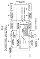
- FIG. 4 shows an example of computing the force between the motors from the difference in the actual electric currents that flow into the two servomotors, and correcting the position deviation.
- the structures of the servo circuit unit A and servo circuit unit B are the same as in FIG. 2, so a description is omitted here.
- the synchronization correction processing unit 10 has a filter 10a, means 10b for calculating the position deviation offset amount, and limiting means 10c for limiting the position deviation offset amount.
- the difference between the actual electric current from the velocity control unit 4A and the actual electric current from the velocity control unit 4B is input to the synchronization correction processing unit 10.
- the synchronization correction processing unit 10 computes the force between the motors from the difference in the actual electric currents that flow into the two servomotors, and computes the position deviation offset amount from the computed force.
- the computed position deviation offset amount is added to the position deviation of the servo circuit B to correct the position deviation.
- the filter 10a extracts the low-frequency component of the difference in inputted torque commands in order to make corrections at a frequency that is lower than the frequency band of the position control unit 2A.
- the filter 10a may be composed of a low-pass filter, for example.
- the means 10b for calculating the position deviation offset amount computes the position deviation offset amount by multiplying the deviation (difference) in the actual electric currents by a second conversion coefficient K2.
- the second conversion coefficient K2 is a coefficient for converting the deviation (difference) in actual electric currents to the position deviation offset amount.
- the limiting means 10c for limiting the position deviation offset amount applies a limitation so that the position deviation offset amount computed by the means 10b for calculating the position deviation offset amount does not become excessively large.
- the limiting value is set in advance.
- the position deviation offset amount obtained by way of the synchronization correction processing unit 10 is added to the position deviation of the position control unit 2B of the servo circuit unit B.
- the position deviation offset amount is not limited to being added solely to the position deviation of the position control unit 2B of the servo circuit unit B, and may be added to the position deviation of the position control unit 2A of the servo circuit unit A.
- Correcting the position deviation by way of the synchronization correction processing unit 10 reduces the physical interference between the servomotors 5A and 5B.
- the calculation processing for the position deviation offset performed by the synchronization correction processing unit having the structure shown in FIG. 4 may be performed in the same manner as in the flowchart in FIG. 3 by replacing the torque command with the actual electric current and replacing the conversion coefficient K with the second conversion coefficient K2.
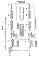
- FIG. 5 is a diagram showing an example for correcting position deviations by using a table 10d with a set relationship between the force that acts between the motors and the offset amount.
- the structures of the servo circuit unit A and servo circuit unit B are the same as the examples shown in FIGS. 2 and 4, so a description is omitted here.
- the synchronization correction processing unit 10 has recording means for computing the relationship between the torque deviation and the position deviation offset amount in advance by way of the structure in FIG. 2 or other means, and recording the relationship to the recording means.
- the relationship between the torque deviation and the position deviation offset amount is stored by means of a table or the like. When the difference (deviation) in torque commands is input, the corresponding position deviation offset amount is computed and output.
- the position deviation offset amount obtained by way of the synchronization correction processing unit 10 is added to the position deviation of the position control unit 2B of the servo circuit unit B.
- the position deviation offset amount is not limited to being added solely to the position deviation of the position control unit 2B of the servo circuit unit B, and may be added to the position deviation of the position control unit 2A of the servo circuit unit A.
- the relationship between the torque deviations and the position deviation offset amounts is stored, but a structure may be adopted whereby the relationship between the actual electric currents and the position deviation amounts is stored, the difference in actual electric currents is input, and the position deviation offset amount is output.
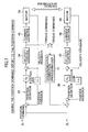
- FIG. 6 is a fourth example, and it shows a structural example for adding the position deviation offset amount to the position deviation of the position control unit of both servo circuits.
- the fifth example is an example for correcting the position command with the position processing offset amount obtained from the difference in torque commands.
- FIG. 7 is a diagram showing an example for computing the force between motors from the difference in torque commands given to the two servomotors, and correcting the position command.
- the structure of the servo circuit unit A, servo circuit unit B, and synchronization correction processing unit 10 is the same as the example shown in FIG. 2, so a description is omitted here.
- the synchronization correction processing unit 10 has a filter, means for calculating the position command offset amount, and limiting means for limiting the instruction command offset amount.
- the difference between the torque command from the velocity control unit 3A and the torque command from the velocity control unit 3B is input to the synchronization correction processing unit 10.
- the synchronization correction processing unit 10 computes the force between the motors from the difference in the torque commands given to the two servomotors, and computes the position deviation offset amount from the computed force.
- the computed position deviation offset amount is added to the position deviation of the servo circuit B to correct the position deviation.
- the filter extracts the low-frequency component of the difference in inputted torque commands in order to make corrections at a frequency that is lower than the frequency band of the position control unit 2A.
- the filter may be composed of a low-pass filter, for example.
- the means for calculating the position command offset amount computes the position command offset amount by multiplying the deviation (difference) in the torque commands by a third conversion coefficient K3.
- the third conversion coefficient K3 is a coefficient for converting the deviation (difference) in torque commands to the position command offset amount.
- the limiting means for limiting the position command offset amount applies a limitation so that the position command offset amount computed by the means for calculating the position command offset amount does not become excessively large.
- the limiting value is set in advance.
- the position command offset amount obtained by way of the synchronization correction processing unit 10 is added to the position command of the position control unit 2B of the servo circuit unit B.
- the position command offset amount is not limited to being added solely to the position command of the position control unit 2B of the servo circuit unit B, and may be added to the position command of the position control unit 2A of the servo circuit unit A.
- Correcting the position command by way of the synchronization correction processing unit 10 reduces the physical interference between the servomotors 5A and 5B.
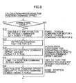
- FIG. 8 shows calculation processing for the position command offset performed by the synchronization correction processing unit
- FIG. 7 shows an example of computing the position command offset from the difference in torque commands.
- FILTER ( ⁇ T) represents filter processing and allows the desired filter characteristics to be set (step S13).
- the means for calculating the position command offset amount multiplies the deviation output Fout of the filter-processed torque commands by the third conversion coefficient K3, and calculates the position command offset amount Poffset.
- the position command offset based on the force that acts on the two servomotors is obtained by multiplying the difference between the torque commands by the third conversion coefficient K3 (step S14).
- a limit is applied so that the computed position command offset amount Poffset does not exceed a limiting value.
- the limiting value can be set in accordance with the drive system of the motor (step S15).
- Position control is carried out based on the force that acts between the servomotors by adding the position command offset amount Poffset to the position command MCMD in this manner (step S16).
- a position command is corrected based on a position command offset amount obtained from the difference in the actual electric currents.
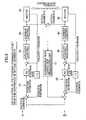
- FIG. 9 shows a structural example of an aspect in which a position command is corrected and in which the force that acts between the servomotors is computed from the difference in the actual electric currents that flow into the motors.
- the structures of the servo circuit unit A, servo circuit unit B, and the synchronization correction processing unit 10 are the same as in FIGS. 2 and 4, so a description is omitted here.
- the synchronization correction processing unit 10 has a filter, means for calculating position command offset amount, and limiting means for limiting the position command offset amount.
- the difference between the actual electric current from the velocity control unit 4A and the actual electric current from the velocity control unit 4B is input to the synchronization correction processing unit 10.
- the synchronization correction processing unit 10 computes the force between the motors from the difference in the actual electric currents that flow into the two servomotors, and computes the position command offset amount from the computed force.
- the computed position command offset amount is added to the position command of the servo circuit B to correct the position deviation.
- the filter extracts the low-frequency component from the difference in the actual inputted electric currents in order to make corrections at a frequency that is lower than the frequency band of the position control unit 2A.
- the filter may be composed of a low-pass filter, for example.
- the means for calculating the position command offset amount computes the position command offset amount by multiplying the deviation (difference) in the actual electric currents by a fourth conversion coefficient K4.
- the fourth conversion coefficient K4 is a coefficient for converting the deviation (difference) in actual electric currents to the position command offset amount.
- the limiting means for limiting the position command offset amount applies a limitation so that the position command offset amount computed by the means for calculating the position command offset amount does not become excessively large.
- the limiting value is set in advance.
- the position command offset amount obtained by way of the synchronization correction processing unit 10 is added to the position command of the position control unit 2B of the servo circuit unit B.
- the position command offset amount is not limited to being added solely to the position command of the position control unit 2B of the servo circuit unit B, and may be added to the position command of the position control unit 2A of the servo circuit unit A.
- Correcting the position command by way of the synchronization correction processing unit 10 reduces the physical interference between the servomotor 5A and servomotor 5B.
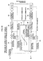
- the position command is corrected by using a table with a set relationship between the torque deviations and position command offsets.
- FIG. 10 is a diagram showing an example for correcting position commands by using the table with the set relationship between the force that acts between the motors and the offset amount.
- the structures of the servo circuit unit A and servo circuit unit B are the same as the examples shown in FIG. 5, so a description is omitted here.
- the synchronization correction processing unit 10 has recording means for computing the relationship between the torque deviation and the position command offset amount in advance by way of the structure in FIG. 9 or other means, and recording the relationship to the recording means.
- the difference (deviation) in torque commands is input, the corresponding position command offset amount is computed and output with reference to the table.
- the position command offset amount obtained by way of the synchronization correction processing unit 10 is added to the position command of the position control unit 2B of the servo circuit unit B.
- the position command offset amount is not limited to being added solely to the position command of the position control unit 2B of the servo circuit unit B, and may be added to the position command of the position control unit 2A of the servo circuit unit A.
- the relationship between the torque deviations and the position command offset amounts is stored, but a structure may be adopted whereby the relationship between the actual electric current deviations and the position command offset amounts is stored, the difference in actual electric currents is input, and the position command offset amount is output.
- the position command offset amount that is output from the synchronization processing unit 10 is added to the position command of the position control unit of one of the servo circuits, but this amount may also be added to the position command of the position control units of both servo circuits.
- FIG. 11 is an eighth example, and it shows a structural example for adding the position command offset amount to the position command of the position control unit of both servo circuits.
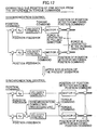
- FIG. 12 is a diagram comparing conventional synchronous control and synchronous control according to the present invention.
- Conventional synchronous control is carried out by bringing position commands and position feedback detected by a position detector into agreement. Because control is carried out for each motor, force in the pulling direction is generated in one motor 1 and force in the pushing direction is generated in the other motor 2 due to the position displacement caused by thermal expansion or position detector errors in the position of both motors. Stress is applied to the both motors due to the force that is generated in opposing directions.
- the synchronous control of the present invention is performed such that instead of controlling the position so that the position feedback values from the motors are brought into agreement with the position command, the force that acts between the motors is computed, and control is carried out so as to reduce the force that acts between the motors.
- stress that is applied to both motors can be reduced because control is carried out so as to reduce the force that acts on both motors, even when displacement occurs due to thermal expansion and position detector errors in the position of both motors.
- FIGS. 13A and 13B show the relationship between the electric current command and the position deviation during motor feed.
- FIG. 13A shows a situation in which the synchronous control of the present invention is not applied
- FIG. 13B shows a situation in which the synchronous control of the present invention is applied.
- FIG. 13A the electric current commands to both motors become considerable due to the fact that the two motors are pulling against each other.
- FIG. 13B on the other hand, the phenomenon whereby the two motors pull against each other is resolved, and the electric current commands to both motors becomes smaller. The position deviation is also made smaller.
- FIGS. 13A and 13B show a situation in which the motor is moving and a situation in which the motor is stopped.
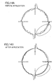
- FIGS. 14A and 14B shows position deviations during circular correction.
- FIG. 14A shows a situation in which the synchronous control of the present invention is not applied
- FIG. 14B shows a situation in which the synchronous control of the present invention is applied.
- Described below is an example for calculating the position deviation offset amount from the difference in torque commands and correcting the position deviation, but the same applies to an example in which the position deviation offset amount is calculated from the difference in actual electric currents, an example in which a table of torque values/position deviation offset amounts is used, an example in which corrections are applied to the two motors, and the like, so a description has been omitted.
- FIG. 15 is an example for calculating the position deviation offset amount from the difference in torque commands, and the structure may be substantially the same as in FIG. 2.
- the synchronization correction processing unit 10 shown in FIG. 15 is equivalent to one in which a position deviation offset calculation processor 10e is added to the synchronization correction processing unit 10 shown in FIG. 2.
- the position deviation offset calculation processor 10e calculates the position deviation offset amount when the difference between the forces on the two servomotors exceeds a predetermined value. When the difference between the forces on the two servomotors is small and the predetermined value has not been exceeded, the position deviation offset amount is not calculated.
- the position deviation offset calculation processor 10e outputs "0" when the difference between the forces on the two servomotors is equal to or less than the predetermined value (base), and when the difference exceeds the predetermined value, the difference or the value resulting from subtracting the predetermined value from the difference is output.
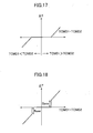
- FIGS. 17 and 18 are output examples of the position deviation offset calculation processor 10e, wherein the difference (TCMD1 - TCMD2) between the forces on the two servomotors is plotted on the axis of abscissa, and the output ⁇ T is plotted on the axis of ordinate.
- the output example shown in FIG. 17 shows that "0" is output when the difference (TCMD1 - TCMD2) is equal to or less than the predetermined value (base), and when the difference (TCMD1 - TCMD2) exceeds a predetermined value, the value (TCMD1 - TCMD2 - base) resulting from subtracting the predetermined value from the difference is output.
- the output example shown in FIG. 18 shows that "0" is output when the difference is equal to or less than the predetermined value, and outputs the difference (TCMD1 - TCMD2) when the difference exceeds the predetermined value.
- the synchronization correction processing unit 10 concludes that there is no difference between the forces on the servomotors when the difference (TCMD1 - TCMD2) between the forces on the two servomotors is equal to or less than the predetermined value, and the position deviation offset calculation processor 10e does not output the position deviation offset amount.
- the position deviation offset calculation processor 10e outputs the difference between the forces on the two servomotors, and the synchronization correction processing unit 10 calculates the position deviation offset amount on the basis of this difference.
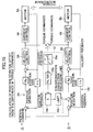
- the flowchart shown in FIG. 16 depicts calculation processing for the position deviation carried out by the synchronization correction processing unit, and shows an example of computing a position deviation offset from the difference in torque commands shown in FIG. 15.
- the position deviation offset calculation processor 10e has the output characteristics shown in FIG. 17.
- step S22 The flowchart shown in FIG. 16 is substantially the same as the flowchart shown in FIG. 3, and differs on the point of the calculation output provided in the difference calculation step (step S22), with the other steps being the same. In view of the above, only step S22 is described here.
- step S22 the deviation ⁇ T, which is the output of the position deviation offset calculation processor 10e, is allowed to output the greater of (TCMD1 - TCMD2 - base) and 0 when the torque command TCMD1 of the motor 1 is greater than the torque command TCMD2 of the motor 2, and to output the larger of (TCMD1 - TCMD2 + base) and 0 when the torque command TCMD1 of the motor 1 is less than the torque command TCMD2 of the motor 2, as shown in FIG. 17.
- step S22 After the deviation ⁇ T is calculated in step S22, the velocity command is calculated in steps S23 to S27 with the same processing as in steps S3 to S7 in the flowchart in FIG. 3.
- FIG. 19 is an example for calculating the position command offset amount from the difference in the torque commands, and it may have substantially the same structure as the structure shown in FIG. 7.
- the synchronization correction processing unit 10 shown in FIG. 19 is equivalent to one in which the position deviation offset calculation processor 10e is added to the synchronization correction processing unit 10 shown in FIG. 7.
- the position deviation offset calculation processor 10e calculates the position deviation offset amount when the difference between the forces on the two servomotors exceeds a predetermined value. When the difference between the forces on the two servomotors is small and the predetermined value has not been exceeded, the position deviation offset amount is not calculated.
- the position deviation offset calculation processor 10e outputs "0" when the difference between the forces on the two servomotors is equal to or less than the predetermined value (base), and when the difference exceeds the predetermined value, this difference or the value resulting from subtracting the predetermined value from the difference is output.
- the output characteristics of the position deviation offset calculation processor 10e can be the same as in the examples shown in FIGS. 17 and 18.
- the synchronization correction processing unit 10 concludes that there is no difference between the forces on the servomotors when the difference (TCMD1 - TCMD2) between the forces on the two servomotors is equal to or less than a predetermined value (base), and the position deviation offset calculation processor 10e does not output the position deviation offset amount.
- the position deviation offset calculation processor 10e outputs the difference between the forces on the two servomotors, and the synchronization correction processing unit 10 calculates the position deviation offset amount.
- the flowchart shown in FIG. 20 depicts calculation processing for the position command carried out by the synchronization correction processing unit, and shows an example of computing the position command offset from the difference in torque commands shown in FIG. 15.
- the position deviation offset calculation processor 10e has the output characteristics shown in FIG. 17 or 18.
- step S32 The flowchart shown in FIG. 20 is substantially the same as the flowchart shown in FIG. 3 and differs on the point of the calculation output provided in the difference calculation step (step S32), with the other steps being the same. In view of the above, only step S32 is described here.
- step S32 for calculating the difference in torque commands the deviation ⁇ T, which is the output of the position deviation offset calculation processor 10e, is allowed to output the greater of (TCMD1 - TCMD2 - base) and 0 when the torque command TCMD1 of the motor 1 is greater than the torque command TCMD2 of the motor 2, and to output the greater of (TCMD1 - TCMD2 + base) and 0 when the torque command TCMD1 of the motor 1 is less than the torque command TCMD2 of the motor 2, as shown in FIG. 17, or FIG. 18.
- step S32 After the deviation ⁇ T is calculated in step S32, the position command offset amount is calculated and added to the position command in the steps S33 to S36 with the same processing as in steps S13 to S16 of the flowchart in FIG. 8.
- a base is provided to the forces that act between the motors, and position deviations generated in the slave can be prevented by making corrections only when the difference in the forces is larger than the base.
Landscapes
- Engineering & Computer Science (AREA)
- Power Engineering (AREA)
- Control Of Multiple Motors (AREA)
- Control Of Position Or Direction (AREA)
- Numerical Control (AREA)
Abstract
Description
Claims (15)
- A synchronous control device for controllably driving a servomotor, comprising:a position control unit for outputting velocity commands at each predetermined cycle on the basis of the position deviation between position feedback from a position detector and position command transmitted at each predetermined sampling cycle from a host control device or a host control unit, anda velocity control unit for outputting torque commands at each predetermined cycle on the basis of velocity feedback from velocity detectors and the velocity commands, whereinsaid synchronous control device synchronously controls two servomotors for driving the same control object and further comprises means for reducing the force that acts between the two servomotors on the basis of the force that acts between the two servomotors.
- The synchronous control device according to claim 1, wherein the position control unit comprises:a position deviation offset calculation processor for calculating the offset amount of the position deviation on the basis of the force that acts between the two servomotors, andmeans for adding the position deviation offset amount calculated by the position deviation offset calculation processor to the position deviation.
- The synchronous control device according to claim 2, wherein the position deviation offset calculation processor computes the force that acts between the two servomotors from the difference in the torque commands given to the two servomotors, and calculates the position deviation offset amount by multiplying the computed difference by a conversion coefficient.
- The synchronous control device according to claim 2, wherein the position deviation offset calculation processor computes the force that acts between the two servomotors from the actual electric currents that flow into the two servomotors, and calculates the position deviation offset amount by multiplying the computed difference by a conversion coefficient.
- The synchronous control device according to claim 1, wherein the position control unit comprises a position deviation offset calculation processor for calculating the offset amount of the position deviation when the difference between the forces on the two servomotors exceeds a fixed value, and means for adding the position deviation offset amount calculated by the position deviation offset calculation processor to the position deviation.
- The synchronous control device according to claim 5, wherein the position deviation offset calculation processor computes the force that acts between the two servomotors from the difference in the torque commands given to the two servomotors, and calculates the position deviation offset amount by multiplying the computed difference, or the quantity obtained by subtracting a fixed value from the difference, by a conversion coefficient.
- The synchronous control device according to claim 5, wherein the position deviation offset calculation processor computes the force that acts between the two servomotors from the difference in the actual electric currents that flow into the two servomotors, and calculates the position deviation offset amount by multiplying the computed difference, or the quantity obtained by subtracting a fixed value from the difference, by a conversion coefficient.
- The synchronous control device according to any of claims 2 to 7, wherein the position deviation offset calculation processor comprises adjusting means for changing the position deviation offset amount at a frequency that is sufficiently lower than the frequency band of the position control unit.
- The synchronous control device according to claim 1, wherein the position control unit comprises a position command offset calculation processor for calculating the offset amount of said position command on the basis of the force that acts between the two servomotors, and means for adding the position command offset amount that was calculated by the position command offset calculation processor to the position command.
- The synchronous control device according to claim 9, wherein the position deviation offset calculation processor computes the force that acts between the two servomotors from the difference in the torque commands given to the two servomotors, and calculates the position command offset amount by multiplying the computed difference by a conversion coefficient.
- The synchronous control device according to claim 9, wherein the position deviation offset calculation processor computes the force that acts between the two servomotors from the actual electric currents that flow into the two servomotors, and calculates the position command offset amount by multiplying the computed difference by a conversion coefficient.
- The synchronous control device according to claim 1, wherein the position control unit comprises a position command offset calculation processor for calculating the offset amount of the position command when the difference between the forces on the two servomotors exceeds a fixed value, and means for adding the position command offset amount calculated by the position command offset calculation processor to the position command.
- The synchronous control device according to claim 12, wherein the position command offset calculation processor computes the force that acts between the two servomotors from the difference in the torque commands given to the two servomotors, and calculates the position command offset amount by multiplying the computed difference, or the quantity obtained by subtracting a fixed value from the difference, by a conversion coefficient.
- The synchronous control device according to claim 12, wherein the position command offset calculation processor computes the force that acts between the two servomotors from the difference in the actual electric currents that flow into the two servomotors, and calculates the position command offset amount by multiplying the computed difference, or the quantity obtained by subtracting a fixed value from the difference, by a conversion coefficient.
- The synchronous control device according to any of claims 9 to 14, wherein the position command offset calculation processor comprises adjusting means for changing the position command offset amount at a frequency that is sufficiently lower than the frequency band of the position control unit.
Applications Claiming Priority (4)
| Application Number | Priority Date | Filing Date | Title |
|---|---|---|---|
| JP2003056922 | 2003-03-04 | ||
| JP2003056922 | 2003-03-04 | ||
| JP2004005924 | 2004-01-13 | ||
| JP2004005924A JP3923047B2 (en) | 2003-03-04 | 2004-01-13 | Synchronous control device |
Publications (3)
| Publication Number | Publication Date |
|---|---|
| EP1455438A2 true EP1455438A2 (en) | 2004-09-08 |
| EP1455438A3 EP1455438A3 (en) | 2006-06-21 |
| EP1455438B1 EP1455438B1 (en) | 2009-12-23 |
Family
ID=32828974
Family Applications (1)
| Application Number | Title | Priority Date | Filing Date |
|---|---|---|---|
| EP04251235A Expired - Lifetime EP1455438B1 (en) | 2003-03-04 | 2004-03-03 | Synchronous control device |
Country Status (5)
| Country | Link |
|---|---|
| US (1) | US7183739B2 (en) |
| EP (1) | EP1455438B1 (en) |
| JP (1) | JP3923047B2 (en) |
| CN (1) | CN100349080C (en) |
| DE (1) | DE602004024736D1 (en) |
Cited By (8)
| Publication number | Priority date | Publication date | Assignee | Title |
|---|---|---|---|---|
| RU2326488C1 (en) * | 2006-10-24 | 2008-06-10 | Общество с ограниченной ответственностью "Инт-КЛАСС" | Multimotor frequency regulated electric drive |
| WO2009010147A1 (en) * | 2007-07-17 | 2009-01-22 | Sew-Eurodrive Gmbh & Co. Kg | System, and method |
| EP1821168A3 (en) * | 2006-02-16 | 2009-05-06 | Fanuc Ltd | Controller for servomotor |
| RU2419953C1 (en) * | 2007-06-07 | 2011-05-27 | Мицубиси Электрик Корпорейшн | Motor control device |
| US8228008B2 (en) | 2007-06-07 | 2012-07-24 | Mitsubishi Electric Corporation | Motor controlling apparatus |
| JP2013027254A (en) * | 2011-07-25 | 2013-02-04 | Ito Denki Kk | Motor control system, control device, and combination of motorized roller and control device |
| RU2656999C1 (en) * | 2017-07-11 | 2018-06-08 | федеральное государственное бюджетное образовательное учреждение высшего образования "Национальный исследовательский университет "МЭИ" (ФГБОУ ВО "НИУ "МЭИ") | Swivel platform multi-motor drive |
| DE102017205791B4 (en) * | 2016-04-12 | 2020-03-19 | Fanuc Corporation | Servo control device for driving a variety of motors |
Families Citing this family (54)
| Publication number | Priority date | Publication date | Assignee | Title |
|---|---|---|---|---|
| JP4283214B2 (en) * | 2004-12-16 | 2009-06-24 | ファナック株式会社 | Machine tip control device |
| JP2006201148A (en) * | 2004-12-22 | 2006-08-03 | Toshiba Mach Co Ltd | Signal processing device, signal processing method, signal processing program, recording medium with the signal processing program stored, speed detection device, and servo mechanism |
| CN100524136C (en) * | 2005-03-07 | 2009-08-05 | 三菱电机株式会社 | Drive control system and mechanical control device |
| DE112006002501T5 (en) * | 2005-09-26 | 2008-08-07 | Kabushiki Kaisha Yaskawa Denki, Kitakyushu | Initial pole position detection apparatus and method for a synchronous AC motor |
| JP4080504B2 (en) | 2005-10-18 | 2008-04-23 | ファナック株式会社 | Die cushion control device |
| JP4760912B2 (en) | 2006-09-28 | 2011-08-31 | 三菱電機株式会社 | Servo control device |
| JP2008126327A (en) * | 2006-11-17 | 2008-06-05 | Fanuc Ltd | Moving locus display device |
| JP2008302449A (en) * | 2007-06-06 | 2008-12-18 | Fanuc Ltd | Robot control device |
| JP4323542B2 (en) * | 2007-10-22 | 2009-09-02 | ファナック株式会社 | Motor control device with learning control function |
| FR2930936B1 (en) | 2008-05-07 | 2010-08-13 | Etel Sa | SYSTEM FOR CONTROLLING A DOUBLE-MEDIUM DRIVING GANTRY |
| JP4620159B2 (en) * | 2009-05-21 | 2011-01-26 | ファナック株式会社 | Servo motor control device that controls periodic reciprocating motion |
| JP4853842B2 (en) | 2010-01-12 | 2012-01-11 | 株式会社安川電機 | Synchronous control device |
| JP4880763B2 (en) * | 2010-01-19 | 2012-02-22 | 山洋電気株式会社 | Motor control method and apparatus |
| DE112011100347B4 (en) | 2010-01-27 | 2020-07-23 | Mitsubishi Electric Corporation | Engine control device |
| CN102079484B (en) * | 2010-02-26 | 2013-05-22 | 上海海事大学 | Synchronous Control System of Double Spreaders for Double Hoisting Bridge |
| JP5375703B2 (en) * | 2010-03-26 | 2013-12-25 | ブラザー工業株式会社 | Numerical controller |
| CN101841286B (en) * | 2010-05-28 | 2011-11-16 | 济南二机床集团有限公司 | Double motor driven backlash eliminating device and backlash eliminating method |
| JP5073126B1 (en) * | 2011-03-31 | 2012-11-14 | コマツNtc株式会社 | Crankshaft mirror and method of manufacturing crankshaft |
| US20120319637A1 (en) * | 2011-06-20 | 2012-12-20 | Nikon Corporation | Synchronization control devices and methods |
| JP5314110B2 (en) * | 2011-11-25 | 2013-10-16 | ファナック株式会社 | Motor controller for synchronous control of master axis and slave axis |
| JP5655806B2 (en) * | 2012-03-23 | 2015-01-21 | 横河電機株式会社 | Synchronizer and field device |
| CN102710183B (en) * | 2012-06-13 | 2016-01-20 | 苏州汇川技术有限公司 | Many motors cross-couplings synchronous control system and method |
| JP5739400B2 (en) * | 2012-11-30 | 2015-06-24 | ファナック株式会社 | Servo control device having position correction function of driven body |
| JPWO2014102895A1 (en) * | 2012-12-25 | 2017-01-12 | 三菱電機株式会社 | Positioning device and positioning method |
| JP5642828B2 (en) * | 2013-03-28 | 2014-12-17 | ファナック株式会社 | Synchronous control device for synchronizing two axes with each other |
| JP5642848B1 (en) * | 2013-07-19 | 2014-12-17 | ファナック株式会社 | Motor control device for controlling two motors to drive one driven body |
| US10589973B2 (en) | 2013-10-25 | 2020-03-17 | Ats Automation Tooling Systems Inc. | Flexible feeding and closing machine for hinged caps |
| JP5710730B1 (en) * | 2013-10-28 | 2015-04-30 | ファナック株式会社 | Machine tool control device with rotary indexing device |
| CN103676653B (en) * | 2013-12-16 | 2017-01-18 | 成都乐创自动化技术股份有限公司 | Servo synchronous control method and system applied to gantry mechanism |
| JP5778750B2 (en) * | 2013-12-24 | 2015-09-16 | ファナック株式会社 | Control device for injection molding machine having function of reducing synchronization error |
| JP5815780B2 (en) | 2014-03-19 | 2015-11-17 | ファナック株式会社 | Motor controller that can protect the machined surface when an abnormal load occurs |
| JP5815784B2 (en) * | 2014-04-08 | 2015-11-17 | ファナック株式会社 | Servo controller for reducing synchronization error in synchronous machining |
| JP5897662B2 (en) * | 2014-07-30 | 2016-03-30 | ファナック株式会社 | Servo motor control device that improves multi-axis machining accuracy |
| JP6312548B2 (en) * | 2014-07-31 | 2018-04-18 | ファナック株式会社 | Servo motor control device having self-measuring function and self-monitoring function of machine stiffness |
| JP5927259B2 (en) * | 2014-09-30 | 2016-06-01 | ファナック株式会社 | Robot system for force control |
| DE102015117813B4 (en) * | 2014-10-21 | 2025-02-06 | Denso Corporation | Control unit and control method for rotating electrical machine |
| JP6154435B2 (en) * | 2015-07-09 | 2017-06-28 | ファナック株式会社 | Servo control device with function to display online automatic adjustment status of control system |
| JP6106226B2 (en) | 2015-07-31 | 2017-03-29 | ファナック株式会社 | Machine learning device for learning gain optimization, motor control device including machine learning device, and machine learning method |
| TWI558089B (en) | 2015-08-06 | 2016-11-11 | 財團法人工業技術研究院 | Synchronous control system for multi-axis motors and method thereof |
| JP6721307B2 (en) * | 2015-09-16 | 2020-07-15 | ファナック株式会社 | Machine tool controller with multiple axes |
| CN105186951B (en) * | 2015-09-18 | 2018-06-19 | 李鹏 | A kind of four closed loop stepping servo control methods |
| CN105676897B (en) * | 2016-04-14 | 2018-11-13 | 重庆交通大学 | Multi-machine system intelligent coordination control method |
| US10250170B2 (en) | 2016-08-24 | 2019-04-02 | Mitsubishi Electric Corporation | Motor control device |
| CN106401239B (en) * | 2016-08-31 | 2019-04-30 | 北京首钢自动化信息技术有限公司 | The traveling control method and device of comb teeth carrier in stereo garage |
| CN109842281B (en) * | 2017-11-24 | 2020-12-01 | 南京德朔实业有限公司 | electrical tools |
| JP6683748B2 (en) * | 2018-02-23 | 2020-04-22 | ファナック株式会社 | Numerical control device |
| CN110856928A (en) | 2018-08-22 | 2020-03-03 | 新世代机器人暨人工智慧股份有限公司 | Automatic control method and automatic control device |
| JP7031637B2 (en) * | 2019-04-04 | 2022-03-08 | オムロン株式会社 | Control device, adjustment required part identification method, torque balance adjustment method and program |
| JP7107269B2 (en) * | 2019-04-04 | 2022-07-27 | オムロン株式会社 | CONTROL DEVICE, TORQUE BALANCE ADJUSTMENT METHOD AND PROGRAM |
| TWI726498B (en) | 2019-11-22 | 2021-05-01 | 財團法人工業技術研究院 | Method for synchronous control of gantry mechanism with online inertia matching |
| CN117377914B (en) * | 2021-06-02 | 2026-05-01 | 发那科株式会社 | Motion control device and program |
| CN114368709B (en) * | 2022-01-29 | 2023-08-04 | 西门子(中国)有限公司 | Horizontal double-drive control method and device for stacker |
| CN115306637B (en) * | 2022-08-12 | 2025-05-02 | 深圳市汇川技术股份有限公司 | Variable pitch drive system, variable pitch drive and master-slave motor driving method |
| CN117140522A (en) * | 2023-09-20 | 2023-12-01 | 西门子(中国)有限公司 | Multi-axis collaborative control method, device, electronic equipment and storage medium |
Family Cites Families (26)
| Publication number | Priority date | Publication date | Assignee | Title |
|---|---|---|---|---|
| JPH01217604A (en) * | 1988-02-26 | 1989-08-31 | Fanuc Ltd | Synchronizing control system |
| JPH01228752A (en) | 1988-03-10 | 1989-09-12 | Fanuc Ltd | Spindle synchronizing system |
| EP0423357B1 (en) * | 1989-04-10 | 1996-07-03 | Kabushiki Kaisha Yaskawa Denki Seisakusho | Device for controlling servo motor |
| JP2581797B2 (en) * | 1989-04-27 | 1997-02-12 | オ−クマ株式会社 | Synchronous control method and device |
| JP2709969B2 (en) * | 1989-12-12 | 1998-02-04 | ファナック株式会社 | Servo motor control method |
| JPH03204009A (en) * | 1989-12-29 | 1991-09-05 | Matsushita Electric Ind Co Ltd | 2-axis synchronous drive device |
| US5252902A (en) * | 1990-03-02 | 1993-10-12 | Kabushiki Kaisha Sg | Servo control system |
| JP2518457B2 (en) * | 1990-07-05 | 1996-07-24 | 三菱電機株式会社 | How to synchronize the feed axis of the lathe |
| US5502602A (en) * | 1992-07-21 | 1996-03-26 | Sony Corporation | Recording and/reproducing apparatus having no capstan and no pinch roller and method of controlling the same |
| JPH06351270A (en) * | 1993-06-04 | 1994-12-22 | Canon Inc | Controller for ultrasonic motor |
| JP3518029B2 (en) * | 1994-05-09 | 2004-04-12 | 三菱電機株式会社 | Servo system controller |
| JP3824668B2 (en) * | 1994-10-19 | 2006-09-20 | 株式会社明電舎 | Control device for electric servo motor governor |
| JPH08328663A (en) | 1995-06-01 | 1996-12-13 | Hitachi Zosen Corp | Robot device drive controller |
| JP3369802B2 (en) * | 1995-07-24 | 2003-01-20 | オークマ株式会社 | Moving body drive device |
| US5886494A (en) * | 1997-02-06 | 1999-03-23 | Camelot Systems, Inc. | Positioning system |
| JP3478946B2 (en) * | 1997-07-02 | 2003-12-15 | 東芝機械株式会社 | Servo adjustment method and device |
| GB2342468B (en) * | 1997-07-02 | 2001-09-12 | Mitsubishi Electric Corp | Synchronization control device for servomotors |
| JP3755054B2 (en) * | 1998-02-27 | 2006-03-15 | 三菱電機株式会社 | Synchronous control device |
| JPH11305839A (en) | 1998-04-21 | 1999-11-05 | Fanuc Ltd | Method for controlling plural servo motors |
| JP2000301385A (en) * | 1999-04-20 | 2000-10-31 | Mitsubishi Electric Corp | Press apparatus and method of manufacturing pressed product |
| CN1149457C (en) * | 1999-06-04 | 2004-05-12 | 株式会社安川电机 | Motor Position Controller |
| JP2001198765A (en) * | 2000-01-18 | 2001-07-24 | Toshiba Mach Co Ltd | Method and device for controlling position of feeding device |
| JP4096481B2 (en) * | 2000-01-21 | 2008-06-04 | 株式会社Ihi | Servo control device |
| US6315903B1 (en) * | 2000-03-24 | 2001-11-13 | Downstream Environmental, Llc | Method for processing liquid waste |
| JP3492583B2 (en) * | 2000-03-27 | 2004-02-03 | ファナック株式会社 | Servo control device |
| JP2003200332A (en) * | 2001-12-27 | 2003-07-15 | Fanuc Ltd | Control device for gear machining |
-
2004
- 2004-01-13 JP JP2004005924A patent/JP3923047B2/en not_active Expired - Fee Related
- 2004-03-03 EP EP04251235A patent/EP1455438B1/en not_active Expired - Lifetime
- 2004-03-03 US US10/790,697 patent/US7183739B2/en not_active Expired - Lifetime
- 2004-03-03 DE DE602004024736T patent/DE602004024736D1/en not_active Expired - Lifetime
- 2004-03-04 CN CNB2004100065341A patent/CN100349080C/en not_active Expired - Fee Related
Cited By (8)
| Publication number | Priority date | Publication date | Assignee | Title |
|---|---|---|---|---|
| EP1821168A3 (en) * | 2006-02-16 | 2009-05-06 | Fanuc Ltd | Controller for servomotor |
| RU2326488C1 (en) * | 2006-10-24 | 2008-06-10 | Общество с ограниченной ответственностью "Инт-КЛАСС" | Multimotor frequency regulated electric drive |
| RU2419953C1 (en) * | 2007-06-07 | 2011-05-27 | Мицубиси Электрик Корпорейшн | Motor control device |
| US8228008B2 (en) | 2007-06-07 | 2012-07-24 | Mitsubishi Electric Corporation | Motor controlling apparatus |
| WO2009010147A1 (en) * | 2007-07-17 | 2009-01-22 | Sew-Eurodrive Gmbh & Co. Kg | System, and method |
| JP2013027254A (en) * | 2011-07-25 | 2013-02-04 | Ito Denki Kk | Motor control system, control device, and combination of motorized roller and control device |
| DE102017205791B4 (en) * | 2016-04-12 | 2020-03-19 | Fanuc Corporation | Servo control device for driving a variety of motors |
| RU2656999C1 (en) * | 2017-07-11 | 2018-06-08 | федеральное государственное бюджетное образовательное учреждение высшего образования "Национальный исследовательский университет "МЭИ" (ФГБОУ ВО "НИУ "МЭИ") | Swivel platform multi-motor drive |
Also Published As
| Publication number | Publication date |
|---|---|
| US20040180606A1 (en) | 2004-09-16 |
| JP2004288164A (en) | 2004-10-14 |
| JP3923047B2 (en) | 2007-05-30 |
| CN100349080C (en) | 2007-11-14 |
| EP1455438A3 (en) | 2006-06-21 |
| US7183739B2 (en) | 2007-02-27 |
| DE602004024736D1 (en) | 2010-02-04 |
| EP1455438B1 (en) | 2009-12-23 |
| CN1527170A (en) | 2004-09-08 |
Similar Documents
| Publication | Publication Date | Title |
|---|---|---|
| EP1455438B1 (en) | Synchronous control device | |
| JP4575508B1 (en) | Servo control device for dual position feedback control | |
| JP4760912B2 (en) | Servo control device | |
| JP4361071B2 (en) | Servo control device | |
| US8436565B2 (en) | Motor controller for tandem control | |
| US8896255B2 (en) | Servo controller having function for correcting amount of expansion/contraction of ball screw | |
| EP0952504A2 (en) | Method of and apparatus for controlling a plurality of servomotors | |
| JP2008225533A (en) | Servo controller | |
| EP1821168B1 (en) | Controller for servomotor | |
| JP5943650B2 (en) | Servo control device and servo control method | |
| JP4867105B2 (en) | Numerical controller | |
| EP1684138B1 (en) | Position control device, measuring device and machining device | |
| JP4226420B2 (en) | Position control device | |
| JP3370040B2 (en) | Speed control device | |
| JP5388605B2 (en) | Motor synchronous control device | |
| CN105897069B (en) | Motor control device | |
| KR100457411B1 (en) | Position control system | |
| WO2021124603A1 (en) | Motor control device and motor control method | |
| JP4712063B2 (en) | Position control device | |
| KR20010081999A (en) | Position control method of convey driving unit and position control system | |
| JP3308656B2 (en) | Servo motor control method | |
| JP2005099981A (en) | Synchronous operation method | |
| EP3598248B1 (en) | Control system | |
| JP4507071B2 (en) | Motor control device | |
| CN113632036A (en) | Control device |
Legal Events
| Date | Code | Title | Description |
|---|---|---|---|
| PUAI | Public reference made under article 153(3) epc to a published international application that has entered the european phase |
Free format text: ORIGINAL CODE: 0009012 |
|
| AK | Designated contracting states |
Kind code of ref document: A2 Designated state(s): AT BE BG CH CY CZ DE DK EE ES FI FR GB GR HU IE IT LI LU MC NL PL PT RO SE SI SK TR |
|
| AX | Request for extension of the european patent |
Extension state: AL HR LT LV MK |
|
| PUAL | Search report despatched |
Free format text: ORIGINAL CODE: 0009013 |
|
| AK | Designated contracting states |
Kind code of ref document: A3 Designated state(s): AT BE BG CH CY CZ DE DK EE ES FI FR GB GR HU IE IT LI LU MC NL PL PT RO SE SI SK TR |
|
| AX | Request for extension of the european patent |
Extension state: AL LT LV MK |
|
| 17P | Request for examination filed |
Effective date: 20061004 |
|
| AKX | Designation fees paid |
Designated state(s): DE |
|
| 17Q | First examination report despatched |
Effective date: 20081216 |
|
| GRAP | Despatch of communication of intention to grant a patent |
Free format text: ORIGINAL CODE: EPIDOSNIGR1 |
|
| GRAS | Grant fee paid |
Free format text: ORIGINAL CODE: EPIDOSNIGR3 |
|
| GRAA | (expected) grant |
Free format text: ORIGINAL CODE: 0009210 |
|
| AK | Designated contracting states |
Kind code of ref document: B1 Designated state(s): DE |
|
| REF | Corresponds to: |
Ref document number: 602004024736 Country of ref document: DE Date of ref document: 20100204 Kind code of ref document: P |
|
| PLBE | No opposition filed within time limit |
Free format text: ORIGINAL CODE: 0009261 |
|
| STAA | Information on the status of an ep patent application or granted ep patent |
Free format text: STATUS: NO OPPOSITION FILED WITHIN TIME LIMIT |
|
| 26N | No opposition filed |
Effective date: 20100924 |
|
| REG | Reference to a national code |
Ref country code: DE Ref legal event code: R082 Ref document number: 602004024736 Country of ref document: DE Representative=s name: HASELTINE LAKE LLP, DE |
|
| REG | Reference to a national code |
Ref country code: DE Ref legal event code: R082 Ref document number: 602004024736 Country of ref document: DE Representative=s name: HL KEMPNER PATENTANWALT, RECHTSANWALT, SOLICIT, DE |
|
| PGFP | Annual fee paid to national office [announced via postgrant information from national office to epo] |
Ref country code: DE Payment date: 20210216 Year of fee payment: 18 |
|
| REG | Reference to a national code |
Ref country code: DE Ref legal event code: R119 Ref document number: 602004024736 Country of ref document: DE |
|
| PG25 | Lapsed in a contracting state [announced via postgrant information from national office to epo] |
Ref country code: DE Free format text: LAPSE BECAUSE OF NON-PAYMENT OF DUE FEES Effective date: 20221001 |