EP1455403A2 - Electronic apparatus, and state display control method - Google Patents
Electronic apparatus, and state display control method Download PDFInfo
- Publication number
- EP1455403A2 EP1455403A2 EP04004862A EP04004862A EP1455403A2 EP 1455403 A2 EP1455403 A2 EP 1455403A2 EP 04004862 A EP04004862 A EP 04004862A EP 04004862 A EP04004862 A EP 04004862A EP 1455403 A2 EP1455403 A2 EP 1455403A2
- Authority
- EP
- European Patent Office
- Prior art keywords
- fuel cell
- unit
- tank
- electronic apparatus
- fuel
- Prior art date
- Legal status (The legal status is an assumption and is not a legal conclusion. Google has not performed a legal analysis and makes no representation as to the accuracy of the status listed.)
- Withdrawn
Links
Images


Classifications
-
- H—ELECTRICITY
- H01—ELECTRIC ELEMENTS
- H01M—PROCESSES OR MEANS, e.g. BATTERIES, FOR THE DIRECT CONVERSION OF CHEMICAL ENERGY INTO ELECTRICAL ENERGY
- H01M8/00—Fuel cells; Manufacture thereof
- H01M8/04—Auxiliary arrangements, e.g. for control of pressure or for circulation of fluids
- H01M8/04298—Processes for controlling fuel cells or fuel cell systems
- H01M8/04694—Processes for controlling fuel cells or fuel cell systems characterised by variables to be controlled
- H01M8/04746—Pressure; Flow
- H01M8/04753—Pressure; Flow of fuel cell reactants
-
- H—ELECTRICITY
- H01—ELECTRIC ELEMENTS
- H01M—PROCESSES OR MEANS, e.g. BATTERIES, FOR THE DIRECT CONVERSION OF CHEMICAL ENERGY INTO ELECTRICAL ENERGY
- H01M16/00—Structural combinations of different types of electrochemical generators
- H01M16/003—Structural combinations of different types of electrochemical generators of fuel cells with other electrochemical devices, e.g. capacitors, electrolysers
- H01M16/006—Structural combinations of different types of electrochemical generators of fuel cells with other electrochemical devices, e.g. capacitors, electrolysers of fuel cells with rechargeable batteries
-
- H—ELECTRICITY
- H01—ELECTRIC ELEMENTS
- H01M—PROCESSES OR MEANS, e.g. BATTERIES, FOR THE DIRECT CONVERSION OF CHEMICAL ENERGY INTO ELECTRICAL ENERGY
- H01M8/00—Fuel cells; Manufacture thereof
-
- H—ELECTRICITY
- H01—ELECTRIC ELEMENTS
- H01M—PROCESSES OR MEANS, e.g. BATTERIES, FOR THE DIRECT CONVERSION OF CHEMICAL ENERGY INTO ELECTRICAL ENERGY
- H01M8/00—Fuel cells; Manufacture thereof
- H01M8/04—Auxiliary arrangements, e.g. for control of pressure or for circulation of fluids
- H01M8/04223—Auxiliary arrangements, e.g. for control of pressure or for circulation of fluids during start-up or shut-down; Depolarisation or activation, e.g. purging; Means for short-circuiting defective fuel cells
- H01M8/04225—Auxiliary arrangements, e.g. for control of pressure or for circulation of fluids during start-up or shut-down; Depolarisation or activation, e.g. purging; Means for short-circuiting defective fuel cells during start-up
-
- H—ELECTRICITY
- H01—ELECTRIC ELEMENTS
- H01M—PROCESSES OR MEANS, e.g. BATTERIES, FOR THE DIRECT CONVERSION OF CHEMICAL ENERGY INTO ELECTRICAL ENERGY
- H01M8/00—Fuel cells; Manufacture thereof
- H01M8/04—Auxiliary arrangements, e.g. for control of pressure or for circulation of fluids
- H01M8/04223—Auxiliary arrangements, e.g. for control of pressure or for circulation of fluids during start-up or shut-down; Depolarisation or activation, e.g. purging; Means for short-circuiting defective fuel cells
- H01M8/04228—Auxiliary arrangements, e.g. for control of pressure or for circulation of fluids during start-up or shut-down; Depolarisation or activation, e.g. purging; Means for short-circuiting defective fuel cells during shut-down
-
- H—ELECTRICITY
- H01—ELECTRIC ELEMENTS
- H01M—PROCESSES OR MEANS, e.g. BATTERIES, FOR THE DIRECT CONVERSION OF CHEMICAL ENERGY INTO ELECTRICAL ENERGY
- H01M8/00—Fuel cells; Manufacture thereof
- H01M8/04—Auxiliary arrangements, e.g. for control of pressure or for circulation of fluids
- H01M8/04298—Processes for controlling fuel cells or fuel cell systems
- H01M8/043—Processes for controlling fuel cells or fuel cell systems applied during specific periods
- H01M8/04302—Processes for controlling fuel cells or fuel cell systems applied during specific periods applied during start-up
-
- H—ELECTRICITY
- H01—ELECTRIC ELEMENTS
- H01M—PROCESSES OR MEANS, e.g. BATTERIES, FOR THE DIRECT CONVERSION OF CHEMICAL ENERGY INTO ELECTRICAL ENERGY
- H01M8/00—Fuel cells; Manufacture thereof
- H01M8/04—Auxiliary arrangements, e.g. for control of pressure or for circulation of fluids
- H01M8/04298—Processes for controlling fuel cells or fuel cell systems
- H01M8/043—Processes for controlling fuel cells or fuel cell systems applied during specific periods
- H01M8/04303—Processes for controlling fuel cells or fuel cell systems applied during specific periods applied during shut-down
-
- H—ELECTRICITY
- H01—ELECTRIC ELEMENTS
- H01M—PROCESSES OR MEANS, e.g. BATTERIES, FOR THE DIRECT CONVERSION OF CHEMICAL ENERGY INTO ELECTRICAL ENERGY
- H01M8/00—Fuel cells; Manufacture thereof
- H01M8/04—Auxiliary arrangements, e.g. for control of pressure or for circulation of fluids
- H01M8/04082—Arrangements for control of reactant parameters, e.g. pressure or concentration
- H01M8/04186—Arrangements for control of reactant parameters, e.g. pressure or concentration of liquid-charged or electrolyte-charged reactants
-
- H—ELECTRICITY
- H01—ELECTRIC ELEMENTS
- H01M—PROCESSES OR MEANS, e.g. BATTERIES, FOR THE DIRECT CONVERSION OF CHEMICAL ENERGY INTO ELECTRICAL ENERGY
- H01M8/00—Fuel cells; Manufacture thereof
- H01M8/10—Fuel cells with solid electrolytes
- H01M8/1009—Fuel cells with solid electrolytes with one of the reactants being liquid, solid or liquid-charged
-
- Y—GENERAL TAGGING OF NEW TECHNOLOGICAL DEVELOPMENTS; GENERAL TAGGING OF CROSS-SECTIONAL TECHNOLOGIES SPANNING OVER SEVERAL SECTIONS OF THE IPC; TECHNICAL SUBJECTS COVERED BY FORMER USPC CROSS-REFERENCE ART COLLECTIONS [XRACs] AND DIGESTS
- Y02—TECHNOLOGIES OR APPLICATIONS FOR MITIGATION OR ADAPTATION AGAINST CLIMATE CHANGE
- Y02E—REDUCTION OF GREENHOUSE GAS [GHG] EMISSIONS, RELATED TO ENERGY GENERATION, TRANSMISSION OR DISTRIBUTION
- Y02E60/00—Enabling technologies; Technologies with a potential or indirect contribution to GHG emissions mitigation
- Y02E60/10—Energy storage using batteries
-
- Y—GENERAL TAGGING OF NEW TECHNOLOGICAL DEVELOPMENTS; GENERAL TAGGING OF CROSS-SECTIONAL TECHNOLOGIES SPANNING OVER SEVERAL SECTIONS OF THE IPC; TECHNICAL SUBJECTS COVERED BY FORMER USPC CROSS-REFERENCE ART COLLECTIONS [XRACs] AND DIGESTS
- Y02—TECHNOLOGIES OR APPLICATIONS FOR MITIGATION OR ADAPTATION AGAINST CLIMATE CHANGE
- Y02E—REDUCTION OF GREENHOUSE GAS [GHG] EMISSIONS, RELATED TO ENERGY GENERATION, TRANSMISSION OR DISTRIBUTION
- Y02E60/00—Enabling technologies; Technologies with a potential or indirect contribution to GHG emissions mitigation
- Y02E60/30—Hydrogen technology
- Y02E60/50—Fuel cells
Definitions
- This invention relates to a system management technology for electronic apparatuses using a battery composed of a fuel cell that generates electric power using methanol as fuel.
- PDAs personal digital assistants
- digital cameras digital cameras
- DMFC direct methanol fuel cell
- DMFC methanol supplied as fuel reacts with oxygen, thereby producing electric energy.
- the DMFC has such a structure wherein an electrolyte is sandwiched between two electrodes composed of porous metal or carbon (e.g., see Hironosuke Ikeda "All about Fuel Cells," Nihonjitsugyo Publishing Co., Ltd, August 20, 2001, pp. 216-217). Since DMFCs do not generate toxic substances, there is a strong demand that they be used in the above-mentioned electronic apparatus.
- a notebook personal computer When the remaining amount of charge in the battery has dropped, a notebook personal computer provided with a conventional battery, such as a lithium ion battery, generally displays a message to inform the user of the low battery state, thereby prompting the user to charge the battery. Moreover, depending on the situation, the system power supply may be turned off automatically after the present working environment is saved into a nonvolatile memory device.
- a conventional battery such as a lithium ion battery
- an object of the present invention to provide an electronic apparatus and a state display control which realize a message display peculiar to a fuel cell.
- an electronic apparatus characterized by comprising a body, a display unit provided on the body, a fuel cell unit having a fuel cell capable of supplying electric power to the body and a tank for the fuel cell, a sensing unit which senses the remaining amount of fuel in the tank, and a control unit which causes the display unit to display a remaining amount of fuel sensed by the sensing unit.
- a message display peculiar to a fuel cell is made suitably.
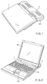
- FIG. 1 shows an outward appearance of an electronic apparatus system according to an embodiment of the present invention.
- the electronic apparatus system comprises an electronic apparatus 1, such as a notebook personal computer, and a fuel cell unit 2 which can be installed on and removed from the back of the electronic apparatus 1.
- the fuel cell unit 2 which is a power supply unit for supplying power to operate the electronic apparatus 1, includes a DMFC that causes methanol supplied as fuel to react with oxygen to produce electrical energy.
- Methanol, as fuel for the DMFC, is supplied from a cartridge fuel tank 2211 detachably housed in the fuel cell unit 2.
- FIG. 2 shows an outward appearance of the electronic apparatus system, with the top cover of the electronic apparatus opened.
- the top cover of the electronic apparatus 1 is provided on the body part by a hinge mechanism in such a manner that it can be opened and closed freely.
- a liquid crystal display (LCD) 141 is provided on its inner wall surface.
- LCD liquid crystal display
- a keyboard 151 for entering characters, symbols, and the like into the display screen appearing on the LCD 141
- a pointing device 152 for moving a mouse cursor displayed to point at a given place on the LCD 141 and pointing out a selection.
- FIG. 3 shows a schematic configuration of the electronic apparatus 1.
- a CPU 11, a RAM 12, an HDD 13, a display controller 14, a keyboard controller 15, and a power supply controller 16 are connected to a system bus.
- the CPU 11 which supervises control of the operation of the entire electronic apparatus 1, executes various types of programs, including an operating system, basic input/output system (BIOS), utility software, and application software stored in the RAM 12.
- BIOS basic input/output system
- a power supply management utility explained later is one of a plurality of utility software programs.
- the RAM 12 which is a storage medium acting as a main memory for the CPU 11, stores various programs executed by the CPU 11 and various types of data used in those programs.
- the HDD 13 which is a storage medium acting as an auxiliary memory for the electronic apparatus 1, stores various programs and various types of data in large amounts.
- the display controller 14, which is a device that handles the output side of a user interface provided by the electronic apparatus 1, performs control of the screen data processed by the CPU 11 so as to display the data on the LCD 141.
- the keyboard controller 15, which is a device that handles the input side of the user interface provided by the electronic apparatus 1, digitizes the operation of the keyboard 151 or pointing device 152 and transmits the result via an internal register to the CPU 11.
- the power supply controller 16 which supplies operating power to each section of the electronic apparatus 1, has the function of not only receiving power from the fuel cell unit 2 but also communicating with a microcomputer 21 (described later) of the fuel cell unit 2.
- the power supply controller 16 includes a register 161 for storing status information representing the state of the fuel cell unit 2. Referring to the status information, the power supply management utility can know the state of the fuel cell unit 2. As described later, the power supply management utility of the electronic apparatus system suitably displays a message peculiar to the DMFC.
- FIG. 4 shows a schematic configuration of the fuel cell unit 2.
- the fuel cell unit 2 has a microcomputer 21, a DMFC 22, an internal secondary cell 23, a charging circuit 24, an acceleration sensor 25, and an E2PROM 26.
- the microcomputer 21 which supervises control of the operation of the entire fuel cell unit 2, communicates with the power supply controller 16 of the electronic apparatus 1.
- the microcomputer 21 which also functions as a power supply controller in the fuel cell unit 21, performs control so as to supply the power of the internal secondary cell 23 to the DMFC 22 at the activation of the DMFC 22.
- the microcomputer 21 performs control so as to charge the internal secondary cell 23 with the power of the DMFC 22.
- the DMFC 22 is composed of a fuel tank slot 221, a fuel pump 222, a mixing tank 223, a liquid supply pump 224, a DMFC cell stack 225, and an air supply pump 226.
- the fuel tank slot 221 which is a slot for housing a cartridge fuel tank 2211 in such a manner that the tank 2211 can be installed and removed freely, has an installation and removal sensor 2212 for detecting the presence or absence of the installation of the fuel cell tank 2211.
- Methanol in the fuel cell tank 2211 housed in the fuel cell tank slot 221 is fed to the mixing tank 223.
- the methanol is diluted to, for example, 10% concentration by the water fed back from the DMFC cell stack 225.
- the mixing tank 223, which holds the dilute methanol, has a liquid level sensor 2231 for sensing whether or not the amount of the liquid falls in a suitable amount range. It is assumed that 15 to 90% of the holding capacity of the mixing tank 223 is within the suitable amount range.
- the microcomputer 21 determines that some abnormality has occurred.
- the mixing tank 223 has the function of vaporizing the unnecessary part of the water returned from the DMFC cell stack 225, thereby discharging the unnecessary water outside the DMFC 22.
- the liquid supply pump 224 feeds the methanol in the mixing tank 223 to the DMFC cell stack 225.
- the air taken in by the air supply pump 226 is fed.
- the methanol fed by the liquid supply pump 224 reacts with oxygen in the air fed by the air supply pump 226 in the DMFC cell stack 225, thereby generating power supplied to the electronic apparatus 1.
- water is also produced. This water is returned to the mixing tank 223 through a return flow path.
- the DMFC cell stack 225 has a temperature sensor 2251 for sensing whether or not the temperature in the stack falls in a suitable temperature range. It is assumed that the suitable temperature in the DMFC cell stack 225 at the activation of the DMFC 22 is 5 to 40°C and the suitable temperature in the DMFC cell stack 225 during the operation of the DMFC 22 is 50 to 90°C. At the start-up of the DMFC 22 and during its operation, the microcomputer 21 monitors whether or not the temperature in the stack falls in the respective suitable temperature ranges.
- the internal secondary cell 23 which is a lithium ion cell that can be charged and discharged repeatedly, supplies power needed by an auxiliary mechanism, including the fuel pump 222, liquid supply pump 224, and air supply pump 225, during the time from when the DMFC 22 starts to operate until more than a specific amount of power is generated.
- the internal secondary cell 23 may be charged by the charging circuit 24 under the control of the microcomputer 21 by using the power generated by the DMFC 22.
- the acceleration sensor 25 is a sensor for sensing whether or not the inclination of the fuel cell unit 2 is in a permitted angle range. It is assumed that the permitted range is an inclination of 30 degrees or less. If this range has been exceeded, the microcomputer 21 determines that a warning to the user is necessary.
- the E2PROM 26 is a memory device for storing status information indicating the state of the fuel cell unit 2.
- the microcomputer 21 records various states detected by various sensors, including the installation and removal sensor 2212, liquid level sensor 2231, temperature sensor 2251, and acceleration sensor 25, into the E2PROM 26 in the form of status information.
- the microcomputer 21 has the function of computing the remaining amount of fuel in the fuel tank 2211 according to the operating state of the DMFC 22.
- the microcomputer 21 also records the computed remaining amount into the E2PROM 26.
- the microcomputer 21 monitors whether or not the auxiliary mechanism, including the fuel pump 222, liquid supply pump 224, and air supply pump 226, is operating properly. For example, if the auxiliary mechanism has stopped abnormally, the microcomputer 21 records this as status information.
- the power supply controller 16 on the electronic apparatus 1 side For the power supply controller 16 on the electronic apparatus 1 side to be able to refer to the area of the E2PROM 26 in which the status information is stored, the interface for the area is opened. The power supply controller 16 reads the status information from the E2PROM 26 and stores it into the built-in register 161.
- the power supply management utility which operates under the control of the operating system, instructs the power supply controller 16 by way of the BIOS to read the status information stored in the E2PROM 26 at regular intervals of time. Then, the latest status information is stored in the register 161 of the power supply controller 16. As soon as the power supply management utility receives a reading end notice from the power supply controller 16, it acquires the status information in the register 161 by way of the BIOS.
- the power supply management utility can determine whether or not the fuel tank 2211 has been installed. If the fuel tank 2211 has not been installed, the power supply management utility displays a message to prompt the user to install the fuel tank 2211.
- FIG. 5 shows an example of a message given by the power supply management utility.
- buttons which enable the application software programs A and B to be called easily by click operations are displayed.
- an area called a task tray is secured.
- icons for indicating the state of resident programs running in the background are displayed. Therefore, this area is also called an indicator area.
- the icon for the power supply management utility is displayed in the task tray.
- the power supply management utility whose icon is displayed in the task tray requests the operating system to display the message "Install the fuel tank” in text-balloon form. Receiving the request, the operating system displays the message on the icon for the power supply management utility in the form as shown in FIG. 5. This realizes the display of a fuel tank installation request in the form of a message peculiar to the fuel cell unit 2.
- the fuel time 2211 is removed, a sufficient amount of dilute methanol is left in the mixing tank 223 of the DMFC 22. Therefore, for the time being, it is possible to continue supplying power to the electronic apparatus 1.
- the electronic apparatus system if its operation is continued in the present state, to display a message with good timing to indicate that the fuel has decreased to zero, the remaining amount of fuel in the fuel tank 2211 stored in the E2PROM 26 is forced to be updated to a previously specified proper value, when the microcomputer 21 of the fuel cell unit 2 has found from the installation and removal sensor 2212 that the fuel tank 2211 has been removed. This value can be calculated from the standard amount of liquid and the dilution of methanol in the mixing tank 223 during the operation of the DMFC 22 and the holding capacity of the fuel tank 2211.
- the power supply management utility can determine the remaining amount of fuel in the fuel tank 22. If the remaining amount of fuel in the fuel tank 2211 has decreased below a specific amount, the power supply management utility displays a massage to prompt the user to replace the fuel tank 2211 as shown in FIG. 6.
- the specific amount serving as the decision criterion should be set a value equal to or less than 10% of the holding capacity of the fuel cell 2211. This value, however, may be set arbitrarily by the power supply management utility.
- the power supply management utility When the occurrence of such an abnormality is detected, the power supply management utility requests the operating system to carry out, for example, a shutdown process, depending on the degree of importance. If such a serious abnormality as needs the execution of the shutdown process has occurred, the power supply management utility requests the operating system to makes a window display of a message as shown in FIG. 7 having a greater warning effect on the user, not a text-balloon display as shown in FIGS. 5 and 6.
- the message shown in FIG. 7 informs the user that the system is shut down.
- the power supply management utility requests the operating system to execute the shutdown process immediately.
- the power supply management utility automatically requests the operating system to execute the shutdown process.
- the power supply management utility displays an error code representing its contents together with a message to warn of the occurrence of an abnormality, as shown in FIG. 8. Then, when any other process is needed in place of the shutdown process, the power supply management utility requests the operating system to execute the process.
- the electronic apparatus system displays a message about the occurrence of an abnormality and automatically executes a process to cope with the abnormality.
- the operating system which supervises the resource management of the personal computer, also can manage the remaining power of the battery.
- the state where the battery remaining power has decreased to the level that cannot assure the operation from a hardware viewpoint is defined as battery remaining power 0%.
- the operating system recognizes battery remaining power 0%, it executes the shutdown process.
- the power supply management utility acquires the remaining amount of fuel in the fuel cell unit 2 from the power supply controller 16 and informs the operating system of the remaining amount. Therefore, in a case where the fuel has decreased to zero, the power supply management utility requests the operating system to carry out the shutdown process, when receiving notice that the fuel cell unit 2 has dropped to the battery remaining power 0%.
- the power supply management utility informs the operating system of a value smaller than the actual value by adding, for example, a 2% offset to the actual one, instead of informing the operating system of the remaining amount of fuel in the fuel tank 2211 shown in the status information acquired from the power supply controller 16.
- the microcomputer 21 informs the power supply controller 16 of the electronic apparatus 1 of the value obtained by subtracting 2% from the value stored in the E2PROM 26.
- the power supply controller 16 informs the CPU 11 of an interrupt and the remaining amount of fuel.
- the operating system is informed of the remaining amount smaller than the actual amount. Therefore, even when the operating system recognizes 0%, the 2% remaining amount is left in the mixing tank 223. With the 2% remaining amount, the shutdown process of the electronic apparatus 1 can be carried out. While the power supply controller 16 has notified the remaining amount, the operating system may read information about the remaining amount periodically.
- FIG. 9 is a flowchart for the procedure for message display control executed at the electronic apparatus system.
- the power supply management utility acquires the status information stored in the E2PROM 26 of the fuel cell unit 2 periodically by way of the power supply controller 16 and checks whether or not an abnormality has occurred in the fuel cell unit 2 (step A1). If an abnormality has occurred (YES in step A1), the power supply management utility determines whether or not the abnormality is of such a high degree of importance that a shutdown process is needed (step A2). If a shutdown process is needed (YES in step A2), the power supply management utility displays a message to prompt a shutdown process (step A3) and then requests the operating system to execute a shutdown process (step A4).
- step A2 If a shutdown process is not needed (NO in step A2), the power supply management utility displays a message to warn of the occurrence of an abnormality (step A5). If any measure has to be taken (YES in step A6), the power supply management utility requests the operating system to execute the process (step A7).
- step A1 determines whether or not the cartridge fuel tank 2211 has been removed (step A8). If it has been removed (YES in step A8), the power supply management utility displays a message to prompt the user to install the fuel tank 2211 (step A9). If it has not been removed (NO in step A8), the power supply management utility then determines whether or not the remaining amount of fuel has dropped below a specific amount (step A10). If it has dropped below the specific amount (YES in step A10), the power supply management utility displays a message to prompt the user to replace the fuel tank 2211 (step A11).
- the power supply management utility running on the electronic apparatus 1 side has acquired periodically the status information stored in the E2PROM 26 of the fuel cell unit 2. Instead, when the microcomputer 21 of the fuel cell unit 2 updates the status information, it may inform the power supply controller 16 of the electronic apparatus 1 of the update. In this case, the power supply controller 16 not only reads the latest status information from the E2PROM 26 and stores it in the built-in register 161 but also informs the CPU 11 of an interrupt and notifies the power supply management utility of the update of the status information. Then, being informed of the update of the status information, the power supply management utility acquires the latest status information stored in the register 161 of the power supply controller 16 by way of the BIOS.
Landscapes
- Life Sciences & Earth Sciences (AREA)
- Engineering & Computer Science (AREA)
- Sustainable Development (AREA)
- Sustainable Energy (AREA)
- Chemical & Material Sciences (AREA)
- Chemical Kinetics & Catalysis (AREA)
- Electrochemistry (AREA)
- General Chemical & Material Sciences (AREA)
- Manufacturing & Machinery (AREA)
- Fuel Cell (AREA)
Abstract
Description
Claims (12)
- An electronic apparatus characterized by comprising:a body (1);a display unit (141) provided on the body;a fuel cell unit (2) having a fuel cell (22) capable of supplying electric power to the body and a tank for the fuel cell;a sensing unit (21) which senses a remaining amount of fuel in the tank; anda control unit (11) which causes the display unit to display the remaining amount of fuel sensed by the sensing unit.
- The electronic apparatus according to claim 1, characterized in that the control unit causes the display unit to display information to prompt a replacement of the tank or information that the remaining amount has decreased below a predetermined value, when the remaining amount of fuel sensed by the sensing unit has decreased below the predetermined value.
- An electronic apparatus characterized by comprising:a body (1);a display unit (141) provided on the body;a fuel cell unit (2) having a fuel cell (22) capable of supplying electric power to the body and an installation portion in which a tank for the fuel cell can be installed;a sensing unit (2212) which senses whether or not the tank has been installed in the installation portion; anda control unit (11) which causes the display unit to display information to prompt an installation of the tank or information that the fuel cell has not been installed, when the sensing unit has sensed that the tank has not been installed.
- An electronic apparatus characterized by comprising:a body (1);a display unit (141) provided on the body;a fuel cell unit (2) having a fuel cell (22) capable of supplying electric power to the body and in and from which a tank (2211) for the fuel cell can be installed and removed;a sensing unit (2231,2251) which senses whether or not an abnormality has occurred in the fuel cell unit; anda control unit (11) which causes the display unit to display information of the occurrence of an abnormality, when the sensing unit has sensed that an abnormality has occurred in the fuel cell unit.
- The electronic apparatus according to claim 4, characterized by further comprising an abnormality processing unit which carries out a process corresponding to the abnormality.
- The electronic apparatus according to claim 5, characterized in that the control unit causes the display unit to display information that the'body is to be shut down when a predetermined abnormality has occurred in the fuel cell, and
the abnormality processing unit shuts down the body after a predetermined time has elapsed since the display of information by the control unit. - The electronic apparatus according to claim 4, characterized in that the fuel cell unit includes a storage portion (26) which stores status information indicating at least one of the presence or absence of the installation of the tank, the remaining amount of fuel in the tank, and the presence or absence of the occurrence of an abnormality in the fuel cell unit.
- The electronic apparatus according to claim 7, characterized by further comprising an informing unit which informs the sensing unit of the storage of the status information, when the status information has been stored in the storage portion, wherein
the sensing unit reads the status information stored in the storage portion, when being informed by the informing unit. - The electronic apparatus according to claim 7, characterized in that the sensing unit reads the status information stored in the storage portion, at predetermined intervals of time.
- The electronic apparatus according to claim 7, characterized in that the fuel cell unit has updating portion which updates the status information stored in the storage portion so as to indicate that the remaining amount of fuel is a predetermined amount, when the tank has been removed or when the remaining amount of fuel in the tank has been reduced to zero.
- A state display control method for an electronic apparatus capable of operating on electric power supplied from a fuel cell unit which has a fuel cell and in and from which a tank can be installed and removed, the method characterized by comprising the steps of:acquiring (A10) the remaining amount of fuel in the tank installed in the fuel cell unit;informing an operating system run on the electronic apparatus of the value obtained by subtracting a first predetermined value from the remaining amount acquired; anddisplaying (A11) information to prompt the replacement of the tank, when the value obtained by subtracting the first predetermined value from the remaining amount is smaller than a second predetermined value.
- A state display control method for an electronic apparatus capable of operating on electric power supplied from a fuel cell unit which has a fuel cell and in and from which a tank can be installed and removed, the method characterized by comprising the steps of:sensing (A8) the removal of the tank from the fuel cell unit;displaying (A9) information to prompt the installation of the tank, when the removal of the tank has been sensed; andinforming an operating system run on the electronic apparatus that the remaining amount of fuel is a predetermined amount, when the removal of the tank has been sensed.
Applications Claiming Priority (2)
| Application Number | Priority Date | Filing Date | Title |
|---|---|---|---|
| JP2003057466 | 2003-03-04 | ||
| JP2003057466A JP3713493B2 (en) | 2003-03-04 | 2003-03-04 | Electronic device, computer, and status display control method |
Publications (2)
| Publication Number | Publication Date |
|---|---|
| EP1455403A2 true EP1455403A2 (en) | 2004-09-08 |
| EP1455403A3 EP1455403A3 (en) | 2006-05-17 |
Family
ID=32821185
Family Applications (1)
| Application Number | Title | Priority Date | Filing Date |
|---|---|---|---|
| EP04004862A Withdrawn EP1455403A3 (en) | 2003-03-04 | 2004-03-02 | Electronic apparatus, and state display control method |
Country Status (3)
| Country | Link |
|---|---|
| US (1) | US20040224199A1 (en) |
| EP (1) | EP1455403A3 (en) |
| JP (1) | JP3713493B2 (en) |
Cited By (3)
| Publication number | Priority date | Publication date | Assignee | Title |
|---|---|---|---|---|
| WO2007122778A1 (en) * | 2006-04-25 | 2007-11-01 | Canon Kabushiki Kaisha | Fuel cartridge and fuel cell |
| WO2007094878A3 (en) * | 2005-11-29 | 2008-04-03 | Symbol Technologies Inc | Methods and apparatus for a hybrid power source |
| WO2012005810A1 (en) * | 2010-06-16 | 2012-01-12 | Apple Inc. | Fuel cell powered portable computing device with bidirectional communication link there between |
Families Citing this family (5)
| Publication number | Priority date | Publication date | Assignee | Title |
|---|---|---|---|---|
| JP2006252954A (en) * | 2005-03-10 | 2006-09-21 | Fujitsu Ltd | FUEL CELL DEVICE, ITS CONTROL METHOD, AND ELECTRONIC DEVICE |
| DE102005027651A1 (en) * | 2005-06-15 | 2006-12-21 | Robert Bosch Gmbh | Fuel cell system for e.g. vehicle, heating system, has consumption-optimizing unit which monitors fill level of fuel tank in order to monitor energy supply and/or energy demand with respect to consumer unit |
| JP4749088B2 (en) | 2005-08-26 | 2011-08-17 | 三洋電機株式会社 | Operation method of fuel cell power generator |
| TW200743240A (en) * | 2006-05-04 | 2007-11-16 | Syspotek Corp | Fuel cell with power management |
| JP2008021565A (en) * | 2006-07-14 | 2008-01-31 | Yamaha Motor Co Ltd | Fuel cell system and operation method thereof |
Family Cites Families (10)
| Publication number | Priority date | Publication date | Assignee | Title |
|---|---|---|---|---|
| EP0788172B1 (en) * | 1996-02-05 | 2001-12-05 | Matsushita Electric Industrial Co., Ltd. | Fuel cell for mounting on equipment |
| EP0813264A3 (en) * | 1996-06-14 | 2004-02-25 | Matsushita Electric Industrial Co., Ltd. | Fuel cell system, fuel feed system for fuel cell and portable electric appliance |
| US6228519B1 (en) * | 1997-10-06 | 2001-05-08 | Reveo, Inc. | Metal-air fuel cell battery systems having mechanism for extending the path length of metal-fuel tape during discharging and recharging modes of operation |
| US6383670B1 (en) * | 1999-10-06 | 2002-05-07 | Idatech, Llc | System and method for controlling the operation of a fuel processing system |
| US6522955B1 (en) * | 2000-07-28 | 2003-02-18 | Metallic Power, Inc. | System and method for power management |
| US20030010115A1 (en) * | 2001-07-16 | 2003-01-16 | Kelley Ronald J. | Means for measuring the liquid level in a reservoir for a fuel cell |
| US6713201B2 (en) * | 2001-10-29 | 2004-03-30 | Hewlett-Packard Development Company, L.P. | Systems including replaceable fuel cell apparatus and methods of using replaceable fuel cell apparatus |
| US7169489B2 (en) * | 2002-03-15 | 2007-01-30 | Fuelsell Technologies, Inc. | Hydrogen storage, distribution, and recovery system |
| JP3830910B2 (en) * | 2003-03-04 | 2006-10-11 | 株式会社東芝 | Fuel cell unit and status display control method |
| US20040219398A1 (en) * | 2003-05-02 | 2004-11-04 | Calhoon John C. | Fuel cell control and data reporting |
-
2003
- 2003-03-04 JP JP2003057466A patent/JP3713493B2/en not_active Expired - Fee Related
-
2004
- 2004-03-02 EP EP04004862A patent/EP1455403A3/en not_active Withdrawn
- 2004-03-03 US US10/791,274 patent/US20040224199A1/en not_active Abandoned
Cited By (10)
| Publication number | Priority date | Publication date | Assignee | Title |
|---|---|---|---|---|
| WO2007094878A3 (en) * | 2005-11-29 | 2008-04-03 | Symbol Technologies Inc | Methods and apparatus for a hybrid power source |
| WO2007122778A1 (en) * | 2006-04-25 | 2007-11-01 | Canon Kabushiki Kaisha | Fuel cartridge and fuel cell |
| US8071257B2 (en) | 2006-04-25 | 2011-12-06 | Canon Kabushiki Kaisha | Fuel cartridge and fuel cell |
| WO2012005810A1 (en) * | 2010-06-16 | 2012-01-12 | Apple Inc. | Fuel cell powered portable computing device with bidirectional communication link there between |
| CN102870261A (en) * | 2010-06-16 | 2013-01-09 | 苹果公司 | Fuel cell powered portable computing device |
| AU2011276993B2 (en) * | 2010-06-16 | 2014-06-26 | Apple Inc. | Fuel cell powered portable computing device with bidirectional communication link there between |
| US8980491B2 (en) | 2010-06-16 | 2015-03-17 | Apple Inc. | Fuel cell system to power a portable computing device |
| CN102870261B (en) * | 2010-06-16 | 2016-07-13 | 苹果公司 | For the fuel cell system that portable computing device is powered |
| US9917340B2 (en) | 2010-06-16 | 2018-03-13 | Apple Inc. | Fuel cell system to power a portable computing device |
| US10790561B2 (en) | 2010-06-16 | 2020-09-29 | Apple Inc. | Portable computing device for external fuel cell control |
Also Published As
| Publication number | Publication date |
|---|---|
| US20040224199A1 (en) | 2004-11-11 |
| JP2004265833A (en) | 2004-09-24 |
| JP3713493B2 (en) | 2005-11-09 |
| EP1455403A3 (en) | 2006-05-17 |
Similar Documents
| Publication | Publication Date | Title |
|---|---|---|
| US7569295B2 (en) | Fuel cell unit and state display control method | |
| EP1455403A2 (en) | Electronic apparatus, and state display control method | |
| US20040183501A1 (en) | Electronic apparatus, electronic system, and method of controlling operation of the same | |
| US7216246B2 (en) | Electronic apparatus and supply power setting method for the apparatus | |
| JP3764429B2 (en) | Electronic device and power supply switching control method for electronic device | |
| CN1319198C (en) | Electronic device and its using control method | |
| JP3720024B2 (en) | Electronic device system and operation control method | |
| US20050031916A1 (en) | Electronic apparatus, fuel tank unit, and method of controlling a power supply for the electronic apparatus | |
| JP3713495B2 (en) | Electronic device, fuel cell unit, and operation control method of electronic device | |
| CN100386710C (en) | Electronic equipment, battery unit and working mode switching method | |
| TWI445240B (en) | Fuel cell system and control method therefor | |
| US20050048330A1 (en) | Electronic system and power supply method | |
| JP4585475B2 (en) | Fuel cell unit | |
| JP2006048681A (en) | Electronic device and status display control method | |
| JP2003077510A (en) | Electronics | |
| JPH0742201Y2 (en) | Electronics | |
| KR101070629B1 (en) | Power supply system for portable electronic devices and control method thereof | |
| JPH07319589A (en) | Computer system | |
| CN118567460A (en) | Electronic system and power supply control method thereof | |
| JP2005235784A (en) | Electronic device system and operation control method | |
| JP2009087747A (en) | Electronics |
Legal Events
| Date | Code | Title | Description |
|---|---|---|---|
| PUAI | Public reference made under article 153(3) epc to a published international application that has entered the european phase |
Free format text: ORIGINAL CODE: 0009012 |
|
| 17P | Request for examination filed |
Effective date: 20040302 |
|
| AK | Designated contracting states |
Kind code of ref document: A2 Designated state(s): AT BE BG CH CY CZ DE DK EE ES FI FR GB GR HU IE IT LI LU MC NL PL PT RO SE SI SK TR |
|
| AX | Request for extension of the european patent |
Extension state: AL LT LV MK |
|
| PUAL | Search report despatched |
Free format text: ORIGINAL CODE: 0009013 |
|
| AK | Designated contracting states |
Kind code of ref document: A3 Designated state(s): AT BE BG CH CY CZ DE DK EE ES FI FR GB GR HU IE IT LI LU MC NL PL PT RO SE SI SK TR |
|
| AX | Request for extension of the european patent |
Extension state: AL LT LV MK |
|
| AKX | Designation fees paid |
Designated state(s): DE FR GB |
|
| 17Q | First examination report despatched |
Effective date: 20100212 |
|
| STAA | Information on the status of an ep patent application or granted ep patent |
Free format text: STATUS: THE APPLICATION IS DEEMED TO BE WITHDRAWN |
|
| 18D | Application deemed to be withdrawn |
Effective date: 20100623 |