EP1455361A1 - An access for a computer housing - Google Patents
An access for a computer housing Download PDFInfo
- Publication number
- EP1455361A1 EP1455361A1 EP03020337A EP03020337A EP1455361A1 EP 1455361 A1 EP1455361 A1 EP 1455361A1 EP 03020337 A EP03020337 A EP 03020337A EP 03020337 A EP03020337 A EP 03020337A EP 1455361 A1 EP1455361 A1 EP 1455361A1
- Authority
- EP
- European Patent Office
- Prior art keywords
- access
- door
- disk drive
- housing
- actuator
- Prior art date
- Legal status (The legal status is an assumption and is not a legal conclusion. Google has not performed a legal analysis and makes no representation as to the accuracy of the status listed.)
- Withdrawn
Links
Images




Classifications
-
- G—PHYSICS
- G06—COMPUTING OR CALCULATING; COUNTING
- G06F—ELECTRIC DIGITAL DATA PROCESSING
- G06F1/00—Details not covered by groups G06F3/00 - G06F13/00 and G06F21/00
- G06F1/16—Constructional details or arrangements
- G06F1/18—Packaging or power distribution
- G06F1/181—Enclosures
-
- G—PHYSICS
- G11—INFORMATION STORAGE
- G11B—INFORMATION STORAGE BASED ON RELATIVE MOVEMENT BETWEEN RECORD CARRIER AND TRANSDUCER
- G11B17/00—Guiding record carriers not specifically of filamentary or web form, or of supports therefor
- G11B17/02—Details
- G11B17/04—Feeding or guiding single record carrier to or from transducer unit
- G11B17/0401—Details
- G11B17/0405—Closing mechanism, e.g. door
-
- G—PHYSICS
- G11—INFORMATION STORAGE
- G11B—INFORMATION STORAGE BASED ON RELATIVE MOVEMENT BETWEEN RECORD CARRIER AND TRANSDUCER
- G11B33/00—Constructional parts, details or accessories not provided for in the other groups of this subclass
- G11B33/02—Cabinets; Cases; Stands; Disposition of apparatus therein or thereon
- G11B33/027—Covers
-
- G—PHYSICS
- G11—INFORMATION STORAGE
- G11B—INFORMATION STORAGE BASED ON RELATIVE MOVEMENT BETWEEN RECORD CARRIER AND TRANSDUCER
- G11B33/00—Constructional parts, details or accessories not provided for in the other groups of this subclass
- G11B33/12—Disposition of constructional parts in the apparatus, e.g. of power supply, of modules
- G11B33/121—Disposition of constructional parts in the apparatus, e.g. of power supply, of modules the apparatus comprising a single recording/reproducing device
- G11B33/123—Mounting arrangements of constructional parts onto a chassis
Definitions
- Embodiments of the present invention relate to the field of access doors in a computer housing. Specifically, embodiments of the present invention relate to access doors for connectors and optical drive units.
- Personal computers are in wide use today and one popular style is the desktop computer that is mounted in a housing that occupies a relatively small space on a desktop.
- Some desktop computers are configured vertically, also known as a ''tower'' configuration.
- the tower configuration which occupies desk space in addition to space for a monitor, also lends itself to being stored on the floor under a desk, thereby freeing up desk space.
- Some personal computers are configured horizontally, thereby occupying a larger amount of desk space than the tower configuration but allowing for a monitor to be located on its top.
- disk drives e.g., optical disk drives
- the disk drives generally provide disk access via ejectable drawers that eject through an opening in the computer housing.
- a typical tower configuration may have one or more optical disk drive drawers that open through the front of the housing and a lift-up door behind which the various connectors are available.
- Personal computers may often be found in industrial settings, such as test areas in manufacturing facilities. Such settings frequently are subjected to a large amount of airborne dust and/or other pollutants. Such pollutants can be detrimental to the mechanisms of disk drives, and can lead to drive failures.
- Tower computers are often located on the floor underneath a user's desk. This location makes access the connectors for connecting peripheral equipment quite difficult, particularly with doors that must be lifted for access to the connectors. In addition, the lift-up doors block a users visual access to the connectors from a position above the access door.
- An access in a housing for a computer has a pivot mechanism coupled to the housing, and a door coupled to the pivot mechanism.
- the door rests flush against the computer housing when the access is not deployed.
- the door is configured to pivot in a downward direction for deployment of the access.
- An actuator is coupled to the door for actuating an ejection mechanism in a disk drive drawer.
- the actuator has a foam pad for depressing an eject button on a faceplate of the disk drive drawer.
- Embodiments of the present invention include downward pivoting access doors coupled to a computer housing that provide access to disk drives and connectors.
- an access door for a disk drive drawer rests flush against a computer housing when not in use and has a pivot mechanism that is configured to pivot downward as the disk drive drawer opens.
- An actuator coupled to the door actuates an ejection mechanism in the disk drive drawer when a foam pad coupled to the actuator depresses an eject button on a faceplate of the disk drive drawer.
- Providing disk drive access doors as a feature of a computer housing has an advantage of providing a barrier to airborne pollutants that can be present in industrial environments such as manufacturing facilities and construction sites.
- having access doors as a feature of the computer housing provides an economic advantage of allowing standard disk drive units, having standard color, configuration and texture of faceplates, to be used, thereby avoiding the expense of customizing disk drive unit faceplates for a particular design of housing.
- providing downward opening doors for concealing connectors allows readily visible access to the connectors. This is particularly useful in instances where the computer is stored on the floor.
- providing labels to indicate the location of available connectors further enables a user to quickly locate and install connections for peripheral accesses.
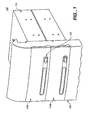
- Figure 1 is an upper right perspective view 100 of a top potion of a computer housing 105 with disk drives 115 attached, illustrating identical disk drive access doors 110a and 110b concealing faceplates of the disk drive drawers, in accordance with one embodiment.
- view 100 is of a tower configuration for a personal computer housing, it should be understood that the present invention can be implemented in a horizontal configuration or any other configuration that accommodates disk drives.
- computer housing 105 is shown in the present embodiment as having two identical disk drive access doors 110a and 110b it should also be understood that there can be a single access door 110a or 110 b, or there can be more than two disk drive access doors.
- an eject button 120 is located on the front of each access door 100a and 100b.eject button 120 is coupled to an actuator (see Figure 4) that actuates an ejection mechanism for opening a drawer in the disk drive unit 115 which, in turn, opens access door 110a, according to one embodiment of the present invention.
- access doors 110a and 110b as a feature of computer housing 105 has an advantage of providing a barrier to airborne pollutants that are often present in industrial environments such as manufacturing facilities and construction sites.
- having access doors 110a and 110b as a feature of computer housing 105 provides an economic advantage of allowing standard disk drive units, having standard color, configuration and texture of faceplates, to be used, thereby avoiding the expense of customizing disk drive unit faceplates for a particular design of housing.
- Figure 2 illustrates an interior view 200 of a disk drive access door 110a, according to one embodiment.
- the back side of eject button 120 is shown.
- An actuator 420 is located on housing 105 beneath the opening for ejecting a disk drive drawer.
- eject button 120 can align with actuator 420 so that pressing eject button 120 in turn presses actuator 420.
- Hinge pin 210 functions to couple access door 110a to housing 105, and it also functions as an axis for door spring 220.
- Door spring 220 is configured so that its tension maintains access door 110a in a closed position until overcome by a force pressing outward from the inside of access door 110a.
- Ramp 310 and its compliment furnish a platform on which the faceplate of a disk drive drawer ejecting from its housing can press to open access door 110a.
- ramp 310 is shown to be located on one side of the interior of door 110a, with a complimentary ramp on the opposite side, it should be understood that a single ramp, or any number of ramps may be employed and positioned as convenient.
- Figure 3A is a right front view 300a of computer housing 105 illustrating the functioning of disk drive access doors 110a and 110b, according to one embodiment.
- Figure 3B is a right side view 300b of computer housing 105 illustrating the functioning of disk drive access doors 110a and 110b, according to one embodiment.
- Figure 3A will be discussed in concert with 3B for describing an access door functionality. In both figures, the access doors are shown opening as disk drive drawers 320a and 320 b open.
- Disk drive drawer 320a is shown partially open as it emerges from its housing. Disk drive drawer 320b is depicted in a fully open position. As disk drive drawer opens, faceplate 330 presses on ramp 310 of access door 110a, overcoming the tension of door spring 220 (as shown in Figure 2), and causing access door 110a to pivot out and downward. As the disk drive drawer 320a continues to open, the lower edge of faceplate moves along ramp 31, causing access door 110a to continue pivoting open until the lower edge of faceplate 330 reaches the zenith 340 of ramp 310.
- access door 110b and disk drive drawer 320b of Figure 3B As shown by access door 110b and disk drive drawer 320b of Figure 3B, in accordance with one embodiment, as disk drive drawer 320b continues to open, the lower edge of faceplate 340 moves past zenith 340 and continues pressing against an outer downward feature 350 of ramp 310. The tension on door spring 220 causes access door 110b to begin to pivot upward under disk drive drawer 320b. Thus, access door 310a may open to a maximum position when disk drawer 320a is at a partially open position and access door 110b may be open at a lesser position when disk drawer 320a is fully open.
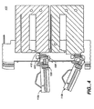
- FIG. 4 a cutaway side view 400 of access doors 110a and 110b is shown, illustrating an actuator mechanism for an eject function of a disk drive, in accordance with one embodiment.
- Access door eject button 120 may be seen penetrating the thickness of access door 110a and 110b and emerging from both the front and the back sides of access door 110a and 110b. Thus, pressing on access door eject button 120 from one side causes it to further emerge from the other side.
- actuator 420 Also illustrated on Figure 4 are actuator 420, actuator spring 430 and foam pad 410 coupled to actuator 420 and to housing 105.
- Foam pad 410 can be coupled to actuator 420 by one of many adhesive substances suitable for the environment or be any other coupling method deemed appropriate.
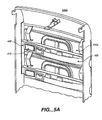
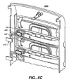
- Figure 4 can be further understood when viewed in concert with Figures 5A, 5B and 5C, and with flow diagram 600 of Figure 6.
- Figure 5A is a rear view 500a of housing 105, illustrating an actuator spring 430 and foam pad 410, according to one embodiment.
- Figure 5B is a cutaway view 500b illustrating a disk drive drawer eject button 510, located on disk drive unit 115 below faceplate 330, in relation to foam pad 410 of the actuator mechanism, in accordance with one embodiment.
- Figure 5C is an exploded view 500c of an actuator mechanism, illustrating foam pad 410, actuator spring 430, actuator 420 and the back side of access door eject button 120, in accordance with one embodiment.
- FIG. 6 is a flow diagram 600 of the steps in a process for opening and closing a disk drive access door, in accordance with one embodiment of the present invention.
- Process 600 is entered at step 610 when the eject button 120 in access door 110a is depressed, in turn depressing actuator 420, located on housing 105, in line with access door eject button 120 and the drive drawer eject button 510 of drive unit 115.
- disk drive unit 115 can be any standard disk drive unit having dimensions appropriate for the personal computer in which it is designated to reside and having an eject button 510 that aligns with actuator 420 and foam pad 410.
- the eject mechanism can be any eject mechanism that accompanies drive unit 115 and causes a disk drive drawer to emerge.
- step 630 in one embodiment, as access door eject button 120 is released, actuator spring 430 retracts, returning actuator 420 and foam pad 410 to their inactive position.
- the disk drive eject mechanism having been engaged, begins ejecting disk drive drawer 320.
- drive drawer 320 pushes against the ramp (e.g., ramp 310 of Figures 3A and 3B) of access door 110, overcoming tension of door spring 220, and causing access door 110 to pivot downward as drive drawer faceplate 330 moves along ramp 310.
- ramp e.g., ramp 310 of Figures 3A and 3B
- step 650 access door 110 reaches a maximum open position when the bottom edge of faceplate 330 reaches the zenith (e.g., 340 of Figure 3B) of ramp 310.
- the disk drive drawer 320 is not completely open.
- step 660 is entered.
- door spring 220 causes access drive door 110 to partially close beneath disk drive drawer 320 (see Figures 3A and 3B).
- Step 670 illustrates the access door function at the beginning of a door close phase.
- the disk drive drawer 320 is caused to close, either via a software command, by a user pressing on the faceplate 330 or by whatever method is used to close the drive unit, the bottom of faceplate 330 begins to move in a reverse direction, toward the drive unit housing 115.
- faceplate 330 traverses the outer downward feature 350 of ramp 310 toward zenith 340, causing access door 110 to pivot downward, opening to the maximum position, in accordance with one embodiment.
- disk drive drawer 320 continues to retract into drive unit housing 115, door spring 220 causes access door 110 to pivot upward.
- door spring 220 causes access door 110 to pivot upward.
- access door 110 assumes a closed position, flush with computer housing 105 and process 600 is exited.
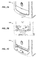
- Figure 7A depicts an exterior right front view 700a of a computer housing with a downward-pivoting door 710 for concealing connectors, in accordance with one embodiment.
- view 700 is of a tower configuration for a personal computer housing, it should be understood that the present invention can be implemented in a horizontal configuration or any other configuration that accommodates connectors.
- Tower computers are often located on the floor underneath a user's desk which can make access the connectors for connecting peripheral equipment quite difficult. Having a downward opening connector door 710 on the front of the computer housing 105 can provide ready visual and mechanical access to connectors within. Connector door 710 rests flush with computer housing 105 when closed, and can be opened by pulling out on tab 705.
- Figure 7B illustrates an open view 700b of downward-pivoting connector door 710 revealing connector 720 within, according to one embodiment.
- Connector 730 can be any of a variety of connectors used to connect a computer to peripheral devices or access peripheral services. Such devices can include, but are not limited to, for instance, USB connectors, Fire wire connectors, fiber optic connectors, coaxial connectors, or network connectors.
- Connector door 710 pivots downward on a plurality of hinges 715, and remains in an open position until closed by a user.
- Figure 7C illustrates an open view 700c of downward-pivoting connector door 710 having labels 730 showing locations of available connectors such as connector 720, according to one embodiment.
- the labels 730 provide an advantage of providing a user a pictorial diagram of the location of connectors to facilitate a connection process.
- the labels 730 may be a variety of representations, for example, a pictorial image of a connector, a connector name, a standard symbol for a connector or any other representation that would portray the available connectors.
- a plurality of snap devices 740 can function to maintain connector door 710 in a closed position when not in use.
Landscapes
- Engineering & Computer Science (AREA)
- Theoretical Computer Science (AREA)
- Computer Hardware Design (AREA)
- Power Engineering (AREA)
- Human Computer Interaction (AREA)
- Physics & Mathematics (AREA)
- General Engineering & Computer Science (AREA)
- General Physics & Mathematics (AREA)
- Casings For Electric Apparatus (AREA)
Abstract
Description
- Embodiments of the present invention relate to the field of access doors in a computer housing. Specifically, embodiments of the present invention relate to access doors for connectors and optical drive units.
- Personal computers are in wide use today and one popular style is the desktop computer that is mounted in a housing that occupies a relatively small space on a desktop. Some desktop computers are configured vertically, also known as a ''tower'' configuration. The tower configuration, which occupies desk space in addition to space for a monitor, also lends itself to being stored on the floor under a desk, thereby freeing up desk space. Some personal computers are configured horizontally, thereby occupying a larger amount of desk space than the tower configuration but allowing for a monitor to be located on its top.
- One common feature of most personal computers, no matter what configuration, is that they have disk drives (e.g., optical disk drives) and they have connectors for connecting to networks and to various peripheral devices. The disk drives, such as CD and DVD drives, generally provide disk access via ejectable drawers that eject through an opening in the computer housing. A typical tower configuration may have one or more optical disk drive drawers that open through the front of the housing and a lift-up door behind which the various connectors are available.
- Personal computers may often be found in industrial settings, such as test areas in manufacturing facilities. Such settings frequently are subjected to a large amount of airborne dust and/or other pollutants. Such pollutants can be detrimental to the mechanisms of disk drives, and can lead to drive failures.
- Additionally, the manufacturing of faceplates for drive drawers that are customized to fit the form, material and color of a given computer housing is very expensive. There are "off-the-shelf" drive drawers available with standard colored faceplates that are substantially less expensive than custom faceplates.
- Tower computers are often located on the floor underneath a user's desk. This location makes access the connectors for connecting peripheral equipment quite difficult, particularly with doors that must be lifted for access to the connectors. In addition, the lift-up doors block a users visual access to the connectors from a position above the access door.
- An access in a housing for a computer is disclosed. The access has a pivot mechanism coupled to the housing, and a door coupled to the pivot mechanism. The door rests flush against the computer housing when the access is not deployed. The door is configured to pivot in a downward direction for deployment of the access. An actuator is coupled to the door for actuating an ejection mechanism in a disk drive drawer. The actuator has a foam pad for depressing an eject button on a faceplate of the disk drive drawer.
-
- Figure 1 is an upper right perspective view of a top portion of a computer housing with disk drives attached, illustrating disk drive access doors concealing the faceplates of the disk drive drawers, in accordance with one embodiment of the present invention.
- Figure 2 illustrates an interior view of a disk drive access door, according to one embodiment of the present invention.
- Figure 3A is a right front view of a computer housing illustrating the functioning of disk drive access doors, according to one embodiment of the present invention.
- Figure 3B is a right side view of a computer housing illustrating the functioning of disk drive access doors, according to one embodiment of the present invention.
- Figure 4 is a
cutaway side view 400 of access doors, illustrating an actuator mechanism for an eject function of a disk drive, in accordance with one embodiment of the present invention. - Figure 5A is an illustration of an actuator spring and foam pad, according to one embodiment of the present invention.
- Figure 5B is an illustration of an eject button on a disk drive faceplate in relation to an actuator mechanism, in accordance with one embodiment of the present invention.
- Figure 5C is an exploded view of an actuator mechanism, in accordance with one embodiment of the present invention.
- Figure 6 is a flow diagram of the steps in a process for opening and closing a disk drive access door, in accordance with one embodiment of the present invention.
- Figure 7A depicts an exterior right front view of a housing with a downward pivoting door for concealing connectors, in accordance with one embodiment of the present invention.
- Figure 7B illustrates an open view of a downward pivoting connector door revealing connectors within, according to one embodiment of the present invention.
- Figure 7C illustrates an open view of a downward pivoting connector door having labels showing locations of available connectors, according to one embodiment of the present invention.
-
- Reference will now be made in detail to embodiments of the invention, examples of which are illustrated in the accompanying drawings. While the invention will be described in conjunction with the embodiments, it will be understood that they are not intended to limit the invention to these embodiments. On the contrary, the invention is intended to cover alternatives, modifications, and equivalents, which may be included within the spirit and scope of the invention as defined by the appended claims. Furthermore, in the following detailed description, numerous specific details are set forth in order to provide a thorough understanding of the present invention. In other instances, well known methods, procedures, and components have not been described in detail so as not to unnecessarily obscure aspects of the present invention.
- Embodiments of the present invention include downward pivoting access doors coupled to a computer housing that provide access to disk drives and connectors.
- In one embodiment, an access door for a disk drive drawer rests flush against a computer housing when not in use and has a pivot mechanism that is configured to pivot downward as the disk drive drawer opens. An actuator coupled to the door actuates an ejection mechanism in the disk drive drawer when a foam pad coupled to the actuator depresses an eject button on a faceplate of the disk drive drawer.
- Providing disk drive access doors as a feature of a computer housing has an advantage of providing a barrier to airborne pollutants that can be present in industrial environments such as manufacturing facilities and construction sites. In addition, having access doors as a feature of the computer housing provides an economic advantage of allowing standard disk drive units, having standard color, configuration and texture of faceplates, to be used, thereby avoiding the expense of customizing disk drive unit faceplates for a particular design of housing.
- In addition, providing downward opening doors for concealing connectors allows readily visible access to the connectors. This is particularly useful in instances where the computer is stored on the floor. In addition, providing labels to indicate the location of available connectors further enables a user to quickly locate and install connections for peripheral accesses.
- Certain portions of the detailed descriptions of embodiments of the invention, which follow, are presented in terms of processes and methods (e.g.,
process 600 of Fig. 6). Although specific steps are disclosed herein describing the operations of these processes and methods, such steps are exemplary. That is, embodiments of the present invention are well suited to performing various other steps or variations of the steps recited in the flowchart of the figure herein. - Figure 1 is an upper right perspective view 100 of a top potion of a
computer housing 105 withdisk drives 115 attached, illustrating identical diskdrive access doors view 100 is of a tower configuration for a personal computer housing, it should be understood that the present invention can be implemented in a horizontal configuration or any other configuration that accommodates disk drives. Althoughcomputer housing 105 is shown in the present embodiment as having two identical diskdrive access doors single access door - Still referring to Figure 1, an
eject button 120 is located on the front of each access door 100a and100b.eject button 120 is coupled to an actuator (see Figure 4) that actuates an ejection mechanism for opening a drawer in thedisk drive unit 115 which, in turn, opensaccess door 110a, according to one embodiment of the present invention. - The providing of
access doors computer housing 105 has an advantage of providing a barrier to airborne pollutants that are often present in industrial environments such as manufacturing facilities and construction sites. In addition, havingaccess doors computer housing 105 provides an economic advantage of allowing standard disk drive units, having standard color, configuration and texture of faceplates, to be used, thereby avoiding the expense of customizing disk drive unit faceplates for a particular design of housing. - Figure 2 illustrates an
interior view 200 of a diskdrive access door 110a, according to one embodiment. The back side ofeject button 120 is shown. Anactuator 420 is located onhousing 105 beneath the opening for ejecting a disk drive drawer. Whenaccess door 110a is in a closed position, ejectbutton 120 can align withactuator 420 so that pressingeject button 120 in turn pressesactuator 420. -
Hinge pin 210 functions to coupleaccess door 110a tohousing 105, and it also functions as an axis fordoor spring 220.Door spring 220 is configured so that its tension maintainsaccess door 110a in a closed position until overcome by a force pressing outward from the inside ofaccess door 110a.Ramp 310 and its compliment furnish a platform on which the faceplate of a disk drive drawer ejecting from its housing can press toopen access door 110a. - Although
ramp 310 is shown to be located on one side of the interior ofdoor 110a, with a complimentary ramp on the opposite side, it should be understood that a single ramp, or any number of ramps may be employed and positioned as convenient. - Figure 3A is a
right front view 300a ofcomputer housing 105 illustrating the functioning of diskdrive access doors right side view 300b ofcomputer housing 105 illustrating the functioning of diskdrive access doors disk drive drawers -
Disk drive drawer 320a is shown partially open as it emerges from its housing.Disk drive drawer 320b is depicted in a fully open position. As disk drive drawer opens,faceplate 330 presses onramp 310 ofaccess door 110a, overcoming the tension of door spring 220 (as shown in Figure 2), and causingaccess door 110a to pivot out and downward. As thedisk drive drawer 320a continues to open, the lower edge of faceplate moves along ramp 31, causingaccess door 110a to continue pivoting open until the lower edge offaceplate 330 reaches thezenith 340 oframp 310. - As shown by
access door 110b anddisk drive drawer 320b of Figure 3B, in accordance with one embodiment, asdisk drive drawer 320b continues to open, the lower edge offaceplate 340 moves pastzenith 340 and continues pressing against an outerdownward feature 350 oframp 310. The tension ondoor spring 220 causesaccess door 110b to begin to pivot upward underdisk drive drawer 320b. Thus, access door 310a may open to a maximum position whendisk drawer 320a is at a partially open position andaccess door 110b may be open at a lesser position whendisk drawer 320a is fully open. - Referring now to Figure 4, a
cutaway side view 400 ofaccess doors door eject button 120 may be seen penetrating the thickness ofaccess door access door door eject button 120 from one side causes it to further emerge from the other side. - Also illustrated on Figure 4 are actuator 420,
actuator spring 430 andfoam pad 410 coupled toactuator 420 and tohousing 105.Foam pad 410 can be coupled toactuator 420 by one of many adhesive substances suitable for the environment or be any other coupling method deemed appropriate. - Figure 4 can be further understood when viewed in concert with Figures 5A, 5B and 5C, and with flow diagram 600 of Figure 6. Figure 5A is a
rear view 500a ofhousing 105, illustrating anactuator spring 430 andfoam pad 410, according to one embodiment. Figure 5B is acutaway view 500b illustrating a disk drivedrawer eject button 510, located ondisk drive unit 115 belowfaceplate 330, in relation tofoam pad 410 of the actuator mechanism, in accordance with one embodiment. Figure 5C is an explodedview 500c of an actuator mechanism, illustratingfoam pad 410,actuator spring 430,actuator 420 and the back side of accessdoor eject button 120, in accordance with one embodiment. - Figure 6 is a flow diagram 600 of the steps in a process for opening and closing a disk drive access door, in accordance with one embodiment of the present invention.
Process 600 is entered atstep 610 when theeject button 120 inaccess door 110a is depressed, inturn depressing actuator 420, located onhousing 105, in line with accessdoor eject button 120 and the drivedrawer eject button 510 ofdrive unit 115. - As shown in
step 620 of Figure 6,actuator 420 moves toward the front ofdrive unit 115, extendingactuator spring 430, untilfoam pad 410 contacts and depresses drivedrawer eject button 510, located ondisk drive unit 115, thus activating the eject mechanism ofdisk drive unit 115, in accordance with one embodiment. It should be understood thatdisk drive unit 115 can be any standard disk drive unit having dimensions appropriate for the personal computer in which it is designated to reside and having aneject button 510 that aligns withactuator 420 andfoam pad 410. The eject mechanism can be any eject mechanism that accompaniesdrive unit 115 and causes a disk drive drawer to emerge. - As illustrated by
step 630, in one embodiment, as accessdoor eject button 120 is released,actuator spring 430 retracts, returningactuator 420 andfoam pad 410 to their inactive position. The disk drive eject mechanism, having been engaged, begins ejectingdisk drive drawer 320. - At
step 640 ofprocess 600, according to one embodiment, upon opening,drive drawer 320 pushes against the ramp (e.g., ramp 310 of Figures 3A and 3B) ofaccess door 110, overcoming tension ofdoor spring 220, and causingaccess door 110 to pivot downward asdrive drawer faceplate 330 moves alongramp 310. - As
process 600 moves to step 650,access door 110 reaches a maximum open position when the bottom edge offaceplate 330 reaches the zenith (e.g., 340 of Figure 3B) oframp 310. At this point, according to one embodiment, thedisk drive drawer 320 is not completely open. As disk drive drawer continues to open,step 660 is entered. - At
step 660, asfaceplate 330 continues to openpast zenith 340 oframp 310, along outerdownward feature 350 of ramp310,door spring 220 causes access drivedoor 110 to partially close beneath disk drive drawer 320 (see Figures 3A and 3B). - Step 670 illustrates the access door function at the beginning of a door close phase. When the
disk drive drawer 320 is caused to close, either via a software command, by a user pressing on thefaceplate 330 or by whatever method is used to close the drive unit, the bottom offaceplate 330 begins to move in a reverse direction, toward thedrive unit housing 115. In moving thusly,faceplate 330 traverses the outerdownward feature 350 oframp 310 towardzenith 340, causingaccess door 110 to pivot downward, opening to the maximum position, in accordance with one embodiment. - As the process moves to step 680,
disk drive drawer 320 continues to retract intodrive unit housing 115,door spring 220 causesaccess door 110 to pivot upward. Asdisk drive drawer 320 completes retracting and assumes a closed position indisk drive housing 115,access door 110 assumes a closed position, flush withcomputer housing 105 andprocess 600 is exited. - Figure 7A depicts an exterior right
front view 700a of a computer housing with a downward-pivotingdoor 710 for concealing connectors, in accordance with one embodiment. Although view 700 is of a tower configuration for a personal computer housing, it should be understood that the present invention can be implemented in a horizontal configuration or any other configuration that accommodates connectors. - Tower computers are often located on the floor underneath a user's desk which can make access the connectors for connecting peripheral equipment quite difficult. Having a downward
opening connector door 710 on the front of thecomputer housing 105 can provide ready visual and mechanical access to connectors within.Connector door 710 rests flush withcomputer housing 105 when closed, and can be opened by pulling out on tab 705. - Figure 7B illustrates an
open view 700b of downward-pivotingconnector door 710 revealingconnector 720 within, according to one embodiment.Connector 730 can be any of a variety of connectors used to connect a computer to peripheral devices or access peripheral services. Such devices can include, but are not limited to, for instance, USB connectors, Fire wire connectors, fiber optic connectors, coaxial connectors, or network connectors.Connector door 710 pivots downward on a plurality of hinges 715, and remains in an open position until closed by a user. - Figure 7C illustrates an
open view 700c of downward-pivotingconnector door 710 havinglabels 730 showing locations of available connectors such asconnector 720, according to one embodiment. Thelabels 730 provide an advantage of providing a user a pictorial diagram of the location of connectors to facilitate a connection process. Thelabels 730 may be a variety of representations, for example, a pictorial image of a connector, a connector name, a standard symbol for a connector or any other representation that would portray the available connectors. A plurality of snap devices 740 can function to maintainconnector door 710 in a closed position when not in use. - An embodiment of the present invention, a method and apparatus providing access in a computer housing, is thus described. While the present invention has been described in particular embodiments, it should be appreciated that the present invention should not be construed as limited by such embodiments, but rather construed according to the following claims and their equivalents.
Claims (9)
- In a housing (105) for a computer, an access comprising:a pivot mechanism (215) coupled to said housing (105);a door (110a or 110b) coupled to said pivot mechanism (210), wherein said door (110a or 110b rests flush against said computer housing (105) when said access is not deployed and wherein said door (110a or 110b) is configured to pivot in a downward direction for deployment of said access; andan actuator (420) coupled to said door (110a or 110b) for actuating an ejection mechanism (120) in a disk drive drawer (320a) within said housing (105), wherein said actuator (420) comprises a foam pad (410) for depressing a first eject button (510) on a faceplate of said disk drive drawer (320a).
- The access as recited in Claim 1, wherein said door (110a) covers said disk drive drawer (320a).
- The access as recited in Claim 2, wherein said door (110a) comprises a second eject button (120) for extending an actuator spring (430) and actuating said actuator.
- The access as recited in Claim 3 wherein releasing said second eject button (120) causes an actuator spring (430) to retract, deactivating said actuator.
- The access as recited in Claim 1 further comprising a ramp (310) coupled to said door (110a).
- The access as recited in Claim 5 wherein said ramp (310) comprises a zenith (340) and an outer downward feature (350).
- The access as recited in Claim 1, wherein said pivot mechanism (215) comprises:a plurality of hinges (225) coupled to a lower portion of said door (110a);a hinge pin (210) coupled to said plurality of hinges (225) and said housing (105); anda door spring (220) coupled to said hinge pin (210) for maintaining said door (110a) in a closed position when said access is not deployed.
- The access as recited in Claim 7 wherein said door (110a) is caused to pivot downward on said plurality of hinges (225) as said disk drive drawer (320a) emerges from a disk drive housing (115).
- The access as recited in Claim 8, wherein said door spring (220) functions to cause said door (110a) to pivot upward when said disk drive drawer (320a) retracts into said disk drive housing (115).
Applications Claiming Priority (2)
| Application Number | Priority Date | Filing Date | Title |
|---|---|---|---|
| US377686 | 2003-02-28 | ||
| US10/377,686 US6891720B2 (en) | 2003-02-28 | 2003-02-28 | Access for a computer housing |
Publications (1)
| Publication Number | Publication Date |
|---|---|
| EP1455361A1 true EP1455361A1 (en) | 2004-09-08 |
Family
ID=32824745
Family Applications (1)
| Application Number | Title | Priority Date | Filing Date |
|---|---|---|---|
| EP03020337A Withdrawn EP1455361A1 (en) | 2003-02-28 | 2003-09-09 | An access for a computer housing |
Country Status (2)
| Country | Link |
|---|---|
| US (1) | US6891720B2 (en) |
| EP (1) | EP1455361A1 (en) |
Cited By (1)
| Publication number | Priority date | Publication date | Assignee | Title |
|---|---|---|---|---|
| TWI478155B (en) * | 2010-12-10 | 2015-03-21 | Hon Hai Prec Ind Co Ltd | Hard disk drive door ejection mechanism and computer case therewith |
Families Citing this family (18)
| Publication number | Priority date | Publication date | Assignee | Title |
|---|---|---|---|---|
| JP2006147008A (en) * | 2004-11-17 | 2006-06-08 | Toshiba Corp | Disk drive device and display device having the same |
| CN2777621Y (en) * | 2005-03-04 | 2006-05-03 | 鸿富锦精密工业(深圳)有限公司 | Key device for optical drive |
| CN2800433Y (en) * | 2005-04-28 | 2006-07-26 | 鸿富锦精密工业(深圳)有限公司 | CD-ROM baffle fixing device |
| CN2831339Y (en) * | 2005-09-02 | 2006-10-25 | 鸿富锦精密工业(深圳)有限公司 | Data memory fixer |
| CN2874611Y (en) * | 2005-12-30 | 2007-02-28 | 鸿富锦精密工业(深圳)有限公司 | Computer panel |
| JP4245042B2 (en) * | 2006-12-01 | 2009-03-25 | ソニー株式会社 | Tray eject mechanism, media drive device |
| USD577719S1 (en) | 2007-04-27 | 2008-09-30 | Hewlett-Packard Development Company, L.P. | Computer having a door |
| USD579013S1 (en) | 2007-04-27 | 2008-10-21 | Hewlett-Packard Development Company, L.P. | Computer having a door |
| JP2009043100A (en) * | 2007-08-09 | 2009-02-26 | Fujitsu Ltd | Medium drive unit and electronic device |
| US7890966B2 (en) * | 2007-08-10 | 2011-02-15 | Dell Products, Lp | Disk drive access door |
| CN101458548B (en) * | 2007-12-14 | 2011-09-21 | 鸿富锦精密工业(深圳)有限公司 | Cabinet panel |
| TWI357551B (en) * | 2009-02-20 | 2012-02-01 | Asustek Comp Inc | Cover structure |
| CN101996668B (en) * | 2009-08-10 | 2015-03-25 | 赛恩倍吉科技顾问(深圳)有限公司 | CD driver baffle plate combination |
| CN102141828A (en) * | 2010-02-01 | 2011-08-03 | 鸿富锦精密工业(深圳)有限公司 | Bearing device and electronic equipment with same |
| US8582286B2 (en) * | 2010-03-03 | 2013-11-12 | Tandberg Data Holdings S.A.R.L. | Removable storage system for server bay |
| CN103186186A (en) * | 2011-12-27 | 2013-07-03 | 鸿富锦精密工业(深圳)有限公司 | Shell of electronic device |
| TWI604298B (en) * | 2017-01-05 | 2017-11-01 | 緯創資通股份有限公司 | Electronic module ejecting mechanism and portable electronic device thereof |
| US20190364681A1 (en) * | 2018-05-22 | 2019-11-28 | Sumitomo Electric Lightwave Corp. | Panel door for a network enclosure box |
Citations (3)
| Publication number | Priority date | Publication date | Assignee | Title |
|---|---|---|---|---|
| JP2001236774A (en) * | 2000-02-21 | 2001-08-31 | Sony Corp | Disk unit |
| US20020027771A1 (en) * | 2000-09-01 | 2002-03-07 | Li Dong | Computer bezel having pivotable drive cover |
| EP1265246A2 (en) * | 2001-06-07 | 2002-12-11 | Hewlett-Packard Company | Door assembly for an optical drive |
Family Cites Families (6)
| Publication number | Priority date | Publication date | Assignee | Title |
|---|---|---|---|---|
| US5557499A (en) * | 1994-06-28 | 1996-09-17 | Ast Research, Inc. | Hard-disk drive tray assembly with pivotally rotatable front bezel |
| US5586003A (en) * | 1995-06-07 | 1996-12-17 | Dell Usa, L.P. | Computer device carrier door and bay filler panel combination including gear and guide pin |
| KR0175049B1 (en) * | 1996-03-19 | 1999-04-01 | 김광호 | Flash A / D Converter |
| US5797667A (en) * | 1996-07-31 | 1998-08-25 | Wu; Ching Hsiu | Hard disk case mounting structure |
| US6648149B2 (en) * | 2002-02-28 | 2003-11-18 | Hewlett-Packard Development Company, L.P. | Rack latch assembly |
| TW560680U (en) * | 2002-11-18 | 2003-11-01 | Benq Corp | Disk drive with eject function |
-
2003
- 2003-02-28 US US10/377,686 patent/US6891720B2/en not_active Expired - Lifetime
- 2003-09-09 EP EP03020337A patent/EP1455361A1/en not_active Withdrawn
Patent Citations (3)
| Publication number | Priority date | Publication date | Assignee | Title |
|---|---|---|---|---|
| JP2001236774A (en) * | 2000-02-21 | 2001-08-31 | Sony Corp | Disk unit |
| US20020027771A1 (en) * | 2000-09-01 | 2002-03-07 | Li Dong | Computer bezel having pivotable drive cover |
| EP1265246A2 (en) * | 2001-06-07 | 2002-12-11 | Hewlett-Packard Company | Door assembly for an optical drive |
Non-Patent Citations (1)
| Title |
|---|
| PATENT ABSTRACTS OF JAPAN vol. 2000, no. 25 12 April 2001 (2001-04-12) * |
Cited By (1)
| Publication number | Priority date | Publication date | Assignee | Title |
|---|---|---|---|---|
| TWI478155B (en) * | 2010-12-10 | 2015-03-21 | Hon Hai Prec Ind Co Ltd | Hard disk drive door ejection mechanism and computer case therewith |
Also Published As
| Publication number | Publication date |
|---|---|
| US20040169997A1 (en) | 2004-09-02 |
| US6891720B2 (en) | 2005-05-10 |
Similar Documents
| Publication | Publication Date | Title |
|---|---|---|
| EP1455361A1 (en) | An access for a computer housing | |
| US9250659B2 (en) | Door assembly | |
| US7440271B2 (en) | Mounting apparatus for securing data storage device | |
| US5546334A (en) | Notebook computer system with a separable trackball | |
| AU2013213279B2 (en) | Reduced profile pop-up electrical receptacle assembly | |
| US5654872A (en) | Collapsible keyboard structure for a notebook computer | |
| US6556678B1 (en) | Communication system | |
| US20190265760A1 (en) | Camera module and electronic device | |
| US20080277254A1 (en) | Keyboard assembly with adjustable keystroke | |
| CN203675146U (en) | Portable electronic device | |
| US8997402B2 (en) | Door device capable of switching statuses and storage equipment using the same | |
| CN108572699B (en) | Image pickup device and electronic equipment using same | |
| US7342798B2 (en) | Electronic appliance and enclosure thereof | |
| CN2785096Y (en) | CD-ROM driver baffle combination | |
| JP3852280B2 (en) | Portable communication device | |
| CA2193444A1 (en) | Ergonomic keyboard for a portable computer and methods of operation and manufacture therefor | |
| US20250359639A1 (en) | User-Serviceable Device | |
| JP2000333101A (en) | Vertical turning support mechanism for video monitor | |
| US7326868B2 (en) | Button apparatus for disk drive | |
| KR100440978B1 (en) | Opening and closing apparatus for portable DVD player | |
| JP2005354482A (en) | Tabletop electronics | |
| CN223308909U (en) | Input device | |
| CN115145357B (en) | Display device | |
| CN210403151U (en) | A dust-proof locking device for piano keys | |
| JPS63200386A (en) | Door device |
Legal Events
| Date | Code | Title | Description |
|---|---|---|---|
| PUAI | Public reference made under article 153(3) epc to a published international application that has entered the european phase |
Free format text: ORIGINAL CODE: 0009012 |
|
| AK | Designated contracting states |
Kind code of ref document: A1 Designated state(s): AT BE BG CH CY CZ DE DK EE ES FI FR GB GR HU IE IT LI LU MC NL PT RO SE SI SK TR |
|
| AX | Request for extension of the european patent |
Extension state: AL LT LV MK |
|
| 17P | Request for examination filed |
Effective date: 20050217 |
|
| AKX | Designation fees paid |
Designated state(s): AT BE BG CH CY CZ DE DK EE ES FI FR GB GR HU IE IT LI LU MC NL PT RO SE SI SK TR |
|
| STAA | Information on the status of an ep patent application or granted ep patent |
Free format text: STATUS: THE APPLICATION IS DEEMED TO BE WITHDRAWN |
|
| 18D | Application deemed to be withdrawn |
Effective date: 20170401 |