EP1455220A2 - Broadband optical beam steering system and method - Google Patents
Broadband optical beam steering system and method Download PDFInfo
- Publication number
- EP1455220A2 EP1455220A2 EP04076375A EP04076375A EP1455220A2 EP 1455220 A2 EP1455220 A2 EP 1455220A2 EP 04076375 A EP04076375 A EP 04076375A EP 04076375 A EP04076375 A EP 04076375A EP 1455220 A2 EP1455220 A2 EP 1455220A2
- Authority
- EP
- European Patent Office
- Prior art keywords
- wavefront
- array
- channel
- axis
- beam steering
- Prior art date
- Legal status (The legal status is an assumption and is not a legal conclusion. Google has not performed a legal analysis and makes no representation as to the accuracy of the status listed.)
- Granted
Links
Images

Classifications
-
- G—PHYSICS
- G02—OPTICS
- G02F—OPTICAL DEVICES OR ARRANGEMENTS FOR THE CONTROL OF LIGHT BY MODIFICATION OF THE OPTICAL PROPERTIES OF THE MEDIA OF THE ELEMENTS INVOLVED THEREIN; NON-LINEAR OPTICS; FREQUENCY-CHANGING OF LIGHT; OPTICAL LOGIC ELEMENTS; OPTICAL ANALOGUE/DIGITAL CONVERTERS
- G02F1/00—Devices or arrangements for the control of the intensity, colour, phase, polarisation or direction of light arriving from an independent light source, e.g. switching, gating or modulating; Non-linear optics
- G02F1/29—Devices or arrangements for the control of the intensity, colour, phase, polarisation or direction of light arriving from an independent light source, e.g. switching, gating or modulating; Non-linear optics for the control of the position or the direction of light beams, i.e. deflection
- G02F1/295—Analog deflection from or in an optical waveguide structure]
- G02F1/2955—Analog deflection from or in an optical waveguide structure] by controlled diffraction or phased-array beam steering
-
- G—PHYSICS
- G02—OPTICS
- G02F—OPTICAL DEVICES OR ARRANGEMENTS FOR THE CONTROL OF LIGHT BY MODIFICATION OF THE OPTICAL PROPERTIES OF THE MEDIA OF THE ELEMENTS INVOLVED THEREIN; NON-LINEAR OPTICS; FREQUENCY-CHANGING OF LIGHT; OPTICAL LOGIC ELEMENTS; OPTICAL ANALOGUE/DIGITAL CONVERTERS
- G02F1/00—Devices or arrangements for the control of the intensity, colour, phase, polarisation or direction of light arriving from an independent light source, e.g. switching, gating or modulating; Non-linear optics
- G02F1/01—Devices or arrangements for the control of the intensity, colour, phase, polarisation or direction of light arriving from an independent light source, e.g. switching, gating or modulating; Non-linear optics for the control of the intensity, phase, polarisation or colour
- G02F1/13—Devices or arrangements for the control of the intensity, colour, phase, polarisation or direction of light arriving from an independent light source, e.g. switching, gating or modulating; Non-linear optics for the control of the intensity, phase, polarisation or colour based on liquid crystals, e.g. single liquid crystal display cells
-
- G—PHYSICS
- G02—OPTICS
- G02F—OPTICAL DEVICES OR ARRANGEMENTS FOR THE CONTROL OF LIGHT BY MODIFICATION OF THE OPTICAL PROPERTIES OF THE MEDIA OF THE ELEMENTS INVOLVED THEREIN; NON-LINEAR OPTICS; FREQUENCY-CHANGING OF LIGHT; OPTICAL LOGIC ELEMENTS; OPTICAL ANALOGUE/DIGITAL CONVERTERS
- G02F1/00—Devices or arrangements for the control of the intensity, colour, phase, polarisation or direction of light arriving from an independent light source, e.g. switching, gating or modulating; Non-linear optics
- G02F1/01—Devices or arrangements for the control of the intensity, colour, phase, polarisation or direction of light arriving from an independent light source, e.g. switching, gating or modulating; Non-linear optics for the control of the intensity, phase, polarisation or colour
- G02F1/13—Devices or arrangements for the control of the intensity, colour, phase, polarisation or direction of light arriving from an independent light source, e.g. switching, gating or modulating; Non-linear optics for the control of the intensity, phase, polarisation or colour based on liquid crystals, e.g. single liquid crystal display cells
- G02F1/133—Constructional arrangements; Operation of liquid crystal cells; Circuit arrangements
- G02F1/1333—Constructional arrangements; Manufacturing methods
- G02F1/1335—Structural association of cells with optical devices, e.g. polarisers or reflectors
- G02F1/133524—Light-guides, e.g. fibre-optic bundles, louvered or jalousie light-guides
-
- G—PHYSICS
- G02—OPTICS
- G02F—OPTICAL DEVICES OR ARRANGEMENTS FOR THE CONTROL OF LIGHT BY MODIFICATION OF THE OPTICAL PROPERTIES OF THE MEDIA OF THE ELEMENTS INVOLVED THEREIN; NON-LINEAR OPTICS; FREQUENCY-CHANGING OF LIGHT; OPTICAL LOGIC ELEMENTS; OPTICAL ANALOGUE/DIGITAL CONVERTERS
- G02F1/00—Devices or arrangements for the control of the intensity, colour, phase, polarisation or direction of light arriving from an independent light source, e.g. switching, gating or modulating; Non-linear optics
- G02F1/01—Devices or arrangements for the control of the intensity, colour, phase, polarisation or direction of light arriving from an independent light source, e.g. switching, gating or modulating; Non-linear optics for the control of the intensity, phase, polarisation or colour
- G02F1/21—Devices or arrangements for the control of the intensity, colour, phase, polarisation or direction of light arriving from an independent light source, e.g. switching, gating or modulating; Non-linear optics for the control of the intensity, phase, polarisation or colour by interference
- G02F1/216—Devices or arrangements for the control of the intensity, colour, phase, polarisation or direction of light arriving from an independent light source, e.g. switching, gating or modulating; Non-linear optics for the control of the intensity, phase, polarisation or colour by interference using liquid crystals, e.g. liquid crystal Fabry-Perot filters
-
- G—PHYSICS
- G02—OPTICS
- G02F—OPTICAL DEVICES OR ARRANGEMENTS FOR THE CONTROL OF LIGHT BY MODIFICATION OF THE OPTICAL PROPERTIES OF THE MEDIA OF THE ELEMENTS INVOLVED THEREIN; NON-LINEAR OPTICS; FREQUENCY-CHANGING OF LIGHT; OPTICAL LOGIC ELEMENTS; OPTICAL ANALOGUE/DIGITAL CONVERTERS
- G02F1/00—Devices or arrangements for the control of the intensity, colour, phase, polarisation or direction of light arriving from an independent light source, e.g. switching, gating or modulating; Non-linear optics
- G02F1/29—Devices or arrangements for the control of the intensity, colour, phase, polarisation or direction of light arriving from an independent light source, e.g. switching, gating or modulating; Non-linear optics for the control of the position or the direction of light beams, i.e. deflection
- G02F1/291—Two-dimensional analogue deflection
Definitions
- the present invention relates to infrared and optical systems. More specifically, the present invention relates to systems and methods for effecting steering of infrared and optical beams.
- the prior art includes steering mirrors, pointing gimbals and monochromatic electro-optical, beam steering mechanisms.
- Steering mirrors require output windows many times the size of the system optical entrance pupil to scan over a large field of regard.
- the mirror form factor requirements greatly increase the size of the sensor package.
- the gimbaled approach involves use of an imaging system mounted in a dome that is gimbaled to provide a desired pointing angle.
- the gimbals must point the entire sensor to scan the field-of-regard.
- this requires a mirror below the platform line, which necessitates a hole in the platform.
- the dome and optical assembly is bulky, typically requires considerable volume, and has a radar cross-section which tends to increases the observe-ability of the vehicle.
- the monochromatic electro-optical, beam steering approach involves the use of a liquid crystal as the manipulated medium. This approach relies on a diffractive grating pattern in a liquid crystal array. Displacing the grating causes a phase delay that steers the beam. Unfortunately, this approach only operates effectively for monochromatic or near-monochromatic light sources. For non-monochromatic light sources, this approach causes undesirable color dispersion.
- the need in the art is addressed by the beam steering system and method of the present invention.
- the invention provides a means for optical beam steering over a broad spectral band and over a wide field-of-regard in a small, compact optical scanning system with small aperture size requirements, wide field-of-regard and minimal color dispersion characteristics.
- the inventive system includes a novel device for receiving an input wavefront of electromagnetic energy along a first axis and for refracting the input wavefront as an output wavefront along a second axis.
- the device is a unique form of a liquid crystal array which can be electrically manipulated to change the effective refractive index of each pixel.
- the index of refraction of the device varies in response to an applied voltage.
- the voltage is supplied by a microprocessor and/or a servo-control system. By changing the index, the incident phase front can be steered at an angle with respect to the first axis and otherwise manipulated according to the index variant pattern induced in the array. Accordingly, the output beam is steered in response to the applied voltage.
- the device is an array of liquid crystal devices.
- Counter-rotating optical wedges are provided for restoring color balance to the output wavefront.
- a mirror is included for compensating the wavefront output by said first and second counter-rotating optical wedges.
- the wavefront reflected by the mirror may be output by an imaging lens or other suitable device.
- beam steering is accomplished through a refractive variation not a diffractive one. This allows the spectral bandwidth to be much broader than for a diffractively manipulated phase wavefront.
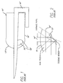
- Fig. 1 is a diagram which illustrates an illustrative application of a typical conventional gimbaled optical scanning system.
- the conventional scanning system 10° includes a gimbaled mirror 12' (not shown in Fig. 1) mounted within a dome 13' gimbaled in an aircraft platform 14'.
- the mirror 12' scans a beam 16' through a window 18'.
- Fig. 2 is a diagram which illustrates the field-of-regard of the typical conventional gimbaled optical scanning system of Fig. 1.
- the gimbaled mirror 12' receives the beam 16' through an entrance pupil 19' over a field of regard ⁇ .
- this use of steering mirrors requires an output window 18' many times the size of the system optical entrance pupil 16' to scan over a large field of regard ⁇ .
- this requires necessitates a large hole in the platform 14'.
- the dome 13' and associated optical assembly is bulky, typically requires considerable volume, and has a radar cross-section which tends to increases the observe-ability of the vehicle.
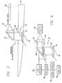
- Fig. 3 is a diagram showing an illustrative application of the optical beam steering system of the present invention.
- the beam steering system of the present invention 10 includes a device 20 which allows for electronic or electro-optical refractive steering of an input or output beam 16.
- the device is a broadband liquid crystal array.
- the beam 16 is refracted through an window 18 which is approximately equal, in dimension, to the entrance pupil 19 of the device 20.
- Fig. 4 is an isolated view of the optical beam steering system 10 of the present invention with associated control circuitry.
- the refracted beam 16 is corrected for dispersion by a dispersion arrangement 22 consisting of first and second counter-rotating wedges 24 and 26.
- the diameter of the wedges 24 and 26 is determined by the diameter of the beam 16.
- the wedge angles are determined by the color dispersion inherent in the material in the device 20 through which the beam propagates for the spectral components of the beam.
- the orientation of the wedges 24 and 26 is controlled by a servo-control system 28, which operates under command of a controller 30.
- the controller 30 may be implemented with a microprocessor, application specific integrated circuit, programmable digital logic circuit or other suitable circuit as will be appreciated by those of ordinary skill in the art.
- the controller may operate under command of a system controller 32, which would receive input from and provide output to a user via an interface 34.
- the controller 30 applies a voltage to the beam steering device 20, which determines the angle at which the beam is refractively steered thereby. Simultaneously, the controller supplies signals to the servo-controller 28 to make orientational adjustments to the wedges 24 and 26 required to correct for any color dispersion caused by the device 20.
- the dispersion corrected beam is directed to a mirror 36.
- the mirror 36 is a component of a compensating group 37 which includes a lens 38.
- the mirror 36 compensates for any small angular change in the beam 16 caused by the dispersion group 22.
- the flatness and spectral reflectance of the mirror are primary design considerations. The mirror should be as flat as practical for the application. The spectral reflectance will be set by the reflective coatings selected for the application.
- the lens serves to focus the beam 16 to a detector, camera or eyepiece 40.
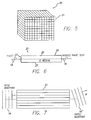
- Fig. 5 is a diagram of the liquid crystal array 20 utilized in the optical beam steering system 10 of the present invention. As shown in Fig. 5, the broadband beaming steering device 20 consists of a multi-channel array of channels 21.
- Fig. 6 is a sectional side view of a single liquid crystal channel of the array 20 of Fig. 5. As depicted in Fig. 6. each channel 21 of the array 20 is filled with a liquid crystal formulation 25 and acts as a waveguide. Application of a voltage across each channel 21 induces a change in refractive index of the liquid crystal material. This introduces a phase delay in the beam 16 as it propagates through each channel.
- Fig. 7 is a sectional side view of multiple liquid crystal channels of the array 20 of Fig. 5.
- a variation between the channel indices is created.
- the variation between channel indices applies a phase delay across an incident optical wavefront 16 to create an electro-optical wedge.
- the optical wedge can be manipulated electro-optically to scan the field-of-regard.
- the optical wedge of the liquid crystal component is manipulated by varying the applied voltage.
- the rotating wedges correct the residual dispersive color that is inherent in any optical medium. This dispersive color correction is a small angular component compared to the large angular scan generated by the liquid crystal component.
- Fig. 8a is a cross-sectional end view of multiple liquid crystal channels 21 of the array 20 of Fig. 5. As shown in Fig. 6 and 8a, each channel 21 is created by etching a cavity in a substrate 33 to create a cell 31.
- the cell size should be kept small to ensure single mode operation.
- the substrate 33 may he any suitable etchable material.
- the cells are 3 x 3 microns and are separated with I micron of substrate.
- a conductive material is flashed into the floor of the cell 31 to provide a ground 27.
- the cell 31 is filled with a liquid crystal material to provide a medium 25.
- a liquid crystal material to provide a medium 25.
- any material can be used as a medium so long as it refracts a beam of electro-magnetic energy in response to an applied voltage.
- a solution of 1% PTTP-15 dissolved in methylene chloride was chosen as the liquid crystal material for the medium 25.
- a voltage strip 29 of conductive material is applied as a cover for each cell. The voltage strip may be common in some embodiments. However, in most conservative embodiment, each cell has its own unique circuit and therefore, does not act as a common ground.
- a filter 23 is provided at the input aperture of each channel.
- An array (not shown) of conductors would be provided to allow for selective application of an applied voltage to an individual cell.
- Fig. 8b is a sectional side view of multiple liquid crystal channels of the array of Fig. 5 showing an arrangement by which leads are brought out of the cells.
- Each row has a layered insulated wiring routing as shown. The dimensions are exaggerated to illustrate the path.
- Each of the row outputs are staggered in space to avoid physical interference when organized along the column.
- Fig. 9 is a diagram which illustrates that the beam steering device of the present invention may be used for multiple laser frequency steering.
Landscapes
- Physics & Mathematics (AREA)
- Nonlinear Science (AREA)
- General Physics & Mathematics (AREA)
- Optics & Photonics (AREA)
- Liquid Crystal (AREA)
- Optical Modulation, Optical Deflection, Nonlinear Optics, Optical Demodulation, Optical Logic Elements (AREA)
Abstract
Description
Claims (10)
- A system (10) for steering a beam (16) of electromagnetic energy comprising:wherein the index of refraction of said beam steering device (20) varies in response to said applied voltage, and characterised in that:a beam steering device (20) for receiving an input wavefront of electromagnetic energy along a first axis and refracting said input wavefront as an output wavefront along a second axis at an angle with respect to said first axis in response to an applied voltage;contacts (27 and 29) for providing said voltage in response to a control signal; anda controller (30) for providing said control signal,the beam steering device comprises a two-dimensional multi-channel array of liquid crystal channels (21), wherein the channels have a length which is parallel to the first axis.
- The system of claim 1, wherein each of the channels is a single mode optical waveguide.
- The system of claim 1, further including an arrangement (22) for restoring color balance to said output wavefront, wherein said arrangement (22) for restoring color balance to said output wavefront includes first and second counter-rotating optical wedges (24, 26).
- The system of claim 3, further including a mirror (36) for compensating a wavefront output by said first and second counter-rotating optical wedges.
- The system of claim 4 further including an imaging lens (38).
- The system of claim 1, wherein the beam steering device comprises a substrate (33), and a channel (21) is created by etching a cavity in the substrate (33).
- The system of claim 1, in which each channel comprises a conductive material flashed into one wall of the channel to provide a ground (27), and a voltage strip (29) of conductive material applied to an opposite wall of the channel.
- The system of claim 1, in which the voltage strip (29) is common to a plurality of channels (21).
- The system of claim 1, further comprising a filter (23) provided at an input aperture of each channel (21).
- The system of claim 1, wherein the array has rows and columns, each row of the array having a layered insulated wiring routing output (35), and each of the row outputs being staggered in space to avoid physical interference when organised along columns of the array.
Applications Claiming Priority (3)
| Application Number | Priority Date | Filing Date | Title |
|---|---|---|---|
| US516812 | 2000-03-01 | ||
| US09/516,812 US6765644B1 (en) | 2000-03-01 | 2000-03-01 | Broadband optical beam steering system and method |
| EP01913208A EP1208405B1 (en) | 2000-03-01 | 2001-03-01 | Broadband optical beam steering system and method |
Related Parent Applications (2)
| Application Number | Title | Priority Date | Filing Date |
|---|---|---|---|
| EP01913208.3 Division | 2001-03-01 | ||
| EP01913208A Division EP1208405B1 (en) | 2000-03-01 | 2001-03-01 | Broadband optical beam steering system and method |
Publications (3)
| Publication Number | Publication Date |
|---|---|
| EP1455220A2 true EP1455220A2 (en) | 2004-09-08 |
| EP1455220A3 EP1455220A3 (en) | 2005-03-30 |
| EP1455220B1 EP1455220B1 (en) | 2010-05-26 |
Family
ID=24057190
Family Applications (2)
| Application Number | Title | Priority Date | Filing Date |
|---|---|---|---|
| EP01913208A Expired - Lifetime EP1208405B1 (en) | 2000-03-01 | 2001-03-01 | Broadband optical beam steering system and method |
| EP04076375A Expired - Lifetime EP1455220B1 (en) | 2000-03-01 | 2001-03-01 | Broadband optical beam steering system and method |
Family Applications Before (1)
| Application Number | Title | Priority Date | Filing Date |
|---|---|---|---|
| EP01913208A Expired - Lifetime EP1208405B1 (en) | 2000-03-01 | 2001-03-01 | Broadband optical beam steering system and method |
Country Status (5)
| Country | Link |
|---|---|
| US (2) | US6765644B1 (en) |
| EP (2) | EP1208405B1 (en) |
| DE (2) | DE60105944T2 (en) |
| IL (1) | IL146261A (en) |
| WO (1) | WO2001065312A2 (en) |
Families Citing this family (9)
| Publication number | Priority date | Publication date | Assignee | Title |
|---|---|---|---|---|
| WO2007004280A1 (en) * | 2005-07-01 | 2007-01-11 | Fujitsu Limited | Liquid crystal composition, liquid crystal display element using the same, and electronic paper comprising said liquid crystal display element |
| US7385768B2 (en) * | 2005-11-22 | 2008-06-10 | D + S Consulting, Inc. | System, method and device for rapid, high precision, large angle beam steering |
| US7999841B1 (en) | 2006-08-18 | 2011-08-16 | Lockheed Martin Corporation | Image expansion system to create larger size or larger resolution images |
| US8982210B2 (en) | 2010-06-30 | 2015-03-17 | Lockheed Martin Corporation | Vehicle having scanning imager with fixed camera and multiple achromatic prism pairs |
| US8575527B2 (en) | 2010-11-10 | 2013-11-05 | Lockheed Martin Corporation | Vehicle having side portholes and an array of fixed EO imaging sub-systems utilizing the portholes |
| US9476981B2 (en) | 2013-01-08 | 2016-10-25 | Massachusetts Institute Of Technology | Optical phased arrays |
| EP3388892A1 (en) | 2013-01-08 | 2018-10-17 | Massachusetts Institute Of Technology | Optical phased arrays |
| US10281564B2 (en) | 2016-06-29 | 2019-05-07 | Aptiv Technologies Limited | Refractive beam steering device useful for automated vehicle LIDAR |
| US11143860B1 (en) | 2019-04-29 | 2021-10-12 | United States Of America As Represented By The Secretary Of The Air Force | Photonic crystal-based optical steering |
Family Cites Families (25)
| Publication number | Priority date | Publication date | Assignee | Title |
|---|---|---|---|---|
| US3626511A (en) * | 1970-07-20 | 1971-12-07 | Rca Corp | Digital light deflector using electro-optic grating |
| US3650602A (en) * | 1970-08-19 | 1972-03-21 | Honeywell Inc | Parallel array light beam deflector with variable phase plate |
| US3658424A (en) * | 1971-01-14 | 1972-04-25 | Spectra Metrics Inc | Method of focusing the horizontal and vertical components from an echelle grating |
| US3900263A (en) * | 1974-01-04 | 1975-08-19 | Jr Joseph F Hall | Method for minimizing deviation in optical dispersion systems |
| US4131021A (en) * | 1976-03-04 | 1978-12-26 | Rca Corporation | High resolution pulse-echo ultrasonic-imaging display system |
| FR2541784B1 (en) * | 1983-02-25 | 1986-05-16 | Thomson Csf | DEVICE FOR STATIC DEFLECTION OF AN INFRARED BEAM |
| US4971413A (en) * | 1987-05-13 | 1990-11-20 | Nikon Corporation | Laser beam depicting apparatus |
| US5151814A (en) * | 1987-08-19 | 1992-09-29 | Hughes Aircraft Company | Phased array for optical beam control |
| IT1223661B (en) * | 1988-07-04 | 1990-09-29 | Cselt Centro Studi Lab Telecom | ELECTRO OPTICAL DEFLECTOR |
| US4973112A (en) * | 1988-12-01 | 1990-11-27 | Holotek Ltd. | Hologon deflection system having dispersive optical elements for scan line bow correction, wavelength shift correction and scanning spot ellipticity correction |
| US4972112A (en) * | 1989-06-12 | 1990-11-20 | Kim Dae W | Brushless DC motor |
| US4963900A (en) * | 1989-08-01 | 1990-10-16 | International Business Machines Corporation | Multiple laser beam scanning optics |
| US5253033A (en) * | 1990-12-03 | 1993-10-12 | Raytheon Company | Laser radar system with phased-array beam steerer |
| US5126869A (en) | 1990-12-03 | 1992-06-30 | Raytheon Company | Two-dimensional, phased-array optical beam steerer |
| US5093747A (en) * | 1991-02-28 | 1992-03-03 | Raytheon Company | Method for providing beam steering in a subaperture-addressed optical beam steerer |
| US5212583A (en) * | 1992-01-08 | 1993-05-18 | Hughes Aircraft Company | Adaptive optics using the electrooptic effect |
| US5363126A (en) * | 1992-09-25 | 1994-11-08 | Xerox Corporation | Device and apparatus for high speed tracking in a raster output scanner |
| CA2107194C (en) * | 1992-12-11 | 1999-08-31 | Ellis D. Harris | Binary diffractive optical element scanner |
| DE69325783T2 (en) * | 1992-12-11 | 1999-11-18 | Raytheon Co., El Segundo | Achromatic and apochromatic prism element made of prism and grids |
| JPH0764123A (en) * | 1993-08-20 | 1995-03-10 | Internatl Business Mach Corp <Ibm> | Distributed-refractive-index type light deflector and method of optical deflection |
| IL111392A (en) * | 1994-10-25 | 2000-02-17 | Elop Electrooptics Ind Ltd | Linear beam steering |
| US5615029A (en) * | 1995-03-08 | 1997-03-25 | Electronics & Space Corp. | Electro-optic wedge structure for beam steering and method of manufacture |
| US6169594B1 (en) * | 1998-08-24 | 2001-01-02 | Physical Optics Corporation | Beam deflector and scanner |
| US6344937B1 (en) * | 1999-03-03 | 2002-02-05 | Raytheon Company | Beam steering optical arrangement using Risley prisms with surface contours for aberration correction |
| US6317190B1 (en) * | 1999-06-14 | 2001-11-13 | International Business Machines Corporation | Variable focal length liquid crystal lens assembly and method of manufacture |
-
2000
- 2000-03-01 US US09/516,812 patent/US6765644B1/en not_active Expired - Lifetime
-
2001
- 2001-03-01 IL IL14626101A patent/IL146261A/en active IP Right Grant
- 2001-03-01 DE DE60105944T patent/DE60105944T2/en not_active Expired - Lifetime
- 2001-03-01 WO PCT/US2001/006594 patent/WO2001065312A2/en not_active Ceased
- 2001-03-01 DE DE60142258T patent/DE60142258D1/en not_active Expired - Lifetime
- 2001-03-01 EP EP01913208A patent/EP1208405B1/en not_active Expired - Lifetime
- 2001-03-01 EP EP04076375A patent/EP1455220B1/en not_active Expired - Lifetime
-
2004
- 2004-05-03 US US10/838,823 patent/US6947117B2/en not_active Expired - Lifetime
Also Published As
| Publication number | Publication date |
|---|---|
| EP1455220A3 (en) | 2005-03-30 |
| US20040240766A1 (en) | 2004-12-02 |
| WO2001065312A2 (en) | 2001-09-07 |
| DE60105944D1 (en) | 2004-11-04 |
| DE60142258D1 (en) | 2010-07-08 |
| EP1208405A2 (en) | 2002-05-29 |
| US6947117B2 (en) | 2005-09-20 |
| IL146261A (en) | 2005-07-25 |
| EP1455220B1 (en) | 2010-05-26 |
| US6765644B1 (en) | 2004-07-20 |
| DE60105944T2 (en) | 2006-03-09 |
| EP1208405B1 (en) | 2004-09-29 |
| WO2001065312A3 (en) | 2002-03-14 |
| IL146261A0 (en) | 2002-07-25 |
Similar Documents
| Publication | Publication Date | Title |
|---|---|---|
| Tholl | Novel laser beam steering techniques | |
| EP0377498B1 (en) | Deflector for an optical beam including refractive means | |
| US20210356838A1 (en) | Non-moving optical beam steering using non-pixelated liquid crystal optical phased arrays | |
| KR101603778B1 (en) | Optical image shutter | |
| US6751009B2 (en) | Acousto-micro-optic deflector | |
| US6891676B2 (en) | Tunable spectral filter | |
| US6388815B1 (en) | Device and method for producing optically-controlled incremental time delays | |
| AU4240893A (en) | Pixel intensity modulator | |
| EP1210641A1 (en) | Device for producing optically-controlled incremental time delays | |
| EP1455220B1 (en) | Broadband optical beam steering system and method | |
| WO1997031442A1 (en) | Multiple reflection multiplexer and demultiplexer | |
| US5054873A (en) | High density integrated optical multiplexer/demultiplexer | |
| JP2772777B2 (en) | Sun tracking device | |
| WO2004023197A1 (en) | Method and device for variable optical attenuator | |
| US20230134418A1 (en) | Pointing units and methods of operating pointing units | |
| KR20190127429A (en) | Dual camera module including liquid lens | |
| US12348266B2 (en) | Pointing units and methods of operating pointing units | |
| CN114740617A (en) | Large-view-field high-resolution all-solid-state optical scanning system | |
| CN120161621B (en) | Large-view-field compact bifocal HUD system and imaging method | |
| US20260043678A1 (en) | Beam tracking and fiber coupling using dual focus diffractive optical element | |
| US4098548A (en) | Light optic data handling system | |
| US6707961B1 (en) | Optical cross-connect switch with decreased polarization-dependent loss | |
| Paek et al. | 2D multiple beam steering with acoustically steered and rotated (ASTRO) true-time delay generator | |
| Howell et al. | Patent Reviews: 4,659,185; 4,688,881; 4,690,500; 4,693,547; 4,693,549; 4,693,569; 4,699,452; 4,699,464; 4,699,465; 4,701,005; 4,701,006; 4,701,009; 4,701,031; 4,701,033; 4,701,034; 4,702,245; 4,702,547; 4,702,548; 4,703,993; 4,703,994; 4,703,996; 4,705,345; 4,705,351; 4,705,354; 4,705,356; 4,705,362; 4,705,363; 4,705,364; 4,707,054; 4,707,055; 4,707,063; 4,707,077; 4,707,081; 4,707,082; 4,707,084; 4,707,085; 4,707,098; 4,707,611; 4,711,533; 4,711,534; 4,711,535; 4,711,536 |
Legal Events
| Date | Code | Title | Description |
|---|---|---|---|
| PUAI | Public reference made under article 153(3) epc to a published international application that has entered the european phase |
Free format text: ORIGINAL CODE: 0009012 |
|
| AC | Divisional application: reference to earlier application |
Ref document number: 1208405 Country of ref document: EP Kind code of ref document: P |
|
| AK | Designated contracting states |
Kind code of ref document: A2 Designated state(s): DE FR GB |
|
| PUAL | Search report despatched |
Free format text: ORIGINAL CODE: 0009013 |
|
| AK | Designated contracting states |
Kind code of ref document: A3 Designated state(s): DE FR GB |
|
| RIC1 | Information provided on ipc code assigned before grant |
Ipc: 7G 02F 1/13 B Ipc: 7G 02F 1/295 A Ipc: 7G 02F 1/1335 B |
|
| 17P | Request for examination filed |
Effective date: 20050909 |
|
| AKX | Designation fees paid |
Designated state(s): DE FR GB |
|
| 17Q | First examination report despatched |
Effective date: 20090319 |
|
| GRAP | Despatch of communication of intention to grant a patent |
Free format text: ORIGINAL CODE: EPIDOSNIGR1 |
|
| GRAS | Grant fee paid |
Free format text: ORIGINAL CODE: EPIDOSNIGR3 |
|
| GRAA | (expected) grant |
Free format text: ORIGINAL CODE: 0009210 |
|
| AC | Divisional application: reference to earlier application |
Ref document number: 1208405 Country of ref document: EP Kind code of ref document: P |
|
| AK | Designated contracting states |
Kind code of ref document: B1 Designated state(s): DE FR GB |
|
| REG | Reference to a national code |
Ref country code: GB Ref legal event code: FG4D |
|
| REF | Corresponds to: |
Ref document number: 60142258 Country of ref document: DE Date of ref document: 20100708 Kind code of ref document: P |
|
| PLBE | No opposition filed within time limit |
Free format text: ORIGINAL CODE: 0009261 |
|
| STAA | Information on the status of an ep patent application or granted ep patent |
Free format text: STATUS: NO OPPOSITION FILED WITHIN TIME LIMIT |
|
| 26N | No opposition filed |
Effective date: 20110301 |
|
| REG | Reference to a national code |
Ref country code: DE Ref legal event code: R097 Ref document number: 60142258 Country of ref document: DE Effective date: 20110228 |
|
| REG | Reference to a national code |
Ref country code: FR Ref legal event code: PLFP Year of fee payment: 16 |
|
| REG | Reference to a national code |
Ref country code: FR Ref legal event code: PLFP Year of fee payment: 17 |
|
| REG | Reference to a national code |
Ref country code: FR Ref legal event code: PLFP Year of fee payment: 18 |
|
| PGFP | Annual fee paid to national office [announced via postgrant information from national office to epo] |
Ref country code: DE Payment date: 20180214 Year of fee payment: 18 |
|
| REG | Reference to a national code |
Ref country code: DE Ref legal event code: R119 Ref document number: 60142258 Country of ref document: DE |
|
| PG25 | Lapsed in a contracting state [announced via postgrant information from national office to epo] |
Ref country code: DE Free format text: LAPSE BECAUSE OF NON-PAYMENT OF DUE FEES Effective date: 20191001 |
|
| PGFP | Annual fee paid to national office [announced via postgrant information from national office to epo] |
Ref country code: GB Payment date: 20200219 Year of fee payment: 20 |
|
| PGFP | Annual fee paid to national office [announced via postgrant information from national office to epo] |
Ref country code: FR Payment date: 20200113 Year of fee payment: 20 |
|
| REG | Reference to a national code |
Ref country code: GB Ref legal event code: PE20 Expiry date: 20210228 |
|
| PG25 | Lapsed in a contracting state [announced via postgrant information from national office to epo] |
Ref country code: GB Free format text: LAPSE BECAUSE OF EXPIRATION OF PROTECTION Effective date: 20210228 |