EP1455211A2 - Lens mount with an integrated lens - Google Patents
Lens mount with an integrated lens Download PDFInfo
- Publication number
- EP1455211A2 EP1455211A2 EP04250906A EP04250906A EP1455211A2 EP 1455211 A2 EP1455211 A2 EP 1455211A2 EP 04250906 A EP04250906 A EP 04250906A EP 04250906 A EP04250906 A EP 04250906A EP 1455211 A2 EP1455211 A2 EP 1455211A2
- Authority
- EP
- European Patent Office
- Prior art keywords
- lens
- holder
- optical
- openings
- assembly
- Prior art date
- Legal status (The legal status is an assumption and is not a legal conclusion. Google has not performed a legal analysis and makes no representation as to the accuracy of the status listed.)
- Granted
Links
Images


Classifications
-
- G—PHYSICS
- G02—OPTICS
- G02B—OPTICAL ELEMENTS, SYSTEMS OR APPARATUS
- G02B7/00—Mountings, adjusting means, or light-tight connections, for optical elements
- G02B7/02—Mountings, adjusting means, or light-tight connections, for optical elements for lenses
- G02B7/022—Mountings, adjusting means, or light-tight connections, for optical elements for lenses lens and mount having complementary engagement means, e.g. screw/thread
-
- C—CHEMISTRY; METALLURGY
- C03—GLASS; MINERAL OR SLAG WOOL
- C03B—MANUFACTURE, SHAPING, OR SUPPLEMENTARY PROCESSES
- C03B11/00—Pressing molten glass or performed glass reheated to equivalent low viscosity without blowing
- C03B11/06—Construction of plunger or mould
- C03B11/08—Construction of plunger or mould for making solid articles, e.g. lenses
-
- C—CHEMISTRY; METALLURGY
- C03—GLASS; MINERAL OR SLAG WOOL
- C03B—MANUFACTURE, SHAPING, OR SUPPLEMENTARY PROCESSES
- C03B2215/00—Press-moulding glass
- C03B2215/40—Product characteristics
- C03B2215/46—Lenses, e.g. bi-convex
-
- C—CHEMISTRY; METALLURGY
- C03—GLASS; MINERAL OR SLAG WOOL
- C03B—MANUFACTURE, SHAPING, OR SUPPLEMENTARY PROCESSES
- C03B2215/00—Press-moulding glass
- C03B2215/72—Barrel presses or equivalent, e.g. of the ring mould type
- C03B2215/73—Barrel presses or equivalent, e.g. of the ring mould type with means to allow glass overflow in a direction perpendicular to the press axis
-
- C—CHEMISTRY; METALLURGY
- C03—GLASS; MINERAL OR SLAG WOOL
- C03B—MANUFACTURE, SHAPING, OR SUPPLEMENTARY PROCESSES
- C03B2215/00—Press-moulding glass
- C03B2215/79—Uniting product and product holder during pressing, e.g. lens and lens holder
Definitions
- the present invention relates to holder/optical-element assemblies in which an optical element is integrated with a holder, and particularly, to a holder/optical-element assembly formed by press-molding an optical-element material.
- Optical elements such as lenses used in digital cameras and in pickup heads of CD players, require high precision when installing.
- this high-precision installation is generally achieved by forming a holder/optical-element assembly, in which the optical element is held by the holder, and then adjusting the position of the holder during the installation.
- the optical element is formed by setting an optical-element material within a cylindrical holder, heating the material until it softens, and then press-molding the softened material using a mold. This forms the optical element and also allows the element to be press-fitted to the holder so as to achieve integration of the element and the holder.
- the thickness of the optical element may vary. This not only deteriorates the optical quality but also requires adjustment and fixing to an appropriate optical position, thus causing problems in terms of performance and positioning.
- An object of the present invention is to provide a high-precision holder/optical-element assembly that is capable of compensating for volume errors of an optical-element material.
- the present invention provides a holder/optical-element assembly which includes a cylindrical holder and an optical element disposed within the holder.
- the holder has an inner periphery surface in which at least one opening is provided, and the optical element is provided with at least one protrusion extending outward from the periphery of the optical element.
- the protrusion of the optical element is supported by the opening of the holder.
- the protrusion of the optical element may consist of an additional volume of material for the optical element.
- the holder may be provided with at least one engagement groove along the inner periphery surface of the holder.
- the engagement groove acts as the opening.
- the holder may be provided with multiple micro-pores over the inner periphery surface of the holder.
- the micro-pores act as the openings.
- the holder may be provided with multiple micro-pores over a part of the inner periphery surface of the holder.
- the micro-pores act as the openings.
- the openings may absorb the volume error of the optical-element material during press-molding of the optical element to achieve higher precision for the optical-element formation, thereby providing a holder/optical element assembly having a high-precision optical element without the need for improving the precision of the holder.
- FIG. 1 is a cross-sectional view of a holder/optical-element assembly 1 according to the first embodiment of the present invention.
- Figs. 2A and 2B are cross-sectional views of the assembly 1 in its manufacturing process.
- the assembly 1 is used in, for example, a digital camera or a pickup head of a CD player.
- the assembly 1 includes a cylindrical lens holder 10 and a spherical lens 20 that is disposed within the lens holder 10.
- the lens holder 10 holds the lens 20 and is provided for the positioning of the lens 20 in an optical apparatus.
- the lens holder 10 is formed by, for example, cutting or casting a material such as aluminum and stainless steel.
- the lens holder 10 is provided with openings 12, namely, engagement grooves 12a, along the inner periphery surface 11 of the lens holder 10.
- the lens 20 is a biconvex spherical lens and, as shown in Fig. 2A, is formed by press-molding a lens material 20a. During press-molding, the applied pressure causes the lens material 20a to be press-fitted to the lens holder 10, whereby the lens 20 is integrated with the lens holder 10. Extending outward partially from the periphery 21 of the lens 20 are protrusions 21a, which engage with the openings 12.
- the lens material 20a is composed of an optical glass, such as SFS01 which is a lead-oxide glass material. With respect to the required volume of the lens material 20a for forming the lens 20, the material 20a is deliberately provided with an additional volume. This additional volume compensates for a volume error existing in the lens material 20a, and therefore, the required volume of the lens material 20a for forming the lens 20 is ensured.
- SFS01 a lead-oxide glass material
- the pressure applied during the press-molding of the lens 20 causes the additional volume of the lens material 20a to flow into the openings 12, namely, the engagement grooves 12a, thereby forming the protrusions 21a.
- the additional volume of the lens material 20a which is a volume not originally required for forming the lens 20, is absorbed by the openings 12. This means that the volume error included in the additional volume is also absorbed by the openings 12, thereby achieving the formation of a high-precision lens 20 with a desired shape.
- the openings 12 apply a flow resistance against the lens material 20a. If the widths of the engagement grooves 12a forming the openings 12 are large, the flow resistance of the openings 12 is low overall. On the other hand, if the widths are small, the flow resistance is high.
- the number and the width of the grooves 12a may be modified depending on, for example, the viscosity of the lens material 20a. In other words, by coordinating the number and the width of the grooves 12a, the flow resistance of the openings 12 may be adjusted with respect to the lens material 20a.
- the volume of the openings 12 must be larger than the additional volume of the lens material 20a.
- a high flow resistance may excessively interfere with the flow of the lens material 20a into the openings 12 and may cause the additional volume itself to cause a formation error of the lens 20.
- a low flow resistance causes the lens material 20a to flow into the openings 12 too easily when the molding pressure is applied, thus causing the lens material 20a to fill the openings 12.
- the spatial volume of the openings 12 is made larger than the additional volume of the lens material 20a, if the openings 12 are filled with the lens material 20a, the original required volume of the lens material 20a for forming the lens 20 would also leak into the openings 12. This would result in a formation error of the lens 20.
- the flow resistance of the openings 12 needs to be adjusted to an extent such that the whole additional volume of the lens material 20a may flow into the openings 12 by the molding pressure while the original required volume is prevented from entering the openings 12.
- the flow resistance of the openings 12 needs to be adjusted with respect to the viscosity of the lens material 20a or different molding pressures. In other words, if the viscosity of the lens material 20a is near the glass transition-point and the fluidity of the material 20a is low, the flow resistance of the openings 12 needs to be set lower. On the other hand, if the viscosity is near the softening point and the fluidity is high, the flow resistance of the openings 12 needs to be set higher.
- the flow resistance of the openings 12 is adjusted such that if the molding pressure is low, the resistance is made smaller, and vice versa. Based on these conditions, by selecting an appropriate shape for the openings 12 with a flow resistance that brings out the desired functionality, a flexible adjustment can be made with respect to, for example, a material change of the lens material 20a. Alternatively, the molding pressure or the viscosity of the lens material 20a may be adjusted if possible.
- FIGs. 2A and 2B each illustrate a manufacturing device 80 for the assembly 1.
- the manufacturing device 80 includes an upper mold A provided with an inner upper-mold component 81 and an outer upper-mold component 82. Below these components 81 and 82 are an inner lower-mold component 83 and an outer lower-mold component 84, respectively, which form a lower mold B. Furthermore, the upper and lower molds A and B are enclosed by an enclosing mold C.
- the inner upper-mold component 81 and the inner lower-mold component 83 substantially have a column-like structure.
- the lower end of the component 81 and the upper end of the component 83, respectively, are provided with transferring surfaces 81a and 83a for molding the surfaces of the spherical lens.
- the outer upper-mold component 82 and the outer lower-mold component 84 are tubular and enclose the respective components 81 and 83.
- the wall thickness of the components 82 and 84 is substantially equivalent to that of the lens holder 10, and the inner circumference of the enclosing mold C is substantially equivalent to the outer circumference of the lens holder 10.
- the components 81 and 82 are slidable independently in the vertical direction.
- the lens holder 10 pre-formed to predetermined dimensions by, for example, cutting is first placed on the component 84, and the lens material 20a is then disposed within the lens holder 10.
- a heater facing the periphery of the lens holder 10 is provided for heating the holder 10 so as to heat the lens material 20a to a temperature exceeding its softening point. Furthermore, the lens material 20a may be pre-heated before being disposed in the lens holder 10.
- the material 20a is press-molded.
- the outer upper-mold component 82 is lowered to the lens holder 10 disposed on the outer lower-mold component 84 so that the lens holder 10 is secured between the component 82 and the component 84.
- the inner upper-mold component 81 is then lowered to the softened lens material 20a disposed on the inner lower-mold component 83 so that transferring surfaces 81a and 83a of the respective components 81 and 83 apply pressure against the lens material 20a. Consequently, the lens 20, that is, a biconvex spherical lens, is formed.
- This press-molding process is performed within the range where the viscosity of the lens material 20a is between the glass transition-point and the softening point.
- the molding pressure forces the additional volume of the material 20a to flow into the grooves 12a provided along the inner periphery surface 11 of the lens holder 10, thereby forming the protrusions 21a.
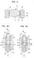
- FIG. 3 is a cross-sectional view of a holder/optical-element assembly 2 according to the second embodiment.
- Figs. 4A and 4B are cross-sectional views of the assembly 2 in its manufacturing process.
- the assembly 2 is used in, for example, a digital camera or a pickup head of a CD player, like the assembly 1 of the first embodiment.
- the assembly 2 includes a cylindrical lens holder 30, and a spherical lens 40 that is disposed within the lens holder 30.
- the lens holder 30 is composed of, for example, aluminum or stainless steel and is provided with openings 32, namely, multiple pores 32a, throughout the entire structure of the lens holder 30.
- the lens holder 30 with its openings 32, i.e. pores 32a, is formed by, for example, powder-sintering or porous-metal forming.
- the lens 40 which is formed of glass, is disposed within the lens holder 30.
- the lens 40 is a biconvex spherical lens and, as shown in Fig. 4A, is formed by press-molding a lens material 40a. During press-molding, the applied pressure causes the lens material 40a to be press-fitted to the lens holder 30, whereby the lens 40 is integrated with the lens holder 30. Extending outward substantially from the entire surface of the periphery 41 of the lens 40 are protrusions 41a, which engage with the openings 32.
- the material 40a is deliberately provided with an additional volume, as in the first embodiment.
- the pressure applied during the press-molding of the lens 40 causes the additional volume of the lens material 40a to flow into the openings 32, namely, the pores 32a, thereby forming the protrusions 41a.
- the additional volume of the lens material 40a which is a volume not originally required for forming the lens 40, is absorbed by the openings 32 along with the volume error to achieve the formation of a high-precision lens 40 with a desired shape.
- the openings 32 apply a flow resistance against the lens material 40a, as in the first embodiment. If the diameters of the pores 32a are large, the flow resistance is low, whereas if the diameters are small, the flow resistance is high.
- the flow resistance of the openings 32 needs to be adjusted to an extent such that the whole additional volume of the lens material of the lens material 40a may flow into the openings 32 by the molding pressure while the original required volume is prevented from entering the openings 32.
- the adjustment of the flow resistance of the openings 32 must be made with respect to the viscosity of the lens material 40a or different molding pressures.
- the spatial volume of the openings 32 must be larger than the additional volume of the lens material 40a.
- the flow resistance of the openings 32 against the lens material 40a may be adjusted by changing the porosity, that is, the ratio of the pores 32a to the overall volume of the lens holder 30.
- the porosity is preferably in a range from 30% to 60% by powder-sintering, and 50% to 95% by porous-metal forming.
- the pores 32a have a size ranging from a few microns to 100 ⁇ m and must be continuous.
- the manufacturing device 80 for the assembly 2 is the same as that of the first embodiment, and the description of the structure will therefore be omitted.
- the lens holder 30 pre-formed to predetermined dimensions by, for example, powder-sintering or porous-metal forming is first placed on the outer lower-mold component 84, and the lens material 40a is then disposed within the lens holder 30.
- the material 40a is press-molded.
- the molding pressure applied to the lens material 40a forces the additional volume of the material 40a to flow into the openings 32 over the inner periphery surface 31 of the lens holder 30, thereby forming the protrusions 41a.
- FIG. 5 is a cross-sectional view of a holder/optical-element assembly 3 according to the third embodiment.
- Figs. 6A and 6B are cross-sectional views of the assembly 3 in its manufacturing process.
- the assembly 3 is used in, for example, a digital camera or a pickup head of a CD player, like the assemblies 1 and 2 of the first and second embodiments.
- the assembly 3 includes a cylindrical lens holder 50, and a spherical lens 60 that is disposed within the lens holder 50.
- the lens holder 50 includes an inner holder part 52 and an outer holder part 53.
- the part 52 is cylindrical and is disposed within the interior side of the lens holder 50.
- the part 52 occupies a part of the inner periphery surface 51 of the lens holder 50.
- the part 52 is composed of, for example, aluminum or stainless steel and is provided with openings 54, namely, multiple pores 54a, throughout the entire structure of the part 52.
- the part 52 with its openings 54, i.e. pores 54a is formed by, for example, powder-sintering or porous-metal forming.
- the requirements for the openings 54 are similar to those in the second embodiment.
- the outer holder part 53 is formed by, for example, cutting or casting a material such as aluminum and stainless steel.
- the part 53 encloses the outer periphery of the part 52 and at least one of the surfaces of the part 52 that contacts the part 53.
- the part 53 ensures airtight installation of the assembly 3 in an optical apparatus. This ensured airtightness of the assembly 3 prevents, for example, internal corrosion of an optical apparatus caused by moisture.
- the part 52 is fixed to the part 53 by, for example, press-fitting or welding for the integration of the two parts 52 and 53.
- the lens 60 which is formed of glass, is disposed within the lens holder 50.
- the lens 60 is a biconvex spherical lens and, as shown in Fig. 6A, is formed by press-molding a lens material 60a. During press-molding, the applied pressure causes the lens material 60a to be press-fitted to the lens holder 50, whereby the lens 60 is integrated with the lens holder 50. Extending outward partially from the periphery 61 of the lens 60 are protrusions 61a, which engage with the openings 54.
- the material 60a is deliberately provided with an additional volume, as in the first and second embodiments.
- the pressure applied during the press-molding of the lens 60 causes the additional volume of the lens material 60a to flow into the openings 54, namely, the pores 54a, thereby forming the protrusions 61a.
- the additional volume of the lens material 60a which is a volume not originally required for forming the lens 60, is absorbed by the openings 54 along with the volume error to achieve the formation of a high-precision lens 60 with a desired shape.
- the manufacturing device 80 for the assembly 3 is the same as those of the first and second embodiments, and the description of the structure will therefore be omitted.
- the lens holder 50 which is pre-formed to predetermined dimensions and includes the parts 52 and 53, is first placed on the outer lower-mold component 84.
- the lens material 60a is then disposed within the lens holder 50.
- the material 60a is press-molded.
- the molding pressure applied to the lens material 60a forces the additional volume of the material 60a to flow into the openings 54 of the inner holder part 52 of the lens holder 50, thereby forming the protrusions 61a.
- the present invention is not limited to this lens type.
- the present invention may also be applied to a lens with a different shape, such as a concave lens.
- the present invention is not limited to lenses and may apply to other optical elements, such as a diffraction grating integrated with a holder.
Landscapes
- Engineering & Computer Science (AREA)
- Chemical & Material Sciences (AREA)
- Physics & Mathematics (AREA)
- Manufacturing & Machinery (AREA)
- Materials Engineering (AREA)
- Organic Chemistry (AREA)
- General Physics & Mathematics (AREA)
- Optics & Photonics (AREA)
- Lens Barrels (AREA)
- Optical Head (AREA)
Abstract
Description
Claims (5)
- A holder/optical-element assembly comprising an optical element disposed within a cylindrical holder,
wherein the holder has an inner periphery surface in which at least one opening is provided, and the optical element has at least one protrusion extending outward from the periphery of the optical element, the protrusion being supported by the opening. - The holder/optical-element assembly according to Claim 1, wherein the protrusion of the optical element consists of an additional volume of material for the optical element.
- The holder/optical-element assembly according to Claim 2, wherein the holder comprises at least one engagement groove along the inner periphery surface of the holder, the engagement groove acting as the opening.
- The holder/optical-element assembly according to Claim 2, wherein the holder comprises multiple micro-pores over the entire inner periphery surface of the holder, the micro-pores acting as the openings.
- The holder/optical-element assembly according to Claim 2, wherein the holder comprises multiple micro-pores over a part of the inner periphery surface of the holder, the micro-pores acting as the openings.
Applications Claiming Priority (2)
| Application Number | Priority Date | Filing Date | Title |
|---|---|---|---|
| JP2003060947 | 2003-03-07 | ||
| JP2003060947A JP2004271782A (en) | 2003-03-07 | 2003-03-07 | Optical device with holder |
Publications (3)
| Publication Number | Publication Date |
|---|---|
| EP1455211A2 true EP1455211A2 (en) | 2004-09-08 |
| EP1455211A3 EP1455211A3 (en) | 2004-09-15 |
| EP1455211B1 EP1455211B1 (en) | 2006-09-27 |
Family
ID=32767879
Family Applications (1)
| Application Number | Title | Priority Date | Filing Date |
|---|---|---|---|
| EP04250906A Expired - Lifetime EP1455211B1 (en) | 2003-03-07 | 2004-02-20 | Lens mount with an integrated lens |
Country Status (5)
| Country | Link |
|---|---|
| US (1) | US7180688B2 (en) |
| EP (1) | EP1455211B1 (en) |
| JP (1) | JP2004271782A (en) |
| CN (1) | CN1288469C (en) |
| DE (1) | DE602004002500T2 (en) |
Families Citing this family (19)
| Publication number | Priority date | Publication date | Assignee | Title |
|---|---|---|---|---|
| JP2005208330A (en) * | 2004-01-22 | 2005-08-04 | Nippon Sheet Glass Co Ltd | Formed optical component with holder and manufacturing method therefor |
| WO2006000352A1 (en) | 2004-06-29 | 2006-01-05 | Carl Zeiss Smt Ag | Positioning unit and alignment device for an optical element |
| JP4481750B2 (en) * | 2004-07-08 | 2010-06-16 | 日本板硝子株式会社 | Method for manufacturing optical component with holder |
| CN101031828A (en) * | 2004-07-20 | 2007-09-05 | 新加坡科技研究局 | Variable focus microlens |
| US7372647B2 (en) * | 2004-12-29 | 2008-05-13 | Finisar Corporation | Lens mount assembly for optical components |
| JP4773756B2 (en) * | 2005-07-07 | 2011-09-14 | 富士フイルム株式会社 | Mirror frame, lens frame manufacturing method, lens frame molding die, and lens positioning method |
| WO2009005317A2 (en) * | 2007-07-03 | 2009-01-08 | Optomecha Co., Ltd. | Lens unit composed of different materials and camera module and method for manufacturing the same |
| JP2009037055A (en) * | 2007-08-02 | 2009-02-19 | Hitachi Maxell Ltd | Optical element with lens barrel and mold for optical element molding |
| JP2009086075A (en) * | 2007-09-28 | 2009-04-23 | Alps Electric Co Ltd | Lens with lens barrel |
| KR100973005B1 (en) * | 2008-08-04 | 2010-07-30 | 삼성전기주식회사 | Lens module |
| US8916090B2 (en) * | 2011-07-07 | 2014-12-23 | Karl Storz Imaging, Inc. | Endoscopic camera component manufacturing method |
| CN102914846B (en) * | 2011-08-05 | 2014-12-10 | 富泰华工业(深圳)有限公司 | Electronic device and adopted lens module |
| WO2013125367A1 (en) * | 2012-02-22 | 2013-08-29 | コニカミノルタ株式会社 | Method for manufacturing integrated lens barrel type lens |
| JP6034499B2 (en) | 2012-10-18 | 2016-11-30 | カーディアック ペースメイカーズ, インコーポレイテッド | Inductive element for providing MRI compatibility in implantable medical device leads |
| CN106324786A (en) * | 2015-07-03 | 2017-01-11 | 玉晶光电(厦门)有限公司 | Optical imaging lens with fastening structure |
| EP3693780B1 (en) * | 2017-11-10 | 2025-01-08 | Huawei Technologies Co., Ltd. | Lens assembly, camera assembly, and terminal |
| DE102018215030A1 (en) | 2018-09-04 | 2020-03-05 | Carl Zeiss Meditec Ag | Lens element and contact device for an ophthalmological laser therapy system |
| CN110082870B (en) * | 2019-05-31 | 2024-06-25 | 浙江舜宇光学有限公司 | TO-CAN pipe cap |
| CN119758555A (en) * | 2023-09-28 | 2025-04-04 | 深圳引望智能技术有限公司 | Optical machine, display device and vehicle |
Family Cites Families (15)
| Publication number | Priority date | Publication date | Assignee | Title |
|---|---|---|---|---|
| JP2806947B2 (en) * | 1988-09-01 | 1998-09-30 | オリンパス光学工業株式会社 | Mold for optical parts |
| JPH03167514A (en) * | 1989-11-28 | 1991-07-19 | Fujitsu Ltd | Molded lens with metallic holder and production thereof and optical semiconductor module provided with the lens |
| JP2729702B2 (en) | 1990-02-14 | 1998-03-18 | アルプス電気株式会社 | Method of manufacturing optical component and method of aligning manufactured optical component with light emitting element or light receiving element |
| JPH0511136A (en) * | 1991-07-08 | 1993-01-19 | Fujitsu Ltd | Ball lens holder |
| JPH0566302A (en) * | 1991-09-09 | 1993-03-19 | Nec Corp | Fresnel lens structure |
| US5274502A (en) * | 1991-10-31 | 1993-12-28 | Corning Incorporated | Molded lens with integral mount and method |
| JP3164404B2 (en) * | 1992-02-21 | 2001-05-08 | オリンパス光学工業株式会社 | Molding apparatus and molding method for glass optical element |
| JP3353958B2 (en) * | 1993-07-30 | 2002-12-09 | オリンパス光学工業株式会社 | Optical element manufacturing method |
| JP2907016B2 (en) * | 1994-09-05 | 1999-06-21 | 松下電器産業株式会社 | Optical element |
| US5603125A (en) * | 1996-04-16 | 1997-02-18 | Chou; Terry | Swimming goggles and manufacturing method therefor |
| JPH1148002A (en) * | 1997-07-31 | 1999-02-23 | Menicon Co Ltd | Method for manufacturing ophthalmic lens and holder for cutting ophthalmic lens |
| JP2001350075A (en) * | 2000-06-07 | 2001-12-21 | Enplas Corp | Image pickup lens |
| JP3733004B2 (en) * | 2000-06-19 | 2006-01-11 | アルプス電気株式会社 | Optical component and manufacturing method thereof |
| US6791771B2 (en) * | 2001-01-19 | 2004-09-14 | Ricoh Company, Ltd. | Composite optical component and its manufacturing method |
| JP2003206144A (en) * | 2002-01-15 | 2003-07-22 | Alps Electric Co Ltd | Method for manufacturing optical element with metallic ring and optical element with metallic ring |
-
2003
- 2003-03-07 JP JP2003060947A patent/JP2004271782A/en active Pending
-
2004
- 2004-02-20 EP EP04250906A patent/EP1455211B1/en not_active Expired - Lifetime
- 2004-02-20 DE DE602004002500T patent/DE602004002500T2/en not_active Expired - Lifetime
- 2004-03-05 CN CNB2004100074815A patent/CN1288469C/en not_active Expired - Fee Related
- 2004-03-05 US US10/794,150 patent/US7180688B2/en not_active Expired - Lifetime
Also Published As
| Publication number | Publication date |
|---|---|
| EP1455211B1 (en) | 2006-09-27 |
| JP2004271782A (en) | 2004-09-30 |
| US7180688B2 (en) | 2007-02-20 |
| DE602004002500D1 (en) | 2006-11-09 |
| US20040174618A1 (en) | 2004-09-09 |
| DE602004002500T2 (en) | 2007-01-11 |
| CN1527082A (en) | 2004-09-08 |
| CN1288469C (en) | 2006-12-06 |
| EP1455211A3 (en) | 2004-09-15 |
Similar Documents
| Publication | Publication Date | Title |
|---|---|---|
| EP1455211B1 (en) | Lens mount with an integrated lens | |
| CN100427417C (en) | Manufacturing method of optical element with holder | |
| TWI279605B (en) | Optical component with holder and manufacturing method thereof | |
| WO2012114956A1 (en) | Lens mirror frame and lens assembly | |
| EP0987225B1 (en) | Molding apparatus and optical element as molded product | |
| US20230074609A1 (en) | Lens unit and manufacturing method of lens unit | |
| JP3849669B2 (en) | Optical element manufacturing method | |
| CN112649934B (en) | Optical lens, camera module and assembling method thereof | |
| US20100242544A1 (en) | Optical lens forming mold | |
| US6842300B2 (en) | Optical device with objective slidable engaged with support structure | |
| US5969887A (en) | Lens holding structure, its assembling method and its dimension determining method | |
| JP2004279879A (en) | Optical device with holder | |
| US20040196521A1 (en) | Method of manufacturing holder-mounted optical element | |
| JP2002250853A (en) | Lens holding device | |
| US20100077799A1 (en) | Manufacturing Method of Lens and Lens | |
| US20060198034A1 (en) | Molded glass lens with a lens holding cylinder integrated, and a production device thereof | |
| US20060251363A1 (en) | Lens cap | |
| US7561355B2 (en) | Optical lens unit including lens barrel containing lens and method for producing optical lens unit | |
| US20060112731A1 (en) | Optical lens molding apparatus | |
| JP5112120B2 (en) | Optical element manufacturing method and mold assembly for manufacturing the same | |
| JP4490761B2 (en) | Mold press mold and optical element manufacturing method | |
| US7402032B2 (en) | Mold apparatus and manufacturing method for the mold apparatus | |
| JP4786387B2 (en) | Method for manufacturing composite optical element and molding die therefor | |
| JP4777210B2 (en) | Optical element manufacturing method and optical element | |
| JP2009096675A (en) | Optical element molding equipment |
Legal Events
| Date | Code | Title | Description |
|---|---|---|---|
| PUAI | Public reference made under article 153(3) epc to a published international application that has entered the european phase |
Free format text: ORIGINAL CODE: 0009012 |
|
| PUAL | Search report despatched |
Free format text: ORIGINAL CODE: 0009013 |
|
| AK | Designated contracting states |
Kind code of ref document: A2 Designated state(s): AT BE BG CH CY CZ DE DK EE ES FI FR GB GR HU IE IT LI LU MC NL PT RO SE SI SK TR |
|
| AX | Request for extension of the european patent |
Extension state: AL LT LV MK |
|
| AK | Designated contracting states |
Kind code of ref document: A3 Designated state(s): AT BE BG CH CY CZ DE DK EE ES FI FR GB GR HU IE IT LI LU MC NL PT RO SE SI SK TR |
|
| AX | Request for extension of the european patent |
Extension state: AL LT LV MK |
|
| 17P | Request for examination filed |
Effective date: 20041022 |
|
| 17Q | First examination report despatched |
Effective date: 20041122 |
|
| AKX | Designation fees paid |
Designated state(s): DE FR GB |
|
| GRAP | Despatch of communication of intention to grant a patent |
Free format text: ORIGINAL CODE: EPIDOSNIGR1 |
|
| GRAS | Grant fee paid |
Free format text: ORIGINAL CODE: EPIDOSNIGR3 |
|
| GRAA | (expected) grant |
Free format text: ORIGINAL CODE: 0009210 |
|
| AK | Designated contracting states |
Kind code of ref document: B1 Designated state(s): DE FR GB |
|
| REG | Reference to a national code |
Ref country code: GB Ref legal event code: FG4D |
|
| REF | Corresponds to: |
Ref document number: 602004002500 Country of ref document: DE Date of ref document: 20061109 Kind code of ref document: P |
|
| ET | Fr: translation filed | ||
| PLBE | No opposition filed within time limit |
Free format text: ORIGINAL CODE: 0009261 |
|
| STAA | Information on the status of an ep patent application or granted ep patent |
Free format text: STATUS: NO OPPOSITION FILED WITHIN TIME LIMIT |
|
| 26N | No opposition filed |
Effective date: 20070628 |
|
| PGFP | Annual fee paid to national office [announced via postgrant information from national office to epo] |
Ref country code: FR Payment date: 20120203 Year of fee payment: 9 |
|
| PGFP | Annual fee paid to national office [announced via postgrant information from national office to epo] |
Ref country code: DE Payment date: 20120229 Year of fee payment: 9 |
|
| PGFP | Annual fee paid to national office [announced via postgrant information from national office to epo] |
Ref country code: GB Payment date: 20120127 Year of fee payment: 9 |
|
| GBPC | Gb: european patent ceased through non-payment of renewal fee |
Effective date: 20130220 |
|
| REG | Reference to a national code |
Ref country code: FR Ref legal event code: ST Effective date: 20131031 |
|
| REG | Reference to a national code |
Ref country code: DE Ref legal event code: R119 Ref document number: 602004002500 Country of ref document: DE Effective date: 20130903 |
|
| PG25 | Lapsed in a contracting state [announced via postgrant information from national office to epo] |
Ref country code: DE Free format text: LAPSE BECAUSE OF NON-PAYMENT OF DUE FEES Effective date: 20130903 Ref country code: FR Free format text: LAPSE BECAUSE OF NON-PAYMENT OF DUE FEES Effective date: 20130228 Ref country code: GB Free format text: LAPSE BECAUSE OF NON-PAYMENT OF DUE FEES Effective date: 20130220 |