EP1455210A1 - Method and device for preventing dew condensation and frosting on optical glass window - Google Patents
Method and device for preventing dew condensation and frosting on optical glass window Download PDFInfo
- Publication number
- EP1455210A1 EP1455210A1 EP02804544A EP02804544A EP1455210A1 EP 1455210 A1 EP1455210 A1 EP 1455210A1 EP 02804544 A EP02804544 A EP 02804544A EP 02804544 A EP02804544 A EP 02804544A EP 1455210 A1 EP1455210 A1 EP 1455210A1
- Authority
- EP
- European Patent Office
- Prior art keywords
- glass window
- optical glass
- dew
- ice
- protective tube
- Prior art date
- Legal status (The legal status is an assumption and is not a legal conclusion. Google has not performed a legal analysis and makes no representation as to the accuracy of the status listed.)
- Withdrawn
Links
Images


Classifications
-
- G—PHYSICS
- G02—OPTICS
- G02B—OPTICAL ELEMENTS, SYSTEMS OR APPARATUS
- G02B27/00—Optical systems or apparatus not provided for by any of the groups G02B1/00 - G02B26/00, G02B30/00
- G02B27/0006—Optical systems or apparatus not provided for by any of the groups G02B1/00 - G02B26/00, G02B30/00 with means to keep optical surfaces clean, e.g. by preventing or removing dirt, stains, contamination, condensation
-
- G—PHYSICS
- G05—CONTROLLING; REGULATING
- G05D—SYSTEMS FOR CONTROLLING OR REGULATING NON-ELECTRIC VARIABLES
- G05D23/00—Control of temperature
-
- Y—GENERAL TAGGING OF NEW TECHNOLOGICAL DEVELOPMENTS; GENERAL TAGGING OF CROSS-SECTIONAL TECHNOLOGIES SPANNING OVER SEVERAL SECTIONS OF THE IPC; TECHNICAL SUBJECTS COVERED BY FORMER USPC CROSS-REFERENCE ART COLLECTIONS [XRACs] AND DIGESTS
- Y10—TECHNICAL SUBJECTS COVERED BY FORMER USPC
- Y10S—TECHNICAL SUBJECTS COVERED BY FORMER USPC CROSS-REFERENCE ART COLLECTIONS [XRACs] AND DIGESTS
- Y10S359/00—Optical: systems and elements
- Y10S359/90—Methods
Definitions
- the present invention relates to a method and an apparatus for preventing formation of dew and/or ice on a glass window such as a glass sheet or lens which seals a CCD camera.
- a digital camera equipped with a CCD has been widely used not only for research purposes but also for general purposes.
- the inside of the camera for research purposes is often cooled down to minus 70 degrees Celsius in order to get the best performance of the CCD.
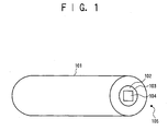
- Fig. 1 is a perspective view of a known CCD camera, and reference numbers 101, 102, 103, and 104 represent a vessel, a front flat glass sheet, an evacuated portion, and a CCD sealed in a vacuum, respectively.
- the vessel 101 having the CCD 104 stored therein is evacuated close to a vacuum.
- the flat glass sheet 102 is provided in front of the CCD 104 so as to tightly seal the vessel 101. Since the inside of the CCD camera is cooled, when the humidity of outside air 105 exceeds a certain limit, dew or droplet of water is formed on the glass sheet 102 even when the humidity of the outside air 105 is not 100%, thereby making the CCD camera useless.
- a variety of methods have been devised and applied. For example, a method of blowing dry nitrogen gas onto a glass surface, a method of blowing heated air onto a glass surface, a method of heating the entire CCD camera, and so forth were devised.
- the vessel tightly sealed so as to be evacuated is deformed, thereby causing not only risking the maintenance of its vacuum state but also consuming more energy for heating the entire camera.
- This is an essential factor to be taken into consideration when the entire camera is heated in the open air by a battery or the like.
- the method of blowing dry nitrogen gas or heated air onto a glass surface causes a disturbance in the air, thereby deforming an image received on the CCD surface due to an air turbulence phenomenon, in addition to having a problem of availability of dry nitrogen.
- an object of the present invention is to provide a method and an apparatus for preventing formation of dew and/or ice on an optical glass window, with which formation of dew and/or ice on an optical glass window is easily and simply prevented while disturbance is minimized and a deformation is inhibited as little as possible.
- an insulated protective tube is attached to the front of an optical glass window, and the air in the protective tube is heated.
- the heated air gently warms the glass window so as to prevent formation of dew and/or ice. Since the air is trapped in the protective tube, the air does not flow and is unlikely to cause turbulent disturbance.
- two cases of application are possible to achieve the aim of the present invention, in which the front surface of the protective tube is closed or opened to the outside air.
- the front surface of the protective tube can be temporarily opened by the shutter when exposure is performed by using a CCD camera.
- the protective tube is formed so as to have a smaller hole (window) for performing exposure to outside light than the protective tube, thereby achieving the aim of containing the air inside the protective tube.
- Fig. 2 is a schematic view of an apparatus for preventing formation of dew and/or ice on an optical glass window, according to a first embodiment of the present invention, wherein Fig. 2(a) is an external perspective view of the apparatus for preventing formation of dew and/or ice on an optical glass window, and Fig. 2(b) is a schematic view of an inclination-angle detector of the apparatus for preventing formation of dew and/or ice on an optical glass window. Also, Fig. 3 is a sectional view of the apparatus for preventing formation of dew and/or ice on an optical glass window.
- 1 represents a CCD camera
- 2 represents a glass window
- 3 represents a CCD enclosed inside the glass window
- 1A represents a flange portion of the CCD camera
- 4 represents a first joint portion
- 5 represents an insulating member
- 6 represents a protective tube
- 6A represents a first flange portion of the protective tube
- 6B represents a second flange portion of the protective tube
- 7 represents a heating tape
- 8 represents an electronic controller having a power supply incorporated therein
- 9 represents a temperature regulator
- 10 represents a second joint portion
- 11 represents an iris
- 12 represents a shutter
- 13 represents a shutter-driving apparatus
- 14 represents an insulating member
- 15 represents a telescopic portion
- 15A represents a flange portion of the telescopic portion 15.
- the insulating member 5 insulating the maim body 1 of the CCD camera or the like and the protective tube 6 from each other may be composed of material such as ceramic, the material is not limited
- the protective tube 6 covering an external atmosphere of the glass window 2 faced by the CCD 3 of the CCD camera 1 and insulated from the glass window 2 is provided. That is, the first flange portion 6A of the protective tube 6 is fastened to tightly seal manner to the flange portion 1A of the CCD camera 1, having the insulating member 5 interposed therebetween, so as to make up the first joint portion 4. Also, the flange portion 15A of the telescopic portion 15 is fastened in a hermetically sealed manner to the second flange portion 6B of the protective tube 6, having the iris 11, the shutter 12, and the insulating member 14 interposed therebetween, so as to make up the second joint portion 10.
- the heating tape 7 serving as a heating device is bonded around the outer surface of the protective tube 6 and is connected to the electronic controller 8 having a power supply incorporated therein. Also, temperature data information of the heating tape 7 is inputted into the temperature regulator 9 so as to regulate a temperature of the heating tape 7.
- an angle 9 made by a horizontal direction 16 and an inclination direction 17 of the protective tube 6 is detected by using, for example, an angle scale 18, that is, detected by an inclination angle detector (alternatively, the electronic controller may have an inclination detector or an inclination-detecting switch disposed therein) 19 detecting an angle of depression or elevation so as to regulate the temperature of the heating tape 7.
- the electronic controller 8 having a power supply incorporated therein supplies power to the CCD camera 1 and, in addition, drives the shutter-driving apparatus 13 so as to open the shutter 12 only when a picture is being taken by the camera.
- the inside of the protective tube 6 is hermetically sealed and is not open to the outside air, whereby dew and/or ice is not formed on the glass window 2.
- the temperature of the heating tape 7 is regulated, warm air is normally filled in the protective tube 6. Accordingly, even when an outside air temperature is low, the glass window 2 is prevented from formation of dew and/or ice.
- the front surface (front portion) of the protective tube is temporarily opened by the shutter when an exposure is performed by using the CCD camera
- the front surface (front portion) can be always opened as described below by applying a design idea on the front surface of the protective tube.
- Fig. 4 is an external perspective view of an apparatus for preventing formation of dew and/or ice on an optical glass window, according to a second embodiment of the present invention
- Fig. 5 is a sectional view of the apparatus for preventing formation of dew and/or ice on an optical glass window.
- 21 represents a camera portion
- 22 represents a lens portion connected to the camera portion
- 22A represents a flange of the lens portion
- 23 represents a glass window of the lens portion
- 24 represents a lens
- 25 represents a joint portion
- 26 represents an insulating member
- 27 represents a protective tube
- 27A represents a flange of the protective tube
- 28 represents a small opening in the front portion of the protective tube 27.
- the lens portion 22 is connected to the camera portion 21, the lens 24 facing the glass window 23 is disposed in the lens portion 22, and the joint portion 25 is made up by fixing the flange 22A of the lens portion 22 to the flange 27A of the protective tube 27, having the insulating member 26 interposed therebetween.
- the small opening 28 is perforated in the front portion (front surface) of the protective tube 27. That is, the small opening (window) 28 for performing exposure to outside air is made smaller than the protective tube 27 so as to prevent air in the protective tube 27 from leaking outside.
- the air in the protective tube 27 is inhibited from leaking outside, thereby effectively preventing formation of dew and/or ice on the glass window 23 of the lens portion 22.
- a temperature regulation can be performed so as to provide a temperature gradient in the protective tube 27, thereby effectively preventing formation of dew and/or ice.
- a lens or a front flat filter for use not only in a research-purpose CCD camera used in a high-humidity environment but also in a general-purpose still camera or a video-TV camera used for taking a picture in an environment such as high-humidity outdoor or night time is prevented from formation of dew and, in an extremely low-temperature environment, is also prevented from formation of ice.
- the heating tape is used as means for heating the protective tube, and the temperature thereof is controlled by a temperature sensor.
- the means for heating the protective tube is not limited to the heating tape.
- a temperature to be set is intended so as to prevent formation of dew and/or ice and varies depending on an environment. This method does not exclude a case where a heating method is different from the above mentioned one.
- the heating tape may be covered by a heat-insulating member in order to effectively control the temperature thereof, the present invention covers both cases of including and excluding the heat-insulating member.
- the size and shape of the heating tape depend on the size and shape of an object such as a camera which is to be prevented from having dew and/or ice formed thereon.
- the present invention provides the following advantages.
- the method and the apparatus are suitable as a method and an apparatus for preventing formation of dew and/or ice on a glass window of a CCD camera, an astronomic telescope, or the like.
Landscapes
- Physics & Mathematics (AREA)
- General Physics & Mathematics (AREA)
- Optics & Photonics (AREA)
- Engineering & Computer Science (AREA)
- Automation & Control Theory (AREA)
- Studio Devices (AREA)
- Lens Barrels (AREA)
- Structure And Mechanism Of Cameras (AREA)
- Cameras Adapted For Combination With Other Photographic Or Optical Apparatuses (AREA)
- Accessories Of Cameras (AREA)
- Camera Bodies And Camera Details Or Accessories (AREA)
Abstract
Description
Claims (10)
- A method for preventing formation of dew and/or ice on an optical glass window, comprising the step of preventing an external atmosphere of the optical glass window from being cooled by providing a protective tube covering the external atmosphere of the cooled optical glass window and insulated from the optical glass window so as to prevent the optical glass window from having dew and/or ice formed thereon.
- The method for preventing formation of dew and/or ice on an optical glass window according to Claim 1, wherein the protective tube is formed so as to be tightly sealed.
- The method for preventing formation of dew and/or ice on an optical glass window according to Claim 1, wherein the protective tube has a small opening perforated in the front thereof.
- The method for preventing formation of dew and/or ice on an optical glass window according to Claim 1, further comprising the step of regulating a temperature of the protective tube.
- An apparatus for preventing formation of dew and/or ice on an optical glass window, comprising a protective tube covering an external atmosphere of the cooled optical glass window and insulated from the optical glass window so as to prevent the external atmosphere of the optical glass window from being cooled and to provide means for preventing formation of dew and/or ice on the optical glass window.
- The apparatus for preventing formation of dew and/or ice on an optical glass window according to Claim 5, further comprising a shutter closing the front of the protective vessel.
- The apparatus for preventing formation of dew and/or ice on an optical glass window according to Claim 5, wherein the protective vessel has a small opening perforated in the front thereof.
- The apparatus for preventing formation of dew and/or ice on an optical glass window according to Claim 5, further comprising means for regulating a temperature of the protective vessel.
- The apparatus for preventing formation of dew and/or ice on an optical glass window according to Claim 8, further comprising a heating tape on the side surface portion of the protective vessel.
- The apparatus for preventing formation of dew and/or ice on an optical glass window according to Claim 8, wherein the temperature of the protective vessel is regulated so as to inhibit convection of air in the protective vessel in accordance with an inclination angle of the protective vessel.
Applications Claiming Priority (3)
| Application Number | Priority Date | Filing Date | Title |
|---|---|---|---|
| JP2001378109A JP3875090B2 (en) | 2001-12-12 | 2001-12-12 | Method and apparatus for preventing condensation and freezing of optical glass window |
| JP2001378109 | 2001-12-12 | ||
| PCT/JP2002/010257 WO2003050585A1 (en) | 2001-12-12 | 2002-10-02 | Method and device for preventing dew condensation and frosting on optical glass window |
Publications (2)
| Publication Number | Publication Date |
|---|---|
| EP1455210A1 true EP1455210A1 (en) | 2004-09-08 |
| EP1455210A4 EP1455210A4 (en) | 2009-12-09 |
Family
ID=19185924
Family Applications (1)
| Application Number | Title | Priority Date | Filing Date |
|---|---|---|---|
| EP02804544A Withdrawn EP1455210A4 (en) | 2001-12-12 | 2002-10-02 | METHOD AND DEVICE FOR PREVENTING THE FORMATION OF ROSED OR FROZEN CONDENSATION ON AN OPTICAL GLASS SLOT |
Country Status (4)
| Country | Link |
|---|---|
| US (1) | US7001028B2 (en) |
| EP (1) | EP1455210A4 (en) |
| JP (1) | JP3875090B2 (en) |
| WO (1) | WO2003050585A1 (en) |
Cited By (1)
| Publication number | Priority date | Publication date | Assignee | Title |
|---|---|---|---|---|
| US10768450B1 (en) | 2019-07-26 | 2020-09-08 | Lineage Logistics, LLC | Mitigation of lens condensation using heat |
Families Citing this family (8)
| Publication number | Priority date | Publication date | Assignee | Title |
|---|---|---|---|---|
| WO2005050508A1 (en) * | 2003-11-18 | 2005-06-02 | Konica Minolta Photo Imaging, Inc. | Face photograph pickup device and face photograph processing system |
| US8194132B2 (en) * | 2006-01-20 | 2012-06-05 | Old World Industries, Llc | System for monitoring an area adjacent a vehicle |
| JP2008233237A (en) * | 2007-03-16 | 2008-10-02 | Sumitomo Electric Ind Ltd | Optical member, imaging apparatus, and lens barrel for vehicle-mounted camera |
| EP2290422A1 (en) * | 2009-09-01 | 2011-03-02 | The Gillette Company | Digital microscope |
| KR20140096913A (en) * | 2013-01-29 | 2014-08-06 | 삼성테크윈 주식회사 | A heater device and a photographing apparatus comprising the same |
| DE102013102816B4 (en) * | 2013-03-19 | 2016-03-24 | Carl Zeiss Industrielle Messtechnik Gmbh | Optical measuring device, in particular autocollimation telescope, with reduced measurement deviation |
| DE102015117780A1 (en) * | 2015-04-30 | 2016-11-03 | Huf Hülsbeck & Fürst Gmbh & Co. Kg | Reversing camera device for a motor vehicle and tailgate system with such a reversing camera device |
| CN112665832B (en) * | 2020-12-30 | 2024-08-02 | 中国科学院西安光学精密机械研究所 | Temperature control device for optical glass window of temperature test chamber and use method |
Family Cites Families (15)
| Publication number | Priority date | Publication date | Assignee | Title |
|---|---|---|---|---|
| US2442913A (en) * | 1944-09-18 | 1948-06-08 | Abrams Talbert | Lens heater |
| US2879424A (en) * | 1955-04-04 | 1959-03-24 | Westinghouse Electric Corp | Image detector |
| JP2653231B2 (en) | 1990-09-25 | 1997-09-17 | 日産自動車株式会社 | Robot for spot welding |
| JPH04135076U (en) * | 1991-06-04 | 1992-12-16 | 株式会社日立製作所 | VTR integrated camera with anti-condensation device |
| JPH0534605A (en) | 1991-07-29 | 1993-02-12 | Olympus Optical Co Ltd | External television camera for endoscope |
| US5343018A (en) * | 1992-10-30 | 1994-08-30 | Wisconsin Alumni Research Foundation | Microscope lens and stage heater with flexible objective lens casing heater sleeve |
| US5470710A (en) * | 1993-10-22 | 1995-11-28 | University Of Utah | Automated hybridization/imaging device for fluorescent multiplex DNA sequencing |
| JPH07236077A (en) | 1994-02-25 | 1995-09-05 | Sony Corp | Camcorder protective case |
| JPH07281291A (en) | 1994-04-07 | 1995-10-27 | Fuji Photo Optical Co Ltd | Thermal insulation cover for TV lens |
| US5714738A (en) * | 1995-07-10 | 1998-02-03 | Watlow Electric Manufacturing Co. | Apparatus and methods of making and using heater apparatus for heating an object having two-dimensional or three-dimensional curvature |
| JP3615846B2 (en) * | 1995-10-04 | 2005-02-02 | ペンタックス株式会社 | Surveying instrument |
| US5904870A (en) * | 1998-05-14 | 1999-05-18 | Midland Manufacturing Corp. | Laser lens heater |
| US6198949B1 (en) * | 1999-03-10 | 2001-03-06 | Optiscan Biomedical Corporation | Solid-state non-invasive infrared absorption spectrometer for the generation and capture of thermal gradient spectra from living tissue |
| WO2001007896A1 (en) * | 1999-07-21 | 2001-02-01 | Tropix, Inc. | Luminescence detection workstation |
| US6825978B2 (en) * | 2002-04-04 | 2004-11-30 | Hypervision, Inc. | High sensitivity thermal radiation detection with an emission microscope with room temperature optics |
-
2001
- 2001-12-12 JP JP2001378109A patent/JP3875090B2/en not_active Expired - Fee Related
-
2002
- 2002-10-02 WO PCT/JP2002/010257 patent/WO2003050585A1/en not_active Ceased
- 2002-10-02 EP EP02804544A patent/EP1455210A4/en not_active Withdrawn
- 2002-10-02 US US10/497,162 patent/US7001028B2/en not_active Expired - Fee Related
Cited By (2)
| Publication number | Priority date | Publication date | Assignee | Title |
|---|---|---|---|---|
| US10768450B1 (en) | 2019-07-26 | 2020-09-08 | Lineage Logistics, LLC | Mitigation of lens condensation using heat |
| US11513370B2 (en) | 2019-07-26 | 2022-11-29 | Lineage Logistics, LLC | Mitigation of lens condensation using heat |
Also Published As
| Publication number | Publication date |
|---|---|
| EP1455210A4 (en) | 2009-12-09 |
| US7001028B2 (en) | 2006-02-21 |
| JP2003177456A (en) | 2003-06-27 |
| WO2003050585A1 (en) | 2003-06-19 |
| JP3875090B2 (en) | 2007-01-31 |
| US20050007665A1 (en) | 2005-01-13 |
Similar Documents
| Publication | Publication Date | Title |
|---|---|---|
| US7001028B2 (en) | Method and device for preventing dew condensation and frosting on optical glass window | |
| US20020140848A1 (en) | Controllable sealed chamber for surveillance camera | |
| US9982895B2 (en) | Baking oven door and baking oven | |
| CN206377923U (en) | A kind of camera device and the refrigerator with it | |
| JP4869427B1 (en) | Condensation prevention mechanism | |
| US20100013984A1 (en) | Noncondensing security camera housing window assembly | |
| JP4143138B2 (en) | Insulated container for liquefied gas | |
| KR20090084383A (en) | Dome Surveillance Camera with Heat Conduction Prevention Heater | |
| KR101343787B1 (en) | Housing for electronic device | |
| CN101443971B (en) | Pressure equalizing equipment housing | |
| CN109963430A (en) | Door body, cabinet, modular data center, anti-condensation control method and device | |
| JP3219750B2 (en) | Storage equipment for video equipment | |
| EP2886001B1 (en) | Insulating article for optical devices | |
| US20080149861A1 (en) | Low-temperature adjustable blackbody apparatus | |
| US20210033274A1 (en) | A lighting device comprising a housing and a bag | |
| RU66576U1 (en) | CASING FOR MONITORING DEVICE | |
| US20080211958A1 (en) | Dehumidified Equipment Housing | |
| JP2010249701A (en) | Heat insulation device for flat panel | |
| JP2000171305A (en) | Infrared detector | |
| JPH07236077A (en) | Camcorder protective case | |
| CN121028447B (en) | A heat dissipation device and method for radiation calibration experiments of space optical cameras | |
| CN117336585A (en) | Camera device and system with thermal insulation and anti-frost function | |
| JP2022076836A (en) | Imaging apparatus | |
| JPH04231532A (en) | Heat-insulating, automatically controlling wall | |
| CN104133504B (en) | A kind of camera shutter attemperator under extremely low temperature and method |
Legal Events
| Date | Code | Title | Description |
|---|---|---|---|
| PUAI | Public reference made under article 153(3) epc to a published international application that has entered the european phase |
Free format text: ORIGINAL CODE: 0009012 |
|
| 17P | Request for examination filed |
Effective date: 20040611 |
|
| AK | Designated contracting states |
Kind code of ref document: A1 Designated state(s): AT BE BG CH CY CZ DE DK EE ES FI FR GB GR IE IT LI LU MC NL PT SE SK TR |
|
| AX | Request for extension of the european patent |
Extension state: AL LT LV MK RO SI |
|
| A4 | Supplementary search report drawn up and despatched |
Effective date: 20091106 |
|
| 17Q | First examination report despatched |
Effective date: 20100916 |
|
| RIC1 | Information provided on ipc code assigned before grant |
Ipc: G02B 27/00 20060101AFI20130225BHEP |
|
| GRAP | Despatch of communication of intention to grant a patent |
Free format text: ORIGINAL CODE: EPIDOSNIGR1 |
|
| INTG | Intention to grant announced |
Effective date: 20130508 |
|
| STAA | Information on the status of an ep patent application or granted ep patent |
Free format text: STATUS: THE APPLICATION IS DEEMED TO BE WITHDRAWN |
|
| 18D | Application deemed to be withdrawn |
Effective date: 20130919 |